Rik Thistle
-
Posts
864 -
Joined
-
Last visited
Content Type
Profiles
Forums
Gallery
Events
Everything posted by Rik Thistle
-
 I’d rather have a well designed kit made from better wood and pay more than save a few dollars. I think that's a very good point. And thinking aloud - I do like Chris' well designed fishing/working vessels for a number of reasons.... - they are more compact than the fighting vessels so take up less room in the shipyard, and the house when finished - they have less repetitive details, and can be finished a bit quicker - they can be bashed somewhat easier (?) since information on them is a little more readily available ie100-150 yrs old rather than 200-300 yrs old. B.E.'s Muirneag Zulu is a great example. - if Chris wished to increase the complexity of his fishing/working vessels and charge more I wouldn't have an issue...eg maybe a Fifie Standard and a Fifie Premium? That's not to say I won't buy another HM Flirt type vessel, but I suspect that my build ratio of small boats: large ships will always be around 2:1 But that's just me...we all have different outlooks so it's only an opinion and a little bit of market feedback for Chris. Richard
 -
You've got her looking quite immaculate. A well balanced looking ship. Richard
- 436 replies
-
- 3
-

-
- vanguard models
- alert
- (and 1 more)
-
glbarlow, VTHokiEE, Thanks for the encouragement and sharing your thoughts on the 'small stuff'. My (current) view on the 'small stuff' is that it is not as much fun as the big stuff, but when finished the Dopamine release is greater 😉 Finishing the 'big stuff' hull is a very visible milestone and you can actually hold the hull in your hand and view it from all angles. But the finer details, well they almost disappear in the noise. But, when finished, it's the finer details that draw the eye in and give just as much, if not more, satisfaction. 2" of snow here today, so feed the birds and then stay indoors working on...the small stuff. Richard
-
Stay safe and wishing you all a better 2021 - same to your and your family. Zulu and Fifie together pic - that's a keeper. I do like the silhouette figures. They give scale and an impression of crew size and activity but don't draw the eye away from the boats and their details. I look forward to whatever arrives next in your shipyard. Thanks again for the Muirneag build story. Regards, Richard
- 261 replies
-
- 5
-
-
- muirneag
- vanguard models
- (and 2 more)
-
Roger, We have gas forced air heat When I was younger the family home had the same. It meant, in winter, the house was full of very dry air which was not good for the sinuses etc. I suspect the forced air heat dries out the air. Richard
-
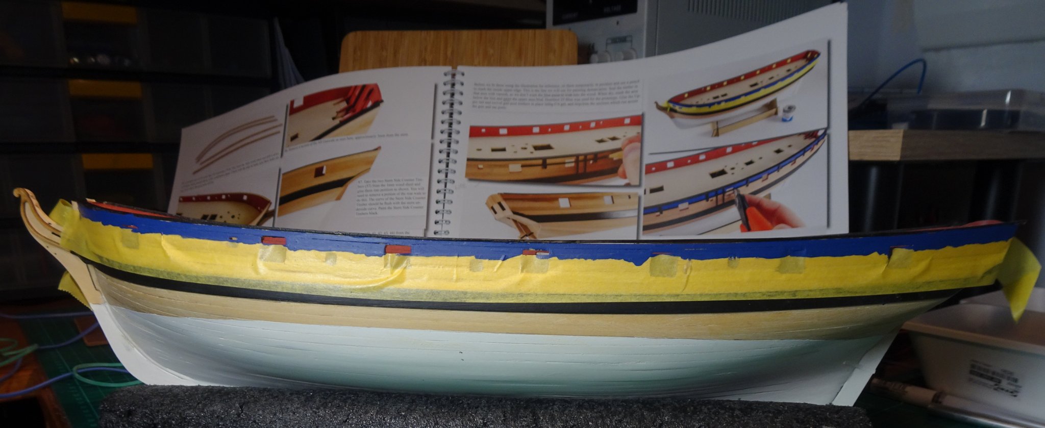
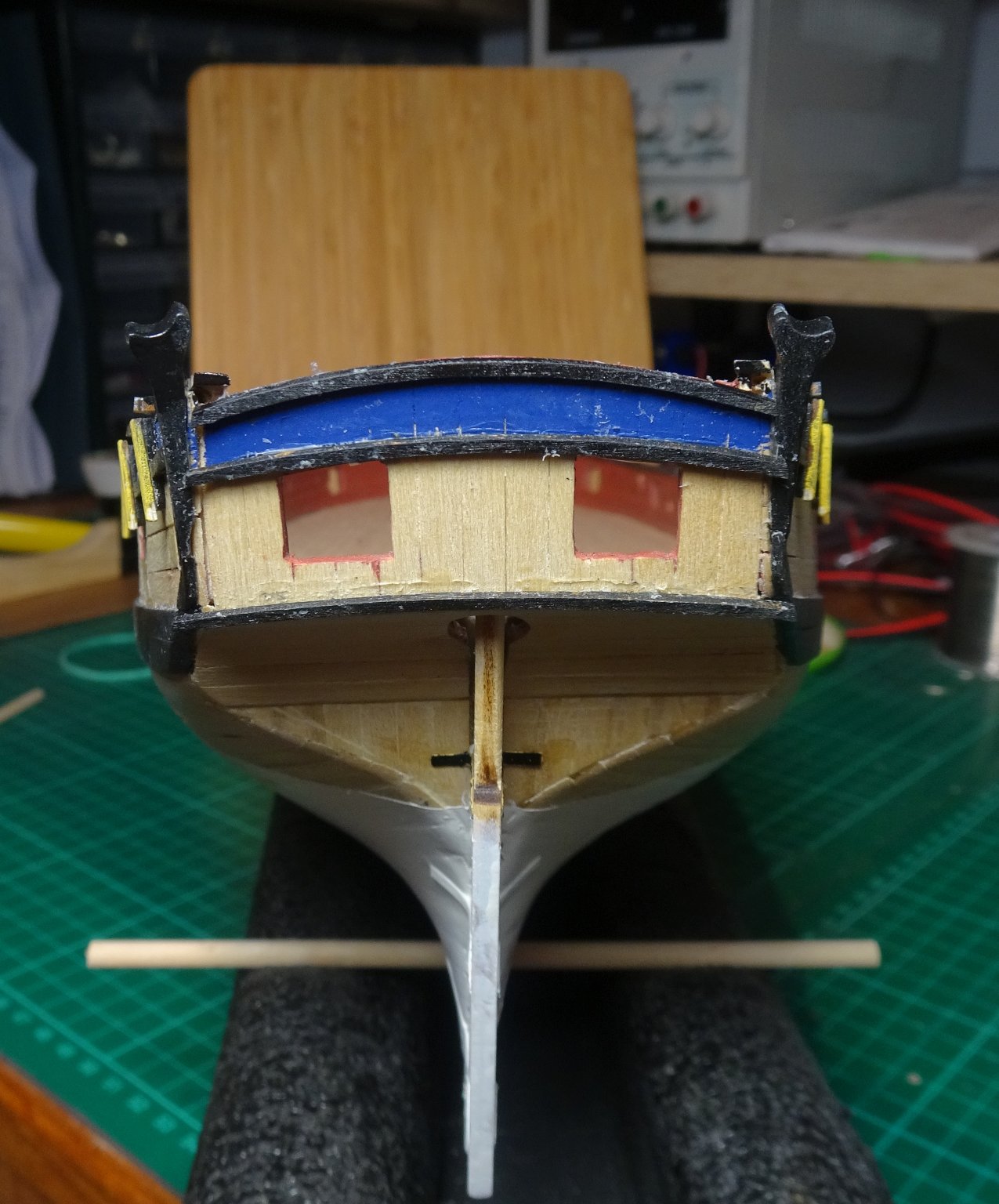
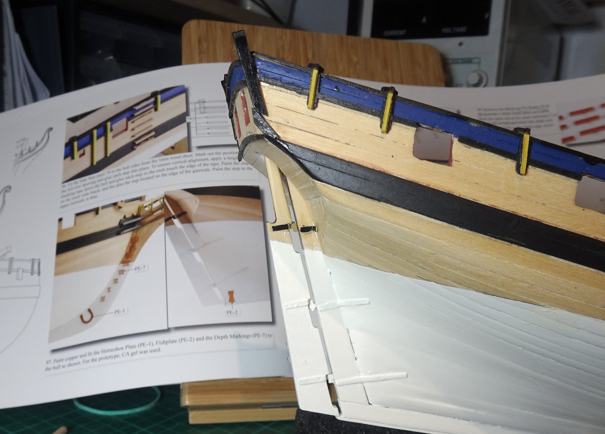
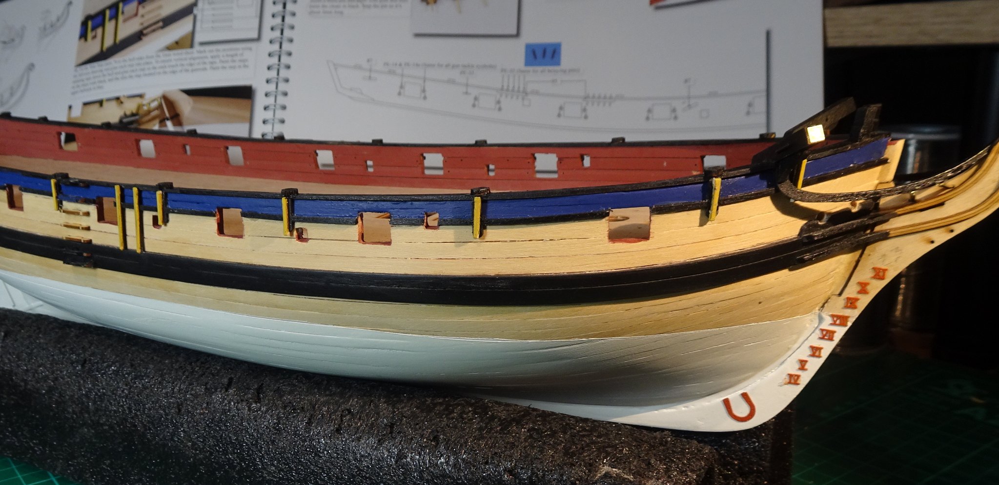
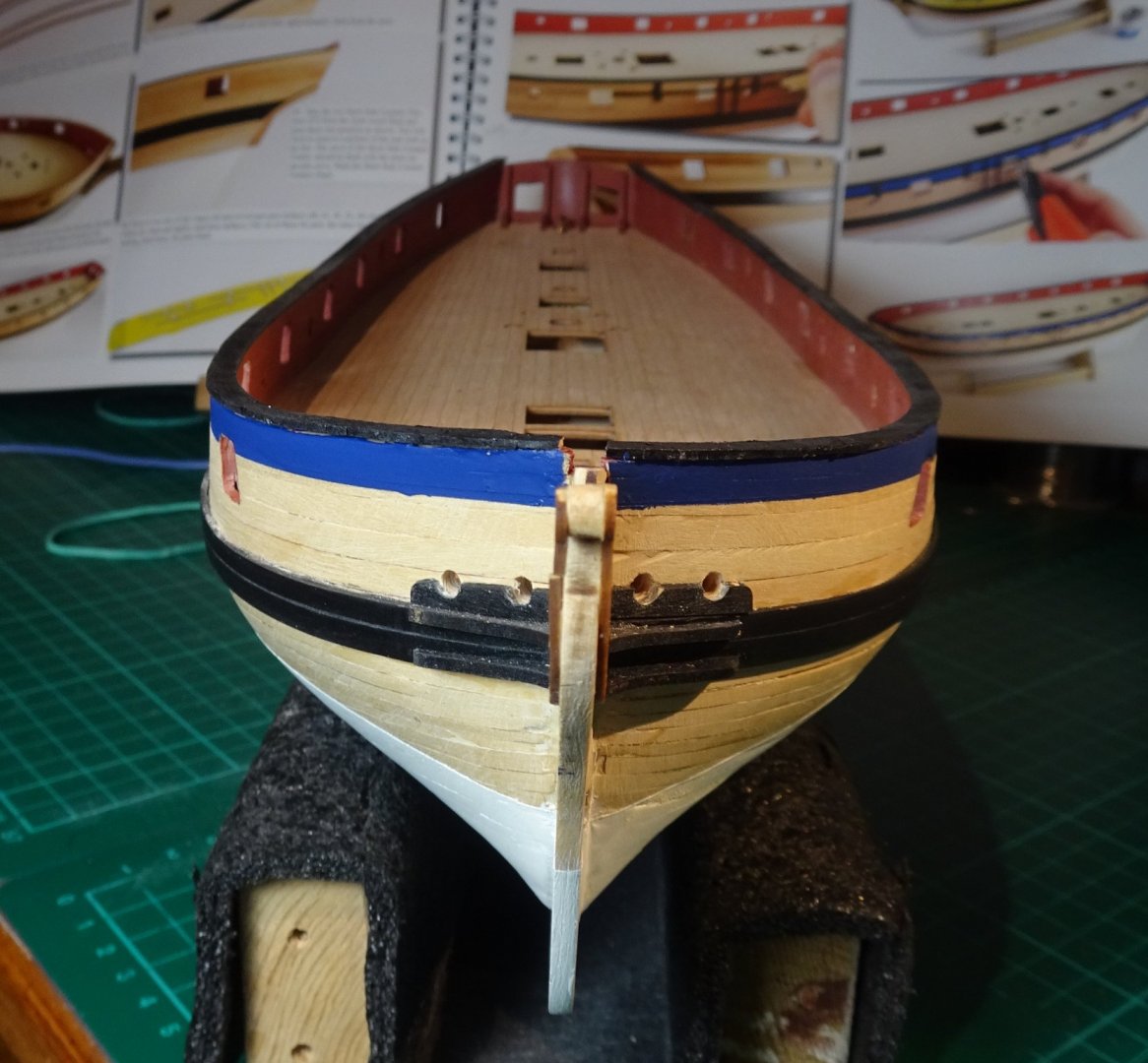
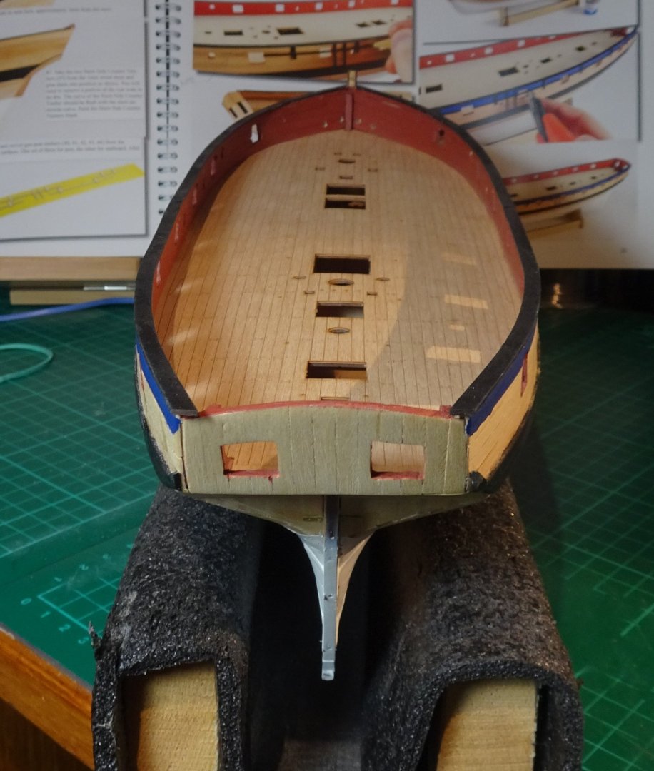
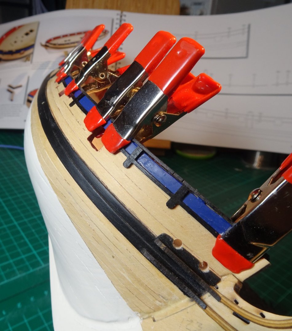
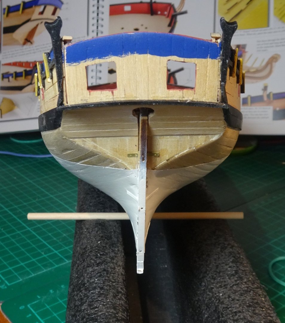
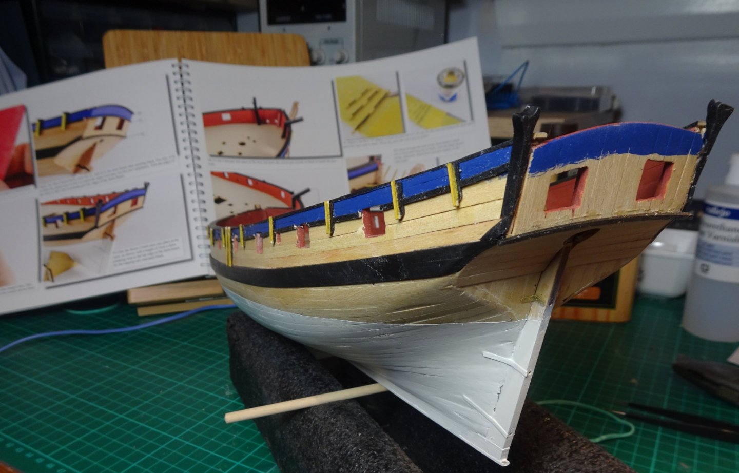
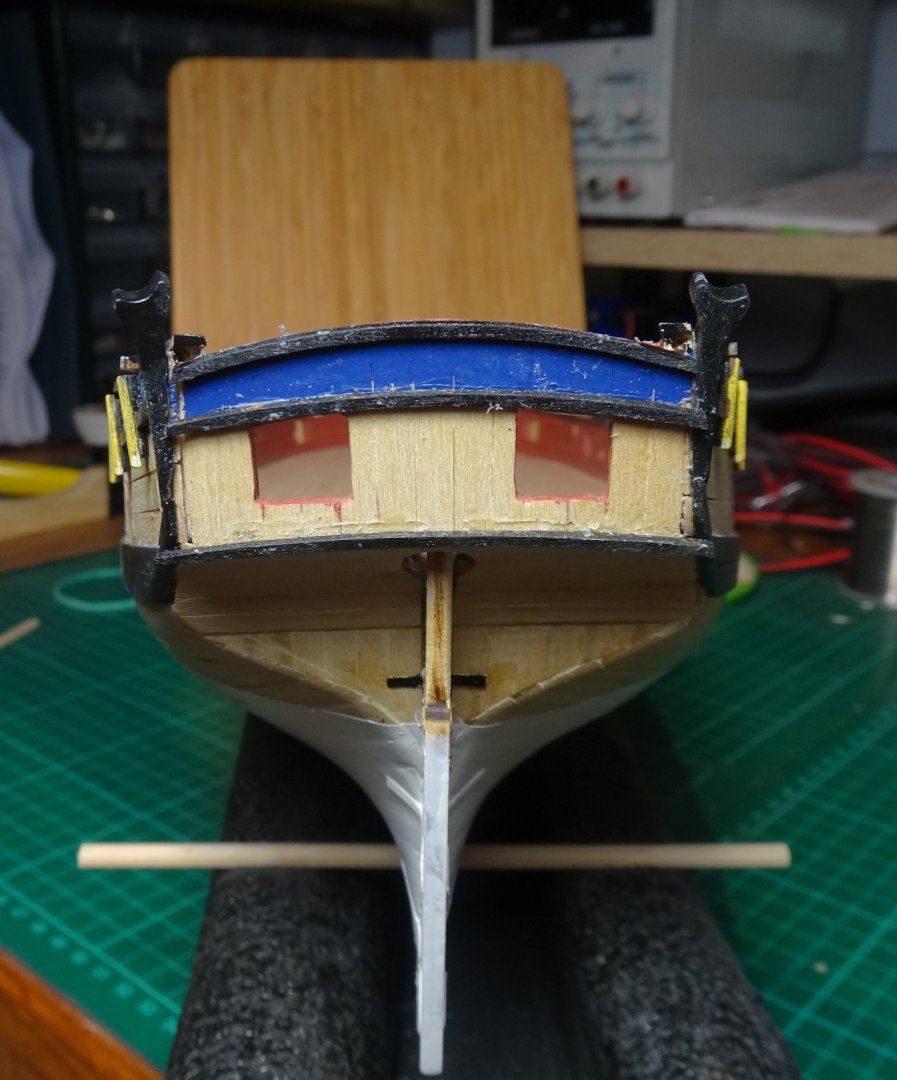
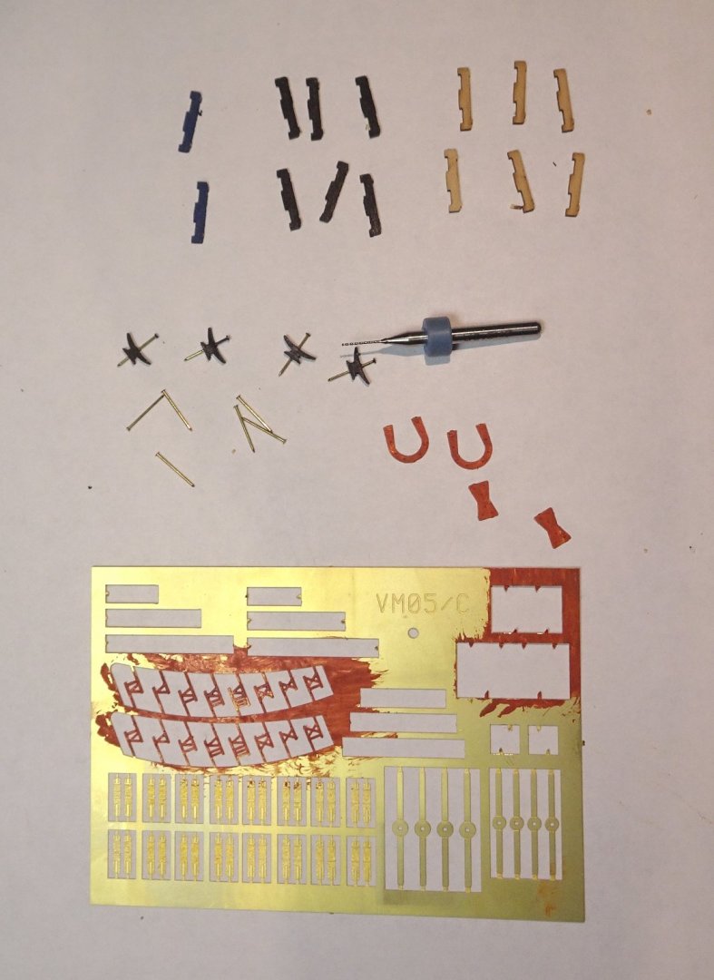
Hi all, Another 10 days or so have gone by, mostly absorbed by small detail work. Although I'm more than half way through the instruction manual that doesn't mean the work is anywhere near half done...nope, the really testing stuff (rigging) is lurking just a few short pages away...gulp. Anyway, the small pots of acrylic paint are now appearing on the workbench. I suspect they will be setting up home there for the next few weeks. Below - The area above the upper rail is painted blue. This becomes an area of high assembly activity so the pristine blue finish is not going to last long! Work also starts on the bow area. Again, the black paint will need re-touching in the days to come. A bare stern 😉 Gun post timbers clamped in position. They kinda went on OK. For some reason I had anticipated, because of their spindleness, they might have been more problematic. Back to the stern, now with a splash of blue and soon to be neatened up under the board rails. Below - Yellow gun support timbers added. It was fiddly getting them centred, some better than others. Black board rails added but the blue paint now has a dusting of ...well, I'd like to say dust, but it's probably excess glue. Nothing another swab of blue paint can't cure though ;-). Below - Now the even more fiddly parts start to make their appearances. A lot of these thin parts require 0.5mm or 0.8mm holes drilled through them. 1) 0.8mm is a bit on the large side and can split the thin part in two if I'm not careful. 2) The 0.5mm drills I have are utter junk and break easily. Today I ordered 10 off better quality ones. (Edit: I later read that someone suggested Jewellers suppliers as a good source of quality drills etc....will investigate) This black, stern side counter timber is a bit of a misfit, so remedial action will happen in due course. However, the rudder now sits happily glued in position. Below - Side steps and depth markings etc fitted. The steps are reasonably parallel (mostly) ...I used a temporary 3mm spacer between them to try to keep them aligned. Well, that's another few days slipped by without any large structure etc being added. But there has been work going on...it's just that it is small stuff, time consuming and not that noticable. And it is Christmas. Regards, Richard


-
That's a good picture. The Zulus really are quite large. And it's good to see your crew are all wearing bunnets....a working man never went out without his bunnet - keeping the head warm was quite important. Well, it looks like Muirneag is soon to leave the shipyard...we'll miss her. But she'll be the best kitted out Zulu setting sail...and the crew will be proud to be on board. Great stuff. Richard PS: Maybe Chris has a Galway Hooker fishing boat on his to-do list? .... https://en.wikipedia.org/wiki/Galway_hooker 😉
- 261 replies
-
- 4
-
-
- muirneag
- vanguard models
- (and 2 more)
-
Drafting
Rik Thistle replied to mangulator63's topic in CAD and 3D Modelling/Drafting Plans with Software
Before CAD, the foolproof way to visualize a project in 3-D was to construct a physical model (aka Space Model). I worked in avionics design. Once we had hardened down on the sizes of the LRU boxes, mounting racks, cable harnesses, cooling ducting etc (LRU = Line Replaceable Unit) we would hand the draught layout drawings to the model making shop. They would make wooden versions with real connectors, and then we would fit the wooden models + harnesses, cooling etc into the actual aircraft. This never failed to reveal certain issues and conflicts with existing structure, access etc. Model shops were a crucial part of the design process. And the people who worked in them were top notch. Richard -
Drafting
Rik Thistle replied to mangulator63's topic in CAD and 3D Modelling/Drafting Plans with Software
The MGB drawing is ink on mylar from 1980. The above is fit for framing and mounting on a wall. A very nice drawing and interesting subject matter. It would work well from A4 to A0 sizes. Richard -
Drafting
Rik Thistle replied to mangulator63's topic in CAD and 3D Modelling/Drafting Plans with Software
Tim, Firstly, yes, thank you for starting the thread...it's brought out a lot of useful knowledge and (somewhat similar) views on drafting/draughting from both sides of the pond and around the world. Secondly, 'Home Economics Class was mandatory for both boys and girls' - in my secondary school it was optional IIRC, and not many lads took it. It probably would have been of great benefit if it had been mandatory for girls AND boys 😉 Richard -
Drafting
Rik Thistle replied to mangulator63's topic in CAD and 3D Modelling/Drafting Plans with Software
Dr PR, Today DesignCAD is considered to be a "hobby" program, and it lacks some of the bells and whistles of more expensive programs. But it is still a very capable 2D and 3D drawing program. Considering it costs about $100 with free bug fixes and technical support, and it has a great free user Forum where you can ask experienced users how to do things and solve problems, it is a tremendous bargain. Thanks. I'll read up on DesignCAD...$100 is well within my 'budget' range 🙂 Richard Later: I see DesignCAD is sold by TurboCAD, who I recognise. Seems it is now $60 ... DesignCAD 2D 2020 https://www.turbocad.com/designcad/designcad-2d.html ...and it's not subscription! I'll watch some YT videos on it. They also have a 3D package DesignCAD 3D Max 2020 and TurboPDF v4 Bundle https://www.turbocad.com/designcad/designcad-3d-max-2020-and-turbopdf-v4-bundle.html at $200 which is kinda within the realms of 'well maybe, one day' budgeting. I'm assuming the two packages would use the same interface design....that is as important as anything. -
Drafting
Rik Thistle replied to mangulator63's topic in CAD and 3D Modelling/Drafting Plans with Software
Hank, Hope this has provided sufficient inspiration and so forth, Yes, and then some 😉 'Maker Clubs' was what I was thinking of when I said 'club'. Yougsters exploring new ideas and gadgets...and good for them. I imagine they will use CAD even if only for 3D printing. But with current movement restrictions I suspect it will be at least summer time before I dare enter a room full of strangers. In amongst the discussions in this thread I was actually looking at Spark. More investigation required. 2D and 3D programs...yes, it might be that getting a freeware version of each it the way forward from a cost perspective but no doubt they will be made by different manufaturers so double the learning curve. I've got all the board drafting tools necessary and was trained to BS308. I still find it very easy to use them to do accurate scale drawings. Unfortunately my drawing board is A2 sized and I am well over 6'...so no sleep overs on there 😉 Good chats on here, as usual...and maybe enhanced even further by the time of year. All the best, Richard -
Roger, “She has been out of the water for several years and is completely dried out.” Yes, I remember them saving the Mary Rose (?) timbers but keeping them constantly sprayed with water, not to save any seals I imagine, but to stop shrinkage nonetheless. I assist with maintenance work on my friend's near 60 yr old wooden framed aircraft and I never fail to be impressed by what an amazing engineering material wood is...as long as it is looked after carefully. Richard
-
Gunther, Basically there is a flexible 'gasket' between each plank to stop water ingress so some swelling or shrinkage shouldn't be a problem because they handle it in the design/construction. Ah, OK, that makes sense. Thanks. Richard
-
Drafting
Rik Thistle replied to mangulator63's topic in CAD and 3D Modelling/Drafting Plans with Software
Terry, Currently using Coreldraw X7 for drafting ship plans. If I ever get in to scratch builds (and I would like to, eventually) then maybe...but at the moment £700 = two good ship kits ... however one day I'll maybe have to bite the CAD bullet. There were also some comments earlier on about investing in CAD training...so perhaps I should consider joining a CAD club or do night school to get a feel for CAD first. Anyway, thank you for the comments. Richard -
Drafting
Rik Thistle replied to mangulator63's topic in CAD and 3D Modelling/Drafting Plans with Software
I miss seeing the draughtman's dance: doing a few lines, standing back to review the work, stepping forward to fix or add to it. 😉 I did that dance for a few years. Then we moved to a more compact room and were supplied with draughtsman's chairs...but you can't work an A0 sized drawing from a seating position so we always ended up standing at the drawing board and then turning round and sitting at the design desk. And of course, I was younger then and standing for hours was not a chore. 3 or 4 companies and a number of job changes later, I retired early, and just at the time they were clearing out the 'old' drawing office...so a number of draughtsman's chairs were up for grabs...and I got one. It's been in my shed for years and I wouldn't swap it for any other chair...it's a masterpiece of functional design...robust, comfortable, stable, height adjustable, a ring to put the feet on etc...wonderful. Richard -
Drafting
Rik Thistle replied to mangulator63's topic in CAD and 3D Modelling/Drafting Plans with Software
Rick, Thanks for the feedback. The closest thing I can think of to a "one size fits all" package would be Solidworks. I have tried many of the "usual suspects"; Delftship, Autocad, Revit, Solid Edge (for more than a year), Rhino, and Catia. On cost/benefit basis, I have found Solidworks beats them all, hands down. Being retired, I can't justify the cost of Solidworks (£7k-£10k ?) but it does look very competent. And, as you mentioned, it takes a fair commitment in 'time' to get up to speed on such software. I'll maybe have to lower my sights and just keep my eyes open. I have tried SketchUp and FreeCAD but none seemed to match my main need for 2D draughting. 3D is a 'nice to have' but not essential at this time. Richard -
Seasons greetings. Health. Wealth. Happiness And to you and your's all also. Although I was aware of the Arctic Convoys I never really knew about them. So I have just spent a bit of time on Wikipedia reading up on them.... strategically very important events and very brave people involved. I found out there were a number of books written and a film made. I will try to find out where this film is available.... https://www.prlib.ru/en/news/684563 Richard Edit: I found this film ... https://www.amazon.co.uk/PQ-17-Arctic-Convoy-Disaster/dp/B00JAI29AM ...it's Clarkson commentating but I think he knows when to be serious.
-
Bob, That's six inches of grain to shrink tangentially and even at a rate of movement of one percent, you are getting close to a sixteenth of an inch, which would be a quite noticeable crack in a model's topsides. Yes, that does make me stop and think. Useful info, thanks. As a non-sailor but ex-engineer how do full sized wooden boats and ships cope with that movement....pumps? Richard
-
Drafting
Rik Thistle replied to mangulator63's topic in CAD and 3D Modelling/Drafting Plans with Software
I was trained in traditional draughting at school and later to the BS 308 draughting standard (now superseded by BS 8888). It used 0.7mm lines for object features and 0.3mm lines for dimension leader lines etc...those different line thicknesses made it easy to 'read' engineering drawings. I keep promising myself I will learn 2D/3D CAD but my heart just isn't in it. I have a desk mounting, Rotring A2 draughting board and all the instruments necessary to quickly and accurately sketch up scale drawings of most things I need to draw. I think one of the main reasons CAD draughting is dominant is that it forms a cost effective part of the digital manufacturing chain, the same chain that is replacing expensive humans at each stage. Other small, but not insignificant benefits of CAD draughting is that A0 drawing storage and A0 printing is no longer required. And 'copies' of drawings can be sent in a second rather than days. I have tried CAD packages but the learning curve seems too steep. If anyone can recommend a cheap, one-size-fits-all package that is easy to learn and suitable for mechanical engineering, ship plans and 3D printing I would be grateful 🙂 Richard -
I hope you find many, many more items to add to keep the build going for another year or two 🙂 Great work, Richard
- 261 replies
-
- 4
-
-
- muirneag
- vanguard models
- (and 2 more)
-
I've got the blue Lowes in my shed for small work, and the yellow Stanley in my study. The Stanley is the one to go for because of it's flexibility and reasonable build quality. The ball joint on mine (bought 7 yrs ago) was tight and rough so I took some Emery cloth to the ball and that fixed it. The Stanley comes with plastic soft jaws and the metal jaws have a groove running the length of the jaw and also a groove at right angles to the first in the centre of the jaw...both grooves are very useful for gripping cylindrical objects. It clamps quickly onto a desk surface (....the Stanley clamping surfaces are plastic covered to protect the desk). For £20 the Stanley is good value ... https://www.amazon.co.uk/gp/product/B001HBS0I0/ref=ppx_yo_dt_b_search_asin_title?ie=UTF8&psc=1 Richard
-
Yes, it is. Just taken from a different angle but mounted in a newer (?) base. The different angle may give another take on the routing of the ropes, but it's not a high res pic. Richard
-
Another pic here .... from https://www.authenticireland.com/blog/aberdeen-aberdeen-prettiest-town/ ...scroll down almost half way. Now set in a larger base. Richard
-
Erik, Congrats on the successful team presentation, and getting back to the shipyard for the festive period. BF 1479 is looking very neat and (in my imagination) keen to get a catch on board ;-) Richard
- 222 replies
-
- 3
-
-
- First Build
- Lady Isabella
- (and 2 more)