
Rik Thistle
-
Posts
808 -
Joined
-
Last visited
Content Type
Profiles
Forums
Gallery
Events
Posts posted by Rik Thistle
-
-
-
Use 'FINISHED' in the title (all caps), but 'done' as a tag.
Argh...I've just 'done' all my non-ship builds. I'll go back and change them to Finished. Sorry for misunderstanding.
Richard
- Old Collingwood, Canute and mtaylor
-
 3
3
-
Chris,
Ah, I didn't realise that tags were not used on non-ship builds - my apologies. Thanks for doing that.
Richard
PS: I see that I should also use 'Done' rather than 'Finished' on non-ship builds. I'll modify those headings now.
- Egilman, Canute, Old Collingwood and 1 other
-
4
-
Hi all,
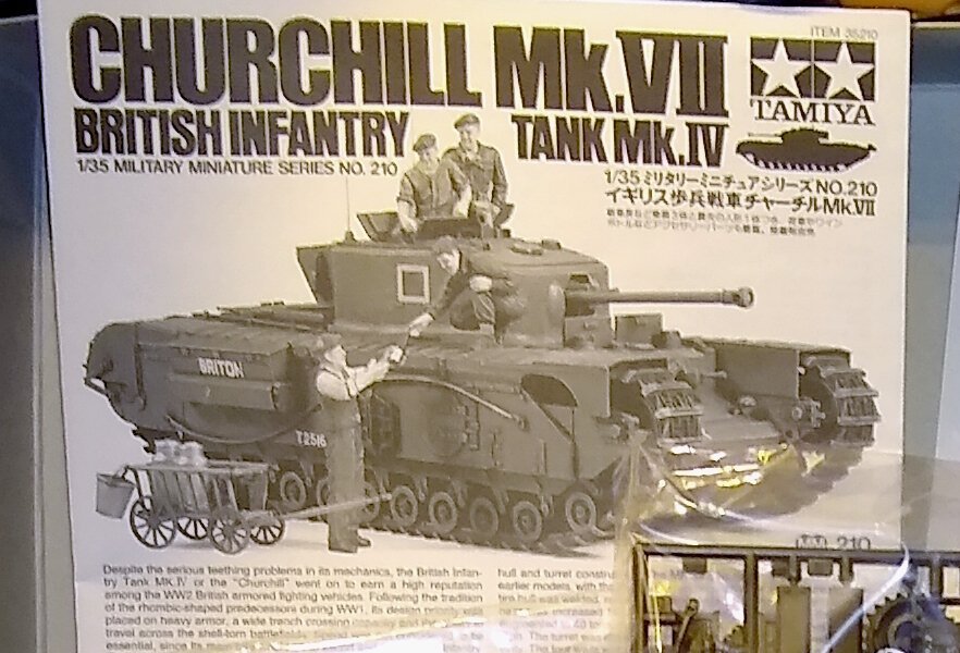
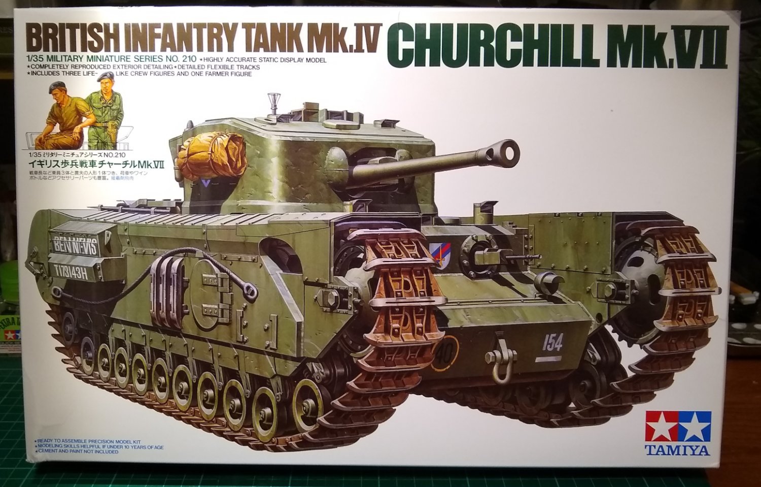
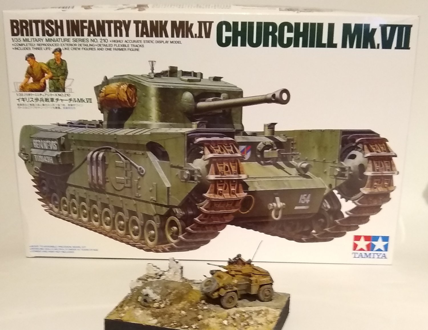
Continuing my venture into the plastic modelling world I have upped the scale to 1:35, and gone for Tamiya's MkVII Churchill tank.

From the Tamiya website ....https://www.tamiya.com/english/products/35210churchill7/index.htm
"This is a 1/35 scale plastic assembly kit model of the British Infantry Tank Mk.IV Churchill Mk.VIII. Introduced at the end of 1943, the tank demonstrated its worth during the Normandy invasion while supporting Allied infantry units. The traditional form of the tank, including the unique suspension system with multiple small road wheels, has been faithfully reproduced. In addition, the kit comes with figures which depict a commander, gunner, driver, and a farmer. Abundant accessories such as a cart and milk cans are also included to create a simple diorama."
From Wiki, the production years/numbers were...
Churchill I 1941 303
Churchill II 1941–42 1,127
Churchill III late 1942 675 or 692[30]
Churchill IV 1943 (together with Churchill V) 1,622
Churchill V 1943 (together with Churchill IV) 241
Churchill VI early 1944 (improved Churchill IV) 200
Churchill VII 1944 (together with Churchill VIII) 1,400
Churchill VIII 1944 (together with Churchill VII) 200The Churchill was seen as a bit of a rush-job at first, with more armour added as the war progressed at the expense of speed. It seems many of the MkVIIs were used as flame throwers.
I will do my best to 'weather' the Churchill kit once built, and probably also build it in to a Normandy setting.
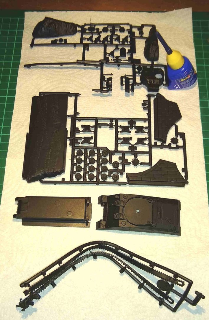
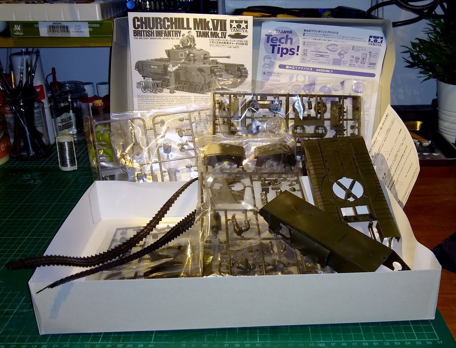
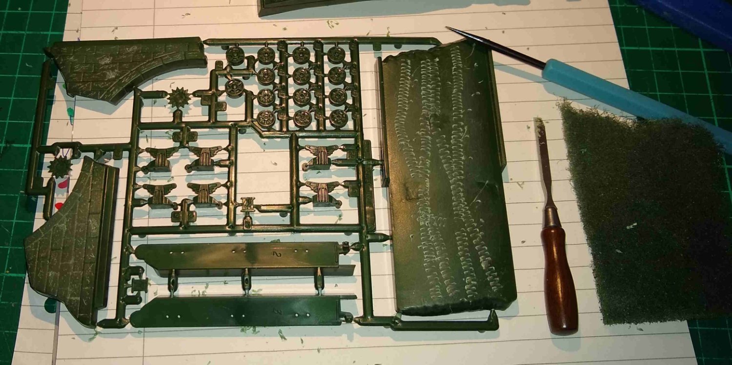
Below, the box contents. It is not the most complex of kits but is still a nice challenge for me.

The kit also comes with Four figures and a milk cart. One does need one's milk for one's mid-afternoon tea. (Edit: On closer examination it is not milk...more likely Red wine ...that's our boys!)
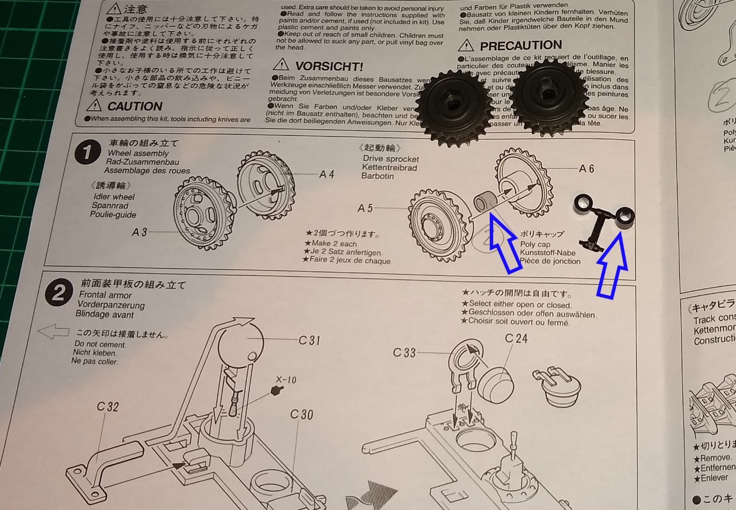
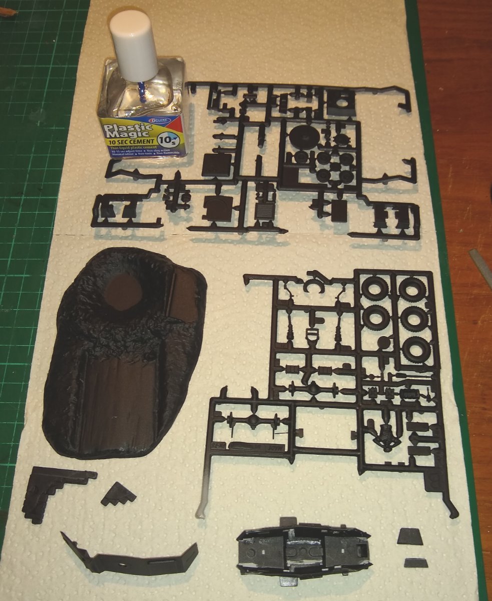
So, straight in to the build, and immediately puzzled. It seemed there should be 4x 'Poly Caps' included that I could not find. After 3 days of searching the kit's plastic bags I did eventually locate them in one of the bags. It's strange how you can look in the same place a number of times for something only to find it on the 3rd or 4th look. The 4x black Poly Caps were all attached to a small sprue. I believe the Poly Caps provide a friction fit for sub-assemblies allowing easy removal for painting etc.

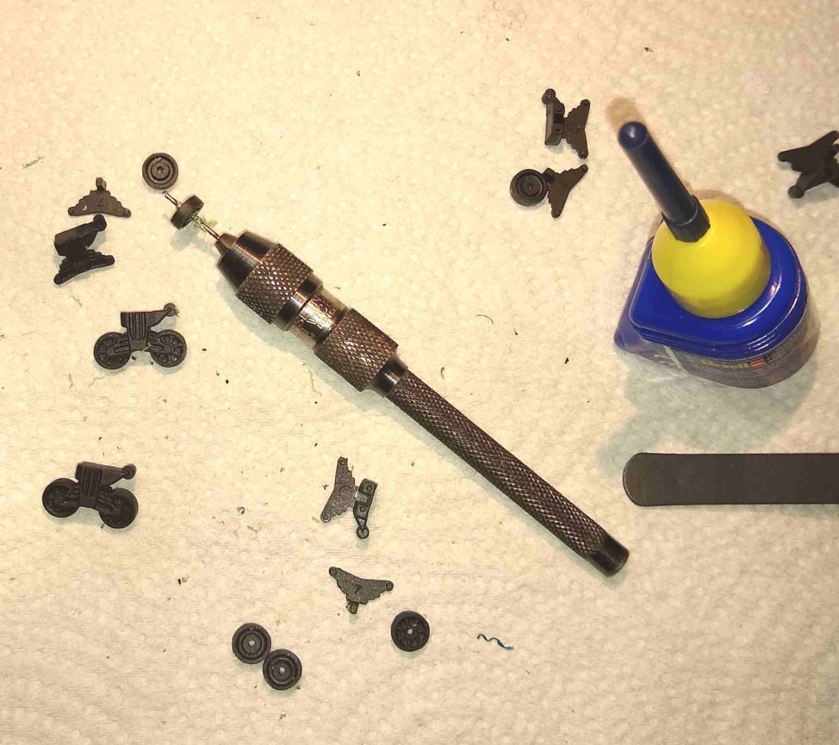
Two of the Poly Caps went in to a pair of Drive Sprockets (above), the other two went in to a pair of upright housings (below).
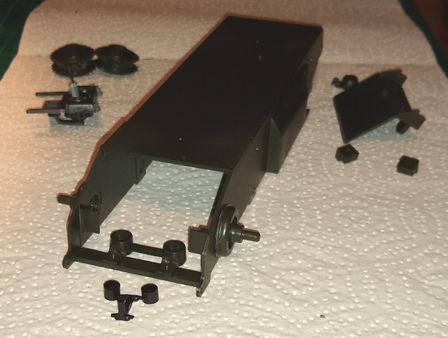
Now on to fitting the Road Wheels. Once the wheel halves were glued together all, bar one, rotated freely. I guess some of the cement must have wicked in further than intended on that one. I'm still learning what the optimum amount of glue is required is.
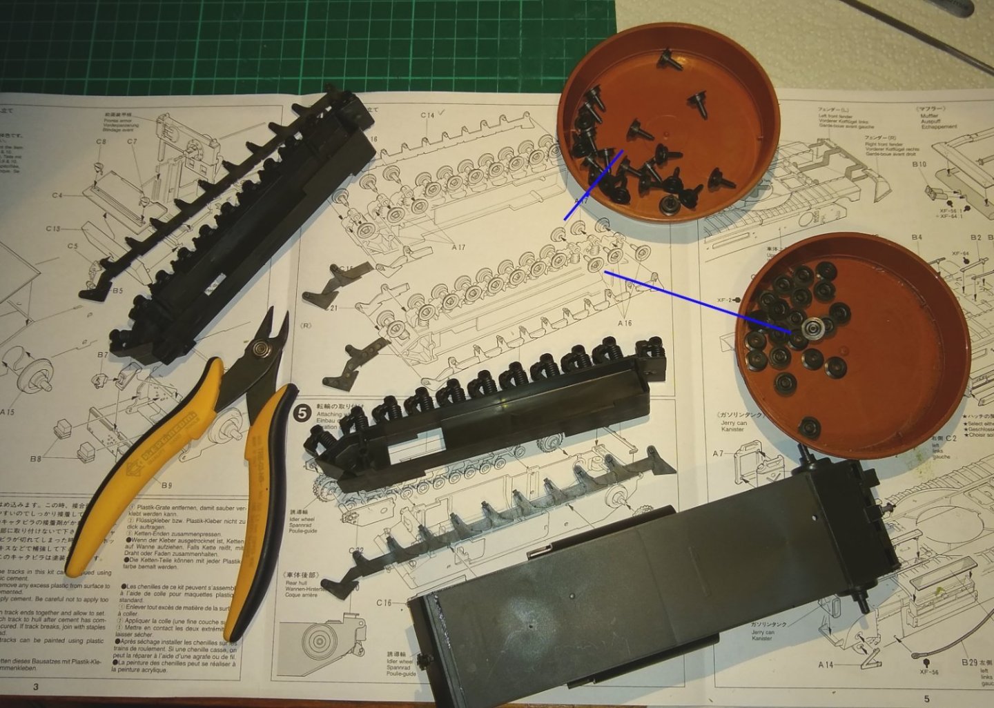
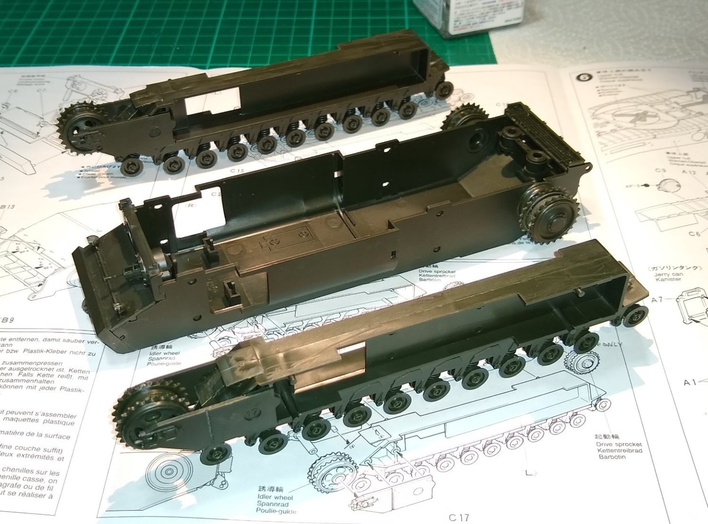
The Hull parts laid out waiting for the Idler Wheels and Drive Sprockets to be fitted..

The Hull sub-assemblies. I won't fit them together until I get a feel for what painting will be required. Note: There is actually a battery compartment in the Hull as the model was initially intended to have a simple Radio Control functionality - I don't think that was ever made available though?
This was just a short post to get the show on the road. Next post should cover the Upper Hull and maybe some of the Turret assembly.
All for now,
Richard
- Haliburton, mtaylor, Ryland Craze and 7 others
-
10
-
OC,
Thanks for that.
I've got the model now sitting on a shelf to my right in the Study. I'm happy with it, but I feel it is missing an extra feature like a dried tree or shrub...or something (?) to give a bit more height to the overall scene. If inspiration arrives I'll post a pic of the mod.
In the meantime I have a Churchill tank entering the production line 🙂
Richard
-
Hi Jaager,
That was a good weight comparison you did....it surprised me too that it was almost 7x.
So you are dealing with a significant increase in kinetic energy. That, plus adding a new motor would tend to push me towards trying to find an existing, off-the-shelf solution that has been design tested by the manufacturers and then many users.
I know you are tight for space, but I would avoid tempting Fate at all costs 😉
Richard
-
Jagger,
A 4" dia piece of Aluminium rotating at a possibly higher rpm will contain a lot more energy than the previous (lighter) wooden block. You'd really need to make sure any bearings, support structures, cooling etc were up to the task. I'd tread carefully....not saying it wouldn't work but be wary.
Richard
-
Ken,
Thanks for all that.
There are other plastics out there, such as ABS....
I'll double check what the plastic pieces I did the tests on are made of...they were offcuts from the Humber model sprue....apparently the plastic type should be stamped on it somewhere.
Richard
- mtaylor, Egilman, Old Collingwood and 2 others
-
5
-
Hi all,
A short finale to the Humber build.
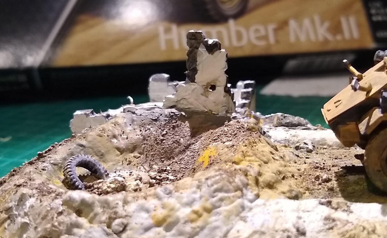
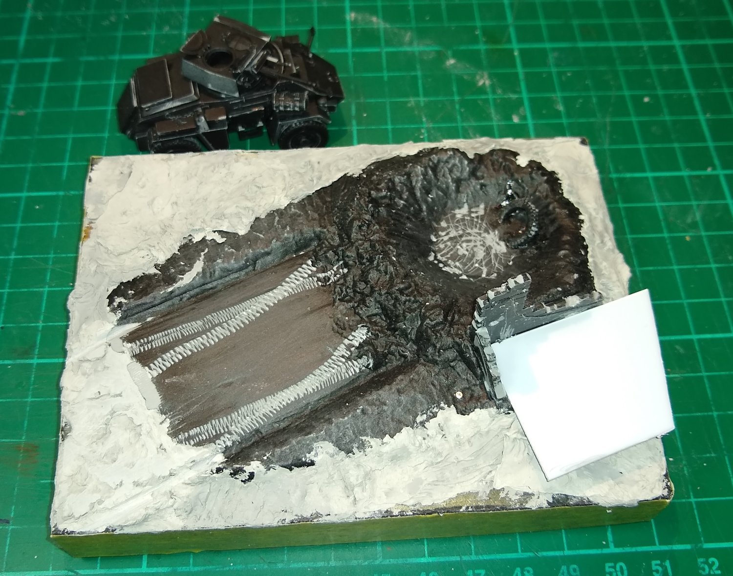
I added a bit more structure to the damaged building. Dried and micro-waved garden earth and small stones were liberally sprinkled over quite a number of areas, and held in place by watered-down PVA glue.

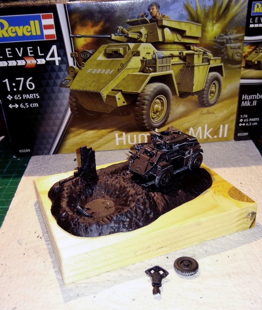
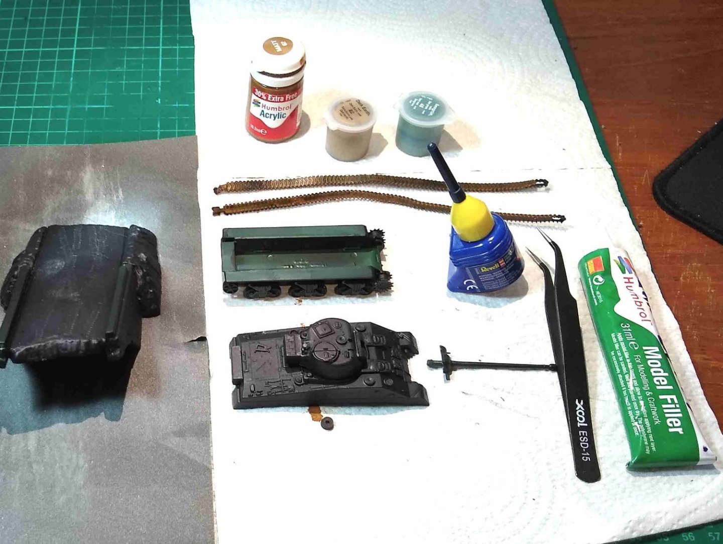
Positioning the Humber in the setting to get a feel for composition.

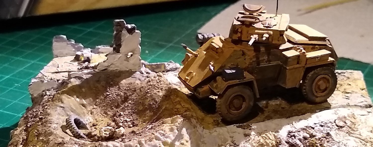
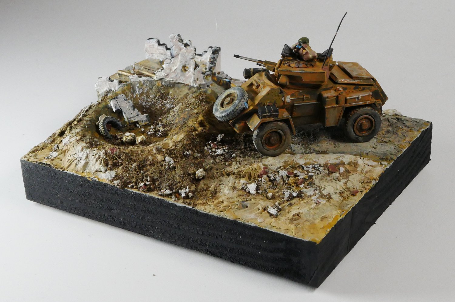
And the final scene. Part of the building has collapsed in to the crater, along with some other debris. Plenty skree all around. I added an antenna to the vehicle...I used 0.35mm wire (...the smallest wire I could put my hands on) , but probably half that diameter would have been more in keeping with the scale. I've deliberately driven the scout car up onto the bank to give the Commander a slightly higher viewpoint.

Edit: Transfers added. Only 4x small ones ie 2 white registration numbers at front and rear, and two ident numbers on mudguards.
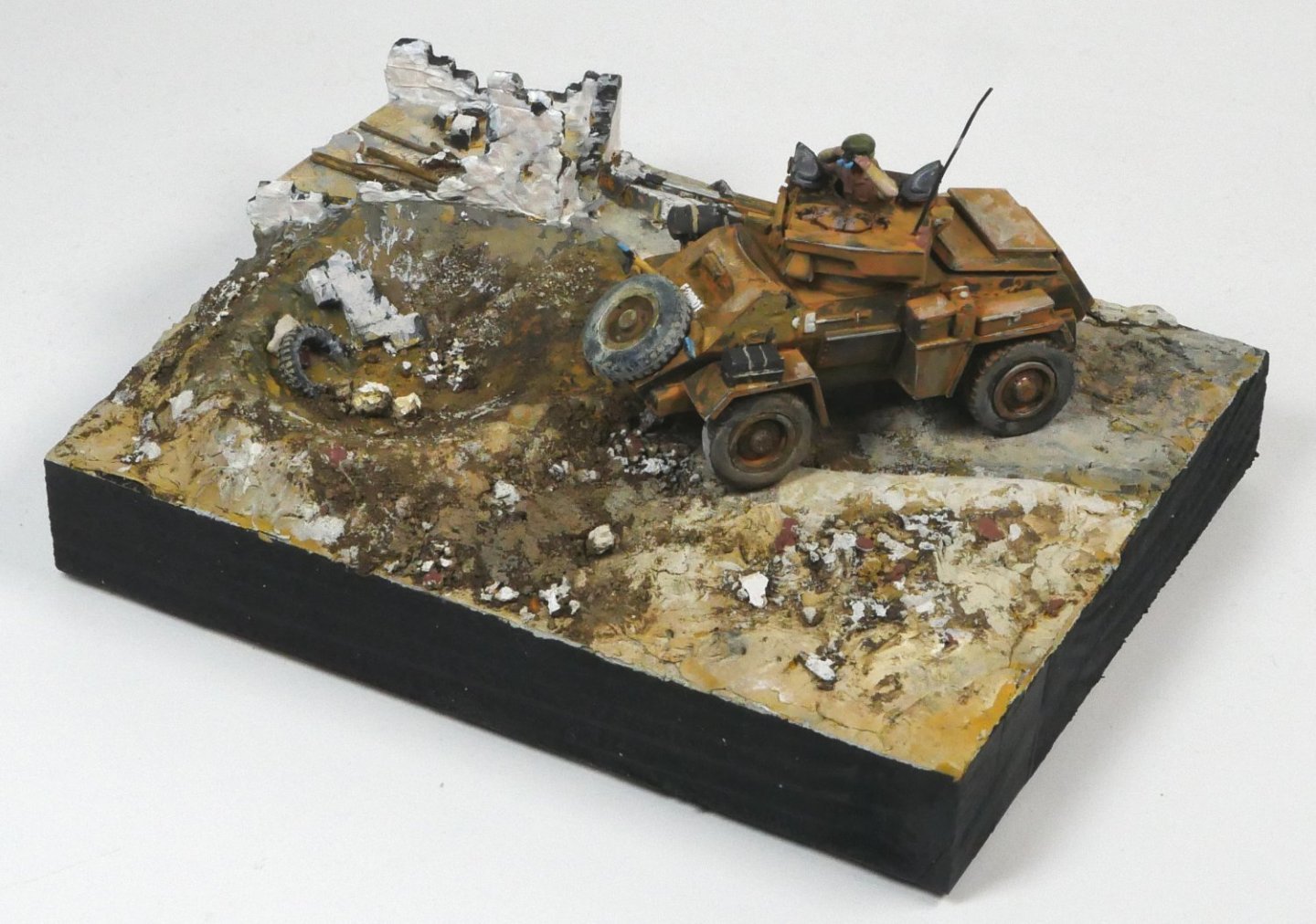
Edit: Repainted the ruined building brown, and added some vegetation.
My 'weathering' has a long way to go, but from a distance I don't think it is too bad. It was an enjoyable little build, which filled in an hour or so each day....I could see myself doing another similar build. As with all builds I learned a good bit more about the vehicle than I had previously known, which is a big part of the enjoyment.
As for 'glues', I only used CA and PVA. The Tamiya Extra Thin cement only arrived today and it certainly has a strong smell. The other glue I bought about 10 days ago is Plastic Magic 10 Second cement, which doesn't smell as bad. I believe both melt the plastic to form joints. I did a quick couple of test joints on some scrap plastic with both but neither held - more tests required. (Edit: The Plastic Magic glue seems to work fine on the Churchill tank, although it has about 3x the cure time of CA).
Thanks for all the Comments and Likes.
Regards,
Richard
PS: As I was finishing the Humber I heard a loud rumbling at my door...this was sitting outside.... gulp!

-
Egilman,
Thanks for all that.
Yup, the Govt mandate for headaches works... for the past fortnight I've had mild headaches - I generally don't suffer from headaches, so I'm putting it down to the new 'substances' I've been playing with.
I've used CA glue extensively in the past without too much issue, but the Revell glue fumes were bad, as was the Humbrol putty's. The problem with the Revell glue container was that re-fitting it's long nozzle cap was a two handed job whereas a cap brush, as you mention, is quickly replaced with only one hand back onto the bottle. I'll let you know how I get on.
My drinking days are long behind me so there will be no temptation to guzzle the stuff 😉
Richard
- mtaylor, Egilman, king derelict and 3 others
-
6
-
Derek,
Thanks for the feedback.
I use Tamiya Extra thin and find that it smells.
Darn 😞 I use a small USB fan and an open window, but the solvents in some of those glues and putties are very strong smelling. Having said that the AK Putty seems odourless. Anyway, all part of the fun learning process 🙂
Richard
- Canute, Old Collingwood and mtaylor
-
3
-
Hi all,
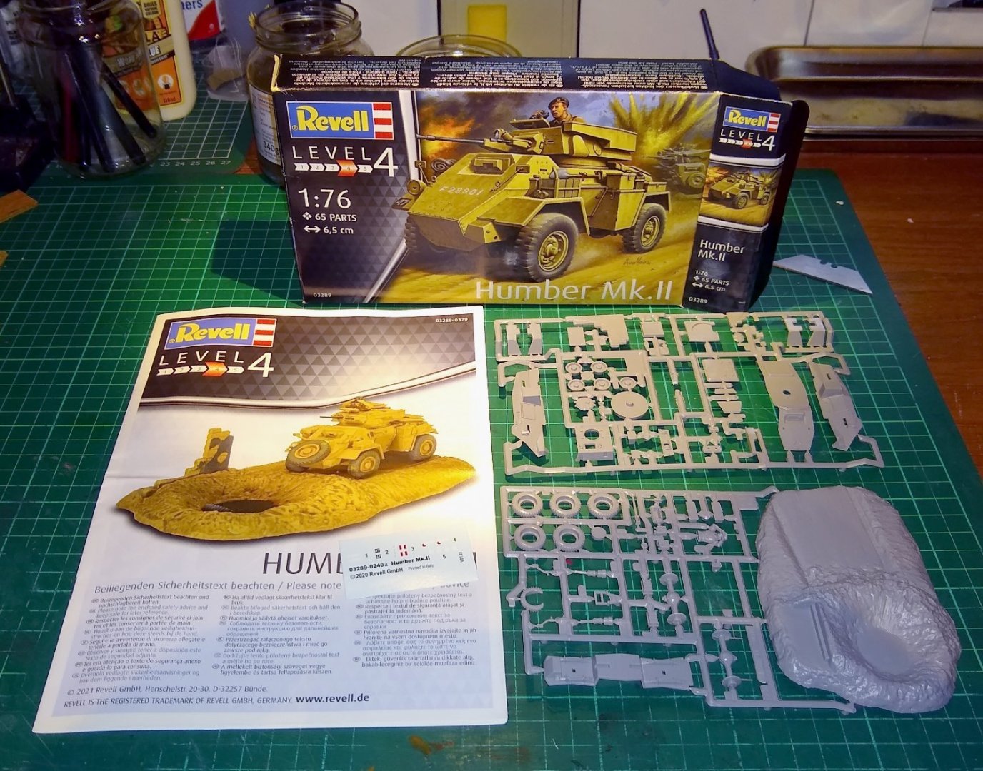
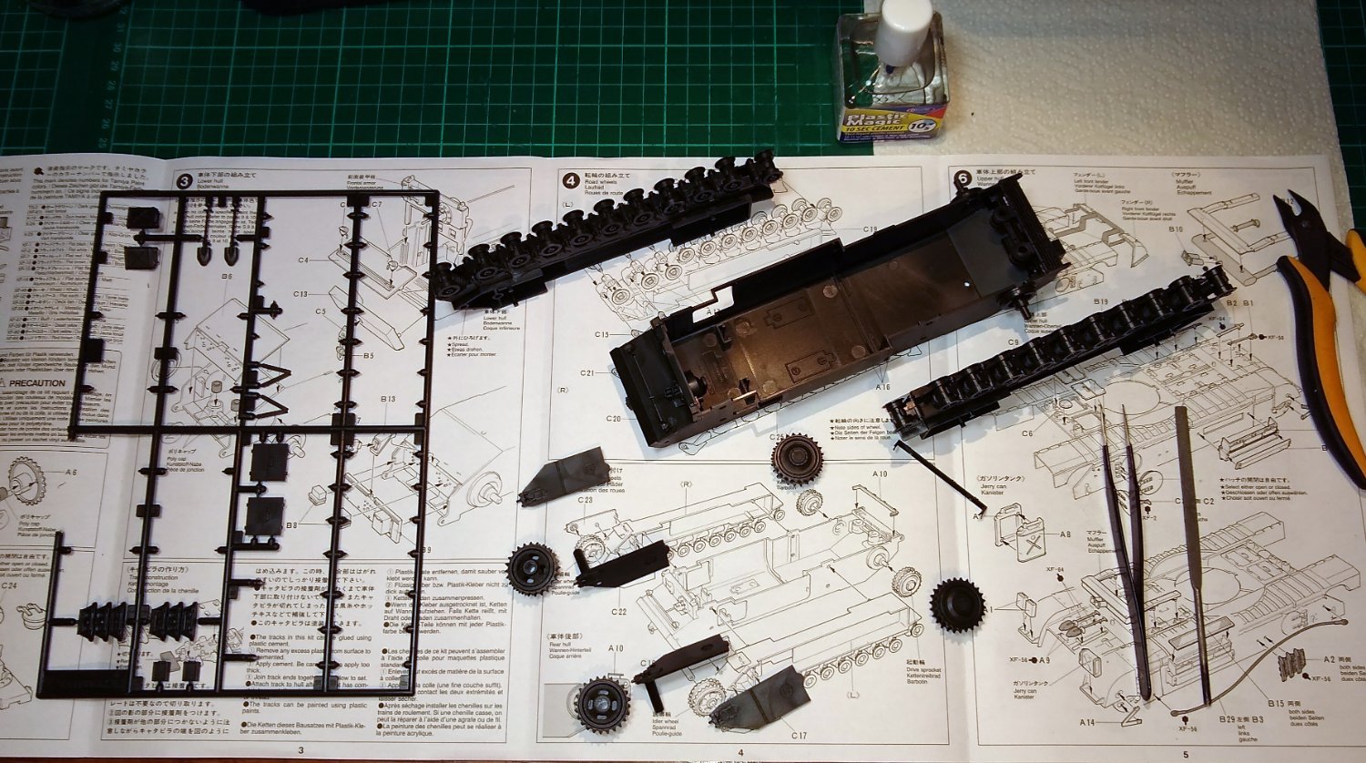
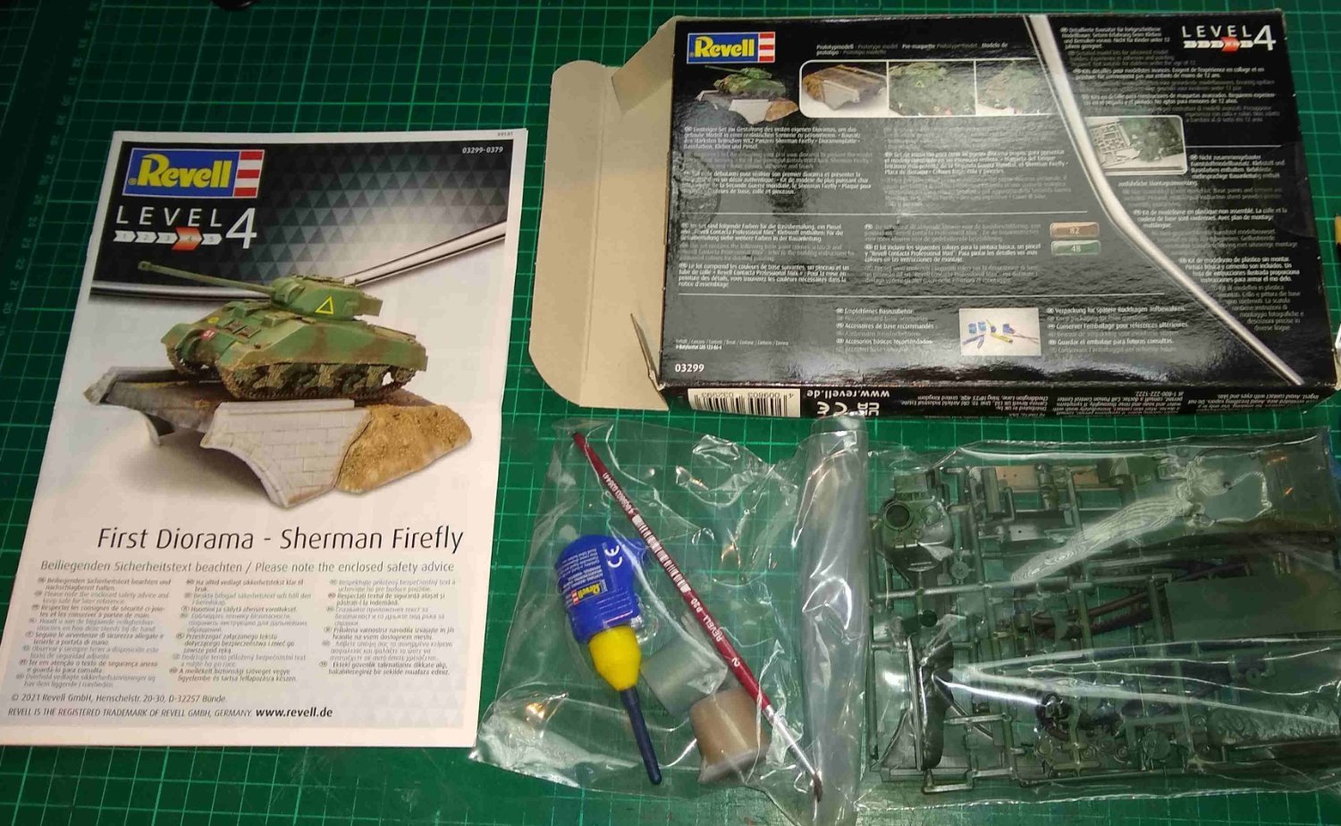
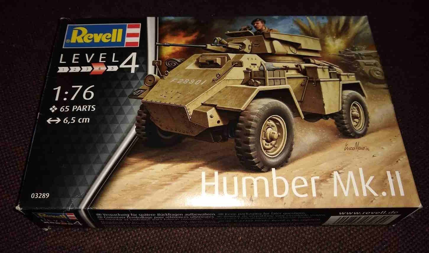
Continuing my Beginner's journey in to the world of plastic modelling, I bought the kit below, a British Army Humber MkII Scout Car. It comes with a Commander and a small diorama base. It was less than £10...no paints, glue or brush were included in this edition. I visualise it being used in North Africa.
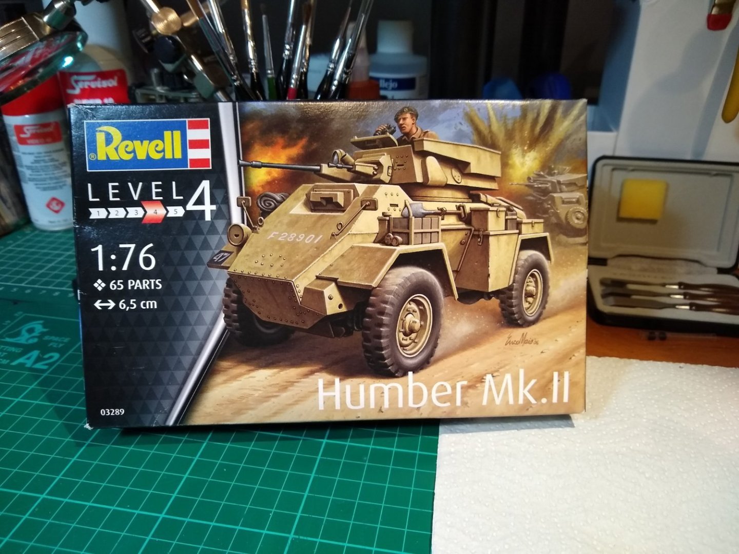
A quick look at the box contents - the manual, transfers and the plastic bits. There are 65 parts in the kit - 'Level 4' on the box refers to the approximate number of parts, rather than the skill level required.
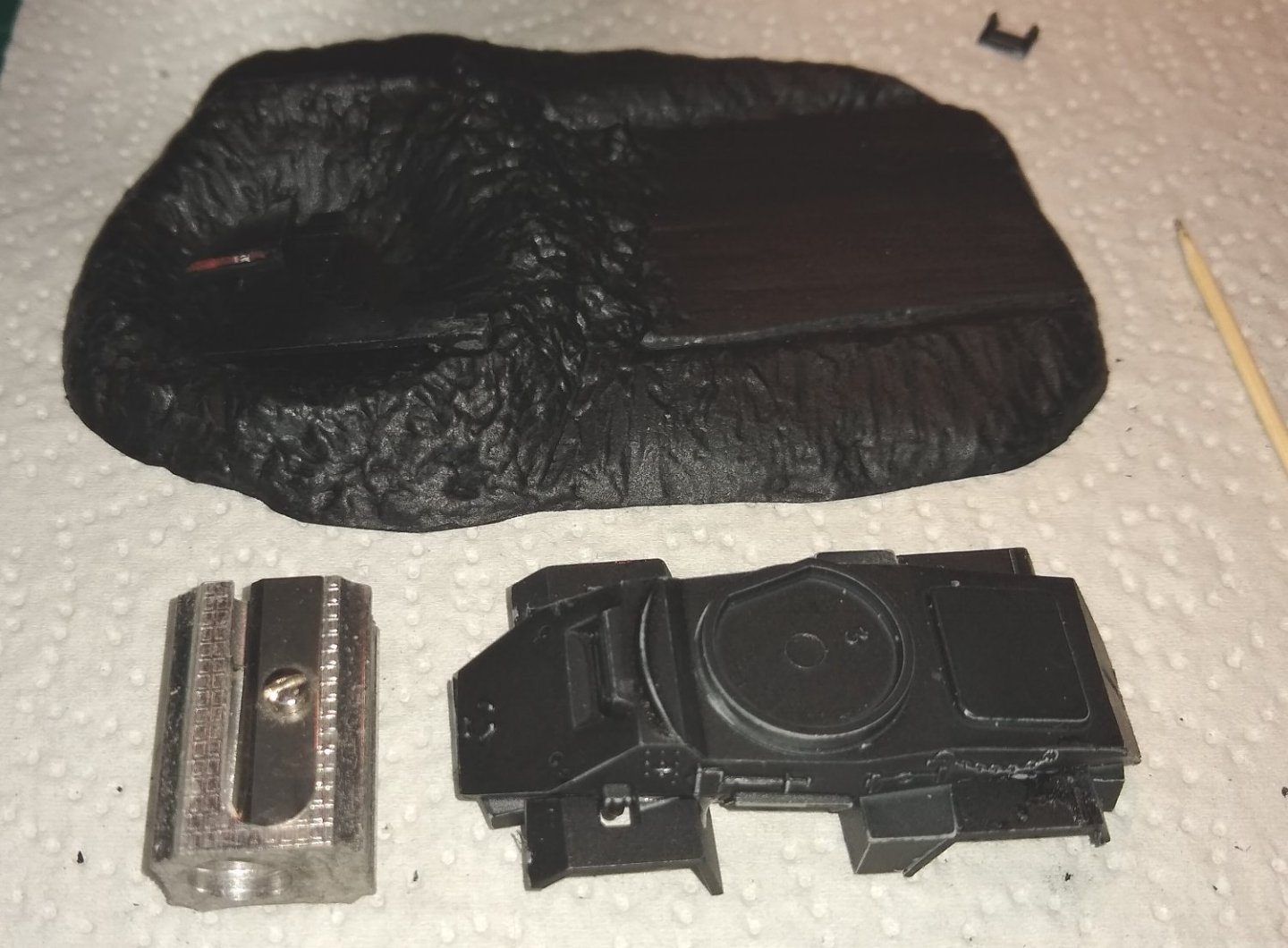
Below, the parts painted with a matt Black undercoat, and a different type of glue from the last kit (...Sherman tank) - I had hoped this glue would be less smelly than the Revell glue, but it wasn't - I now have Tamiya Extra Thin glue on order...3rd time lucky?

The kit really is quite small. Parts can be tiny, and painting of fine details will be a challenge.
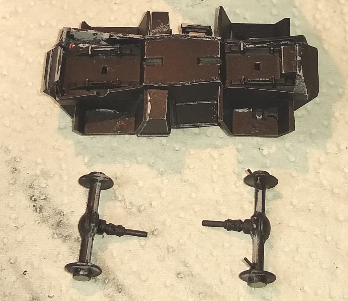
Below, the underside of the Humber with both wheel axles about to be fitted. The grey plastic showing through the undercoat is where I scraped off mould lines and/or removed paint for gluing.
My fingers found it difficult to position small parts for gluing. I tried tweezers but parts can ping out of those, so I ended up using some BluTack on a cocktail stick - that was a decent improvement on fingers.
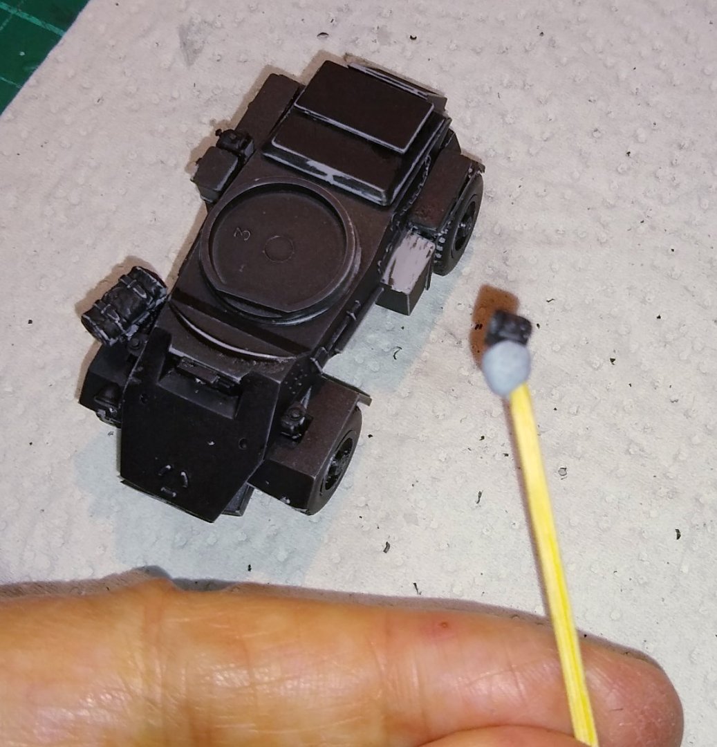
Starting to think about the composition layout of the diorama, plus the Commander getting ready for the paint shop. And the spare wheel which will be mounted on the front of the vehicle.
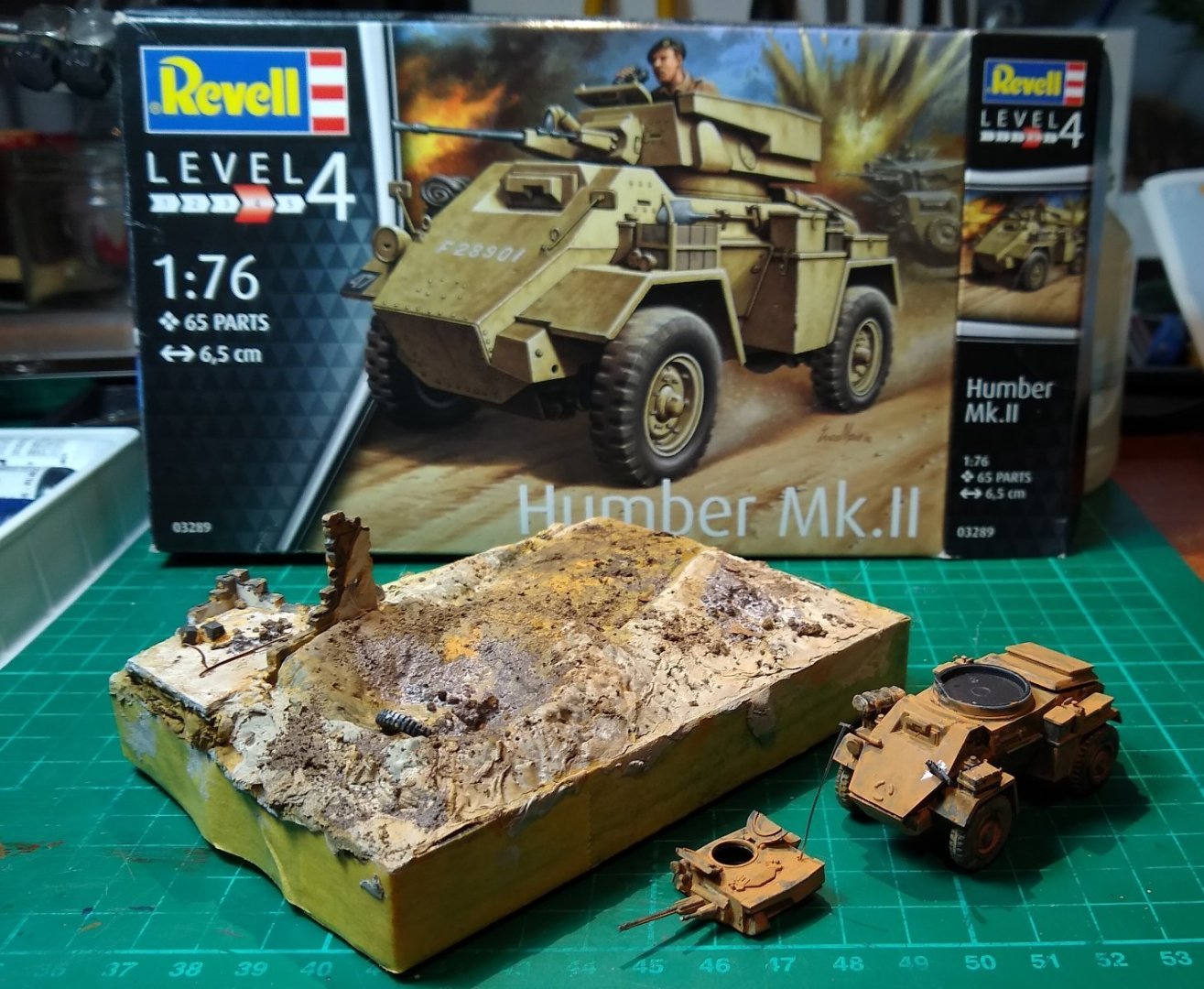
Now using up what was left of the tube of smelly Humbrol Filler putty to fill in the diorama area. This time I tried a breathing mask and it was surprising successful against the Humbrol putty. I have decided to extend the 'building' as I felt it was an important part of the 'story'.

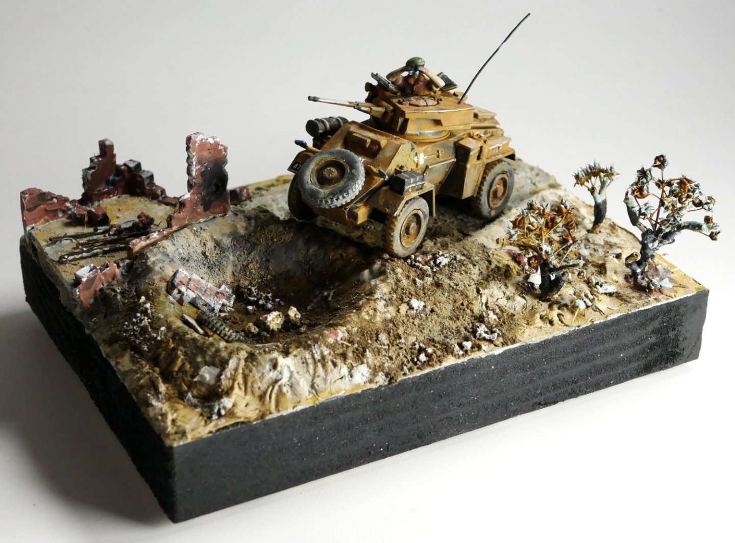
Where I've got to so far. Some colours added, plus some dirt. From my visits to the Middle East (...the closest I have got to North Africa) I remember desert sand as usually being close to white, and plenty of skree scattered about. I'll just fill the crater with rubble and stones rather than with (as I think Revell suggests) water. The scout car has also been give a base colouring. And looking at it again, I may add another corner to the building.
Final part in a week or so,
Regards,
Richard
-
As Chris says. She was designed to do a specific job and I imagine she did it well.
Your photograph of Chaconia is fine....and taken from a good angle. I don't think she is bad looking at all 🙂
Richard
- Canute, mtaylor and Glen McGuire
-
3
-
OC, Patrick,
Thanks for the comments.
I had a quick look at the history of the Sherman kit before I started building it and saw it had been about for decades. I didn't realise it was Airfix that had created the original moulds. I did see that Matchbox were involved somewhere along the line .... https://www.scalemates.com/kits/revell-03299-sherman-firefly--1324065 I'm now fascinated by the websites that keep track of a kit's history...they are doing a good job.
It's quite amazing how a product can be milked for so long, but if it has a market then fair enough. The details on the parts seemed reasonably sharp so I guess the original moulds have stood up well - they wouldn't make new moulds, would they?
For the few £s I paid for it, I'd say I got decent value out of it.
Regards,
Richard
Edit: Found the Airfix timeline also on Scalemates...https://www.scalemates.com/kits/revell-03299-sherman-firefly--1324065/timeline I wonder how Revell and Airfix can sell the same product, but are separate companies?
- mtaylor, Jack12477, Old Collingwood and 2 others
-
5
-
Thanks Alan,
It was a fun build and I learned a little about building plastic models. Looks like I'm probably off to North Africa for the next kit...it should be warmer there.
Richard
- Jack12477, Old Collingwood, Canute and 2 others
-
5
-
Having read through a number of the excellent plastic kit builds on this site I felt I should try my hand at it. I found the diorama compositions and weathering particularly interesting.
I built Airfix kits as a child but haven't been near one for decades. However RGL - Greg, on his Panard EBR11 build ....
https://modelshipworld.com/topic/35001-panard-ebr-11-by-rgl-finished-hobbyboss-135/ .... was kind enough to point me to Night Moves
https://www.youtube.com/@NightShiftScaleModels/search?query=guide .... for some tips.
I felt I should start at the bottom in terms of skill level required and financial outlay, so sourced the Revel kit below.
It comes with two paint colours, glue and a paint brush.

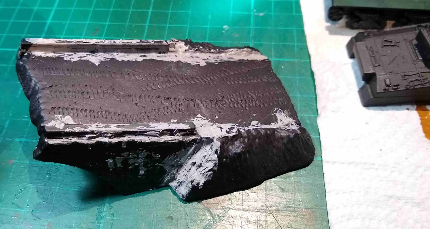
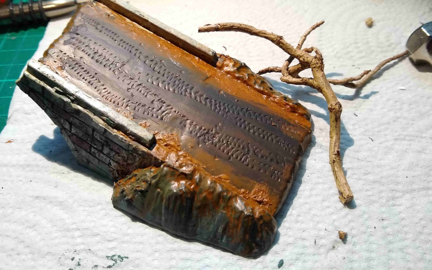
My attempts to scruff up (weather) the plastic and use a small chisel to simulate tank tracks across the bridge...those tracks eventually mostly got lost after I dumped a lot of soil on the bridge.
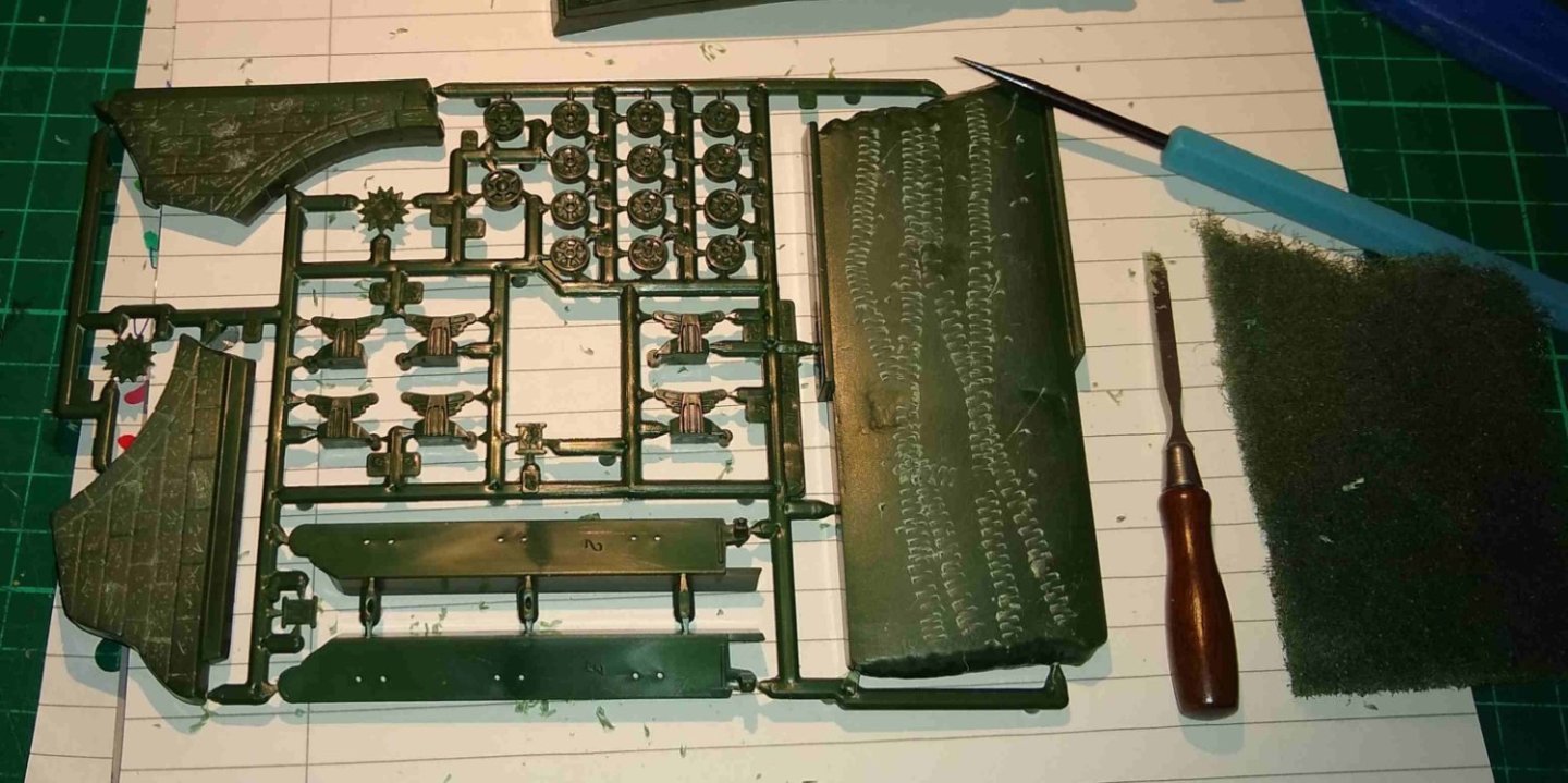
After washing the plastic in warm soapy water (to remove mould releasant) I applied a coat of matt Black spray paint.
Drilling holes in the 'wheels' so they would sit properly on the axle stubs.
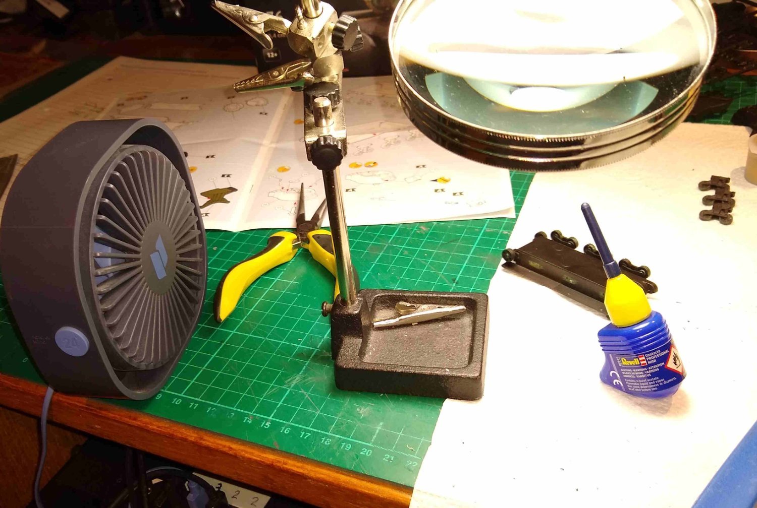
As an aside, the Revell glue smelt really bad, as in toxic bad. The USB fan to the left was used to try to direct the fumes away from me, plus an open window.

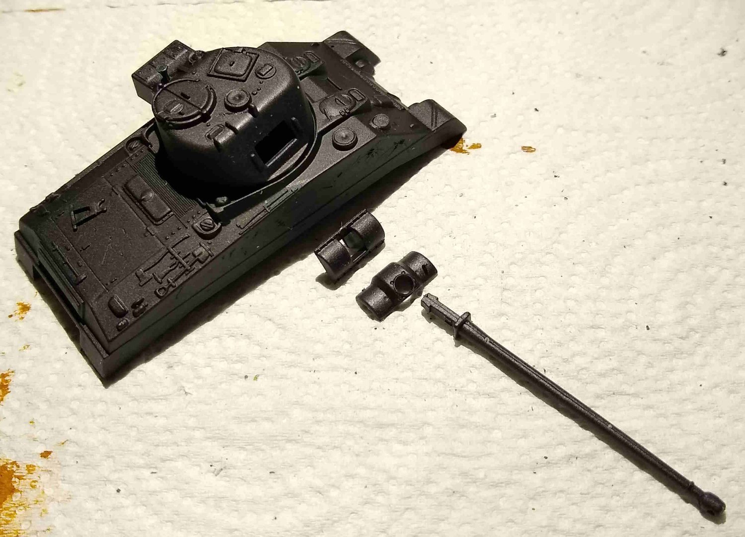
The cannon parts about to be assembled on to the tank body.

And talking of toxic smells, the Humbrol putty (to the right) was even worse.
Filling in cracks and gaps with the putty.

And starting to add a bit of colour, plus a piece of dead Ivy that would become a 'tree'.

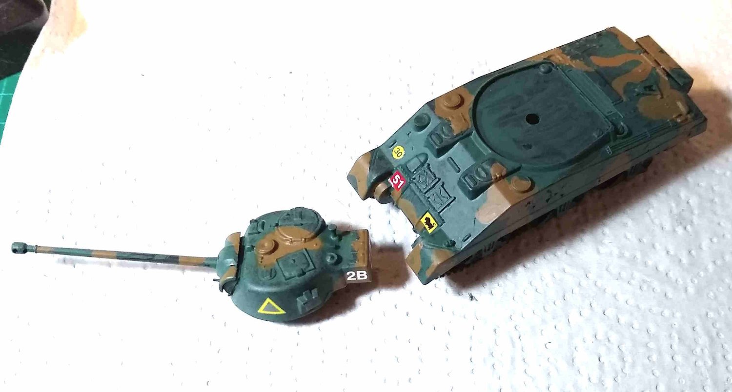
Tree planted, and tank (now camouflaged) eyeing up the bridge.
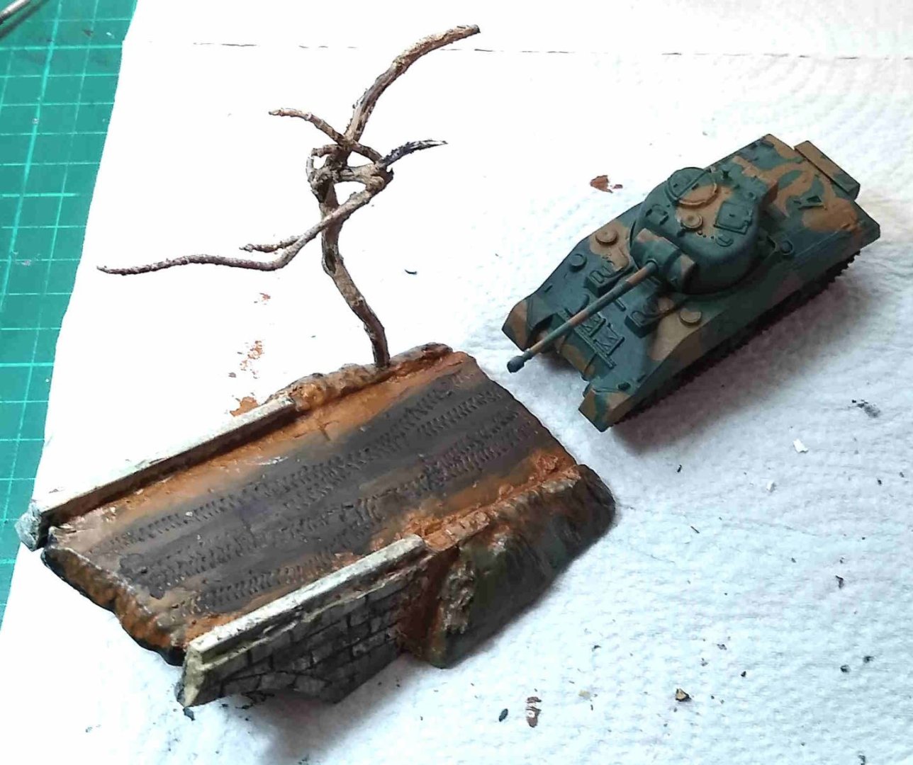
Transfers added. They are for the '2nd Fife and Forfar Yeomanry', Rheinland, 1945.

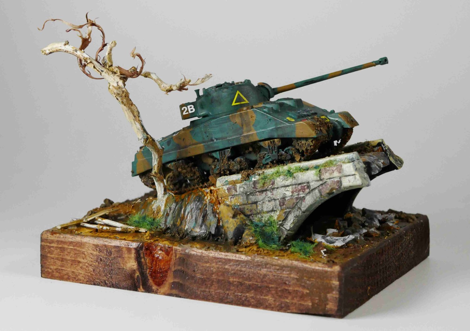
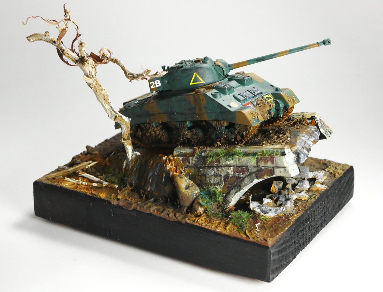
And the finished article. Yup, I threw every colour known to man at the diorama, and even a bit of plastic grass 😉
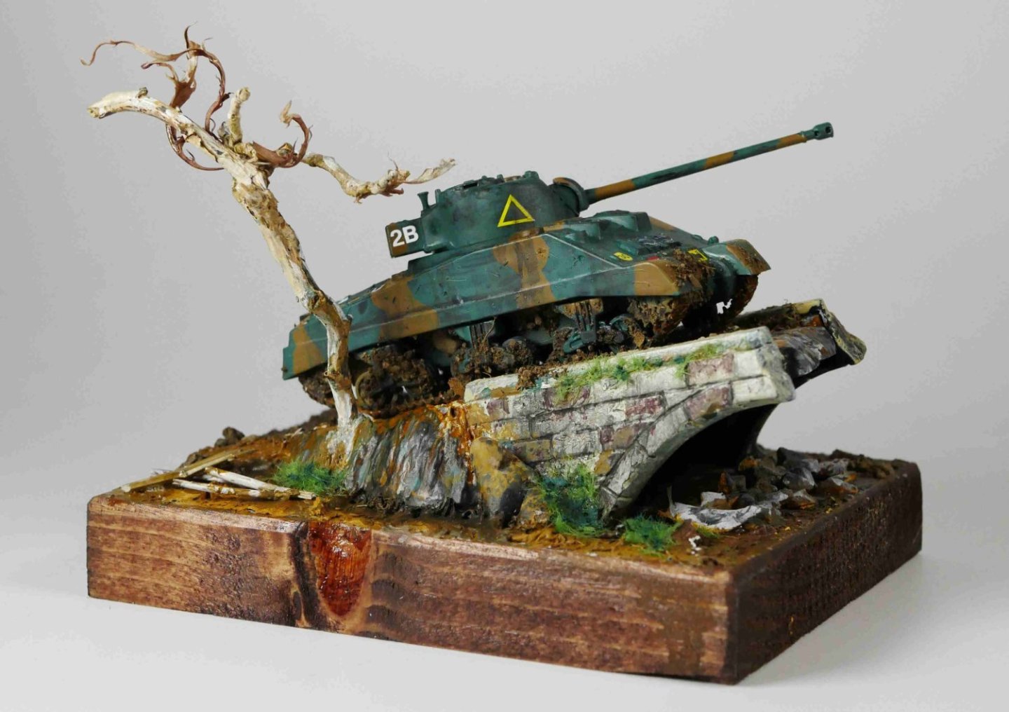
Above, I took quite a lot of pics of the finished diorama, but decided on this one since it shows the tank mostly in profile, with the tree adding balance on the left. Part of a knot fell out of the base half way through, but I feel it adds character...at least that is what I am telling myself.
Edit: I painted the base Black.

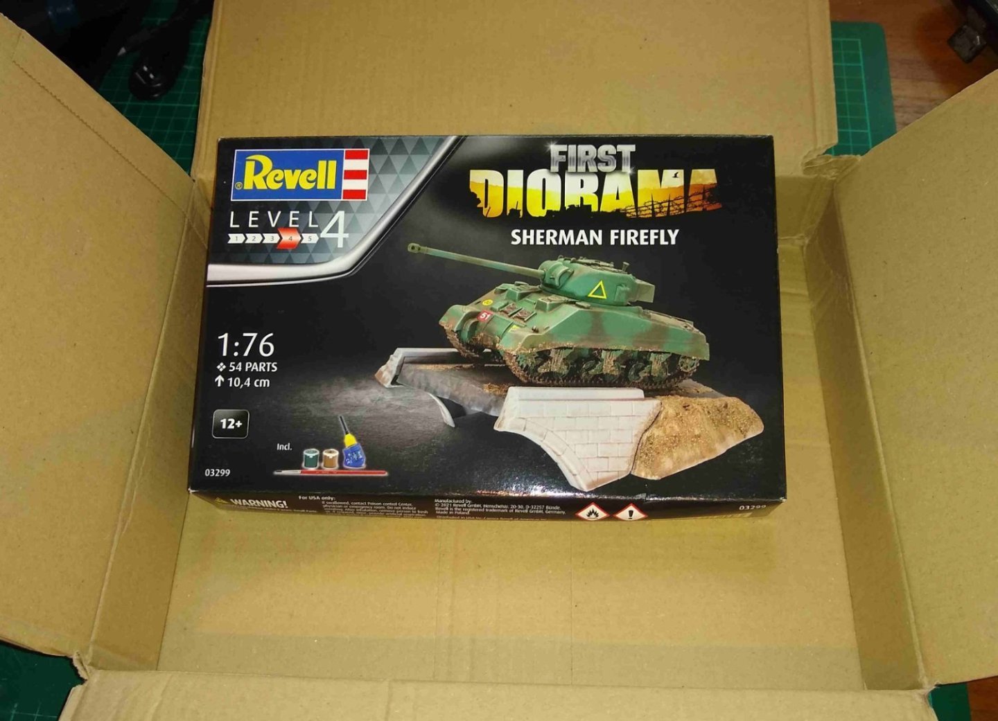
And being on a roll, I then decided to then buy the kit below.

Regards,
Richard
-
Yes, Egilman...the Shaper!...I've had my eye on it for a while.... who knows? 😉
I'm currently trying my hand at small, beginner-level military dioramas....very beginner level. It's many decades since I built plastic models and things have moved quite a bit since then....especially the 'weathering' of them, which is fascinating....but its a long learning curve. Anyway, winter is arriving here so the machine shop will see much reduced activity till Spring.
Thanks again for the comments and kind words,
Richard
-
-
Dear MSW,
I've just realised I entered my 'PM Research Drill Press by Rik Thistle - FINISHED -1895 - 1:12' ( https://modelshipworld.com/topic/35068-pm-research-drill-press-by-rik-thistle-finished-1895-112/#comment-1001205 ) in 'Modeling tools and Workshop Equipment' .... it should have been in 'Non-ship/categorised builds'.
How can I correct this?
Thanks,
Richard
-
The set of 4x pin vices that Ryland mentioned earier is useful since it allows your most commonly used drills to be left in each vice. And finger tightening is sufficient. However, once in a blue moon, the nut jams on the collet and is a devil to get off. The only other drawback is the other end of the pin vice can get a bit sore on the fingers if doing a lot of rotations.
The vice with collets hidden inside is much more pleasant to use (ie rotate) but, as mentioned, sometimes needs a good bit of force to grip the drill bit. It is also slightly bulkier.
I have both types...I'd say it's a 50:50 split decision, depending on the use case.
Richard
- mtaylor, Ryland Craze, Canute and 1 other
-
4
-
Hi Paul,
Thank you. Yes, the slot for the drift was a little challenge.
I should really add some Accessories to the drill eg Drift, Vice, Clamps for the ground level T-Slots, lubricant can etc....one day 😉
I've now run out of ideas what project to do next. I think I'm happiest with a max of 6 months or so project length, nothing too large (the Stuart Beam was as about as big as I'd go), I find Aluminium and Brass are more pleasant to work with...and I'm running out of shelf space in my study.
I've got a few books of model plans so will have a look through those and see if anything catches my eye.
All for now,
Richard
- Canute, thibaultron, mtaylor and 1 other
-
4
-
-
Hi all,
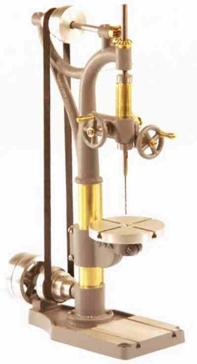
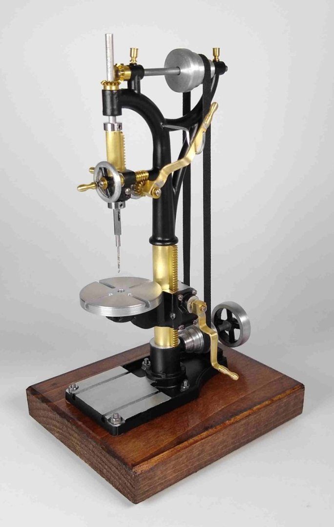
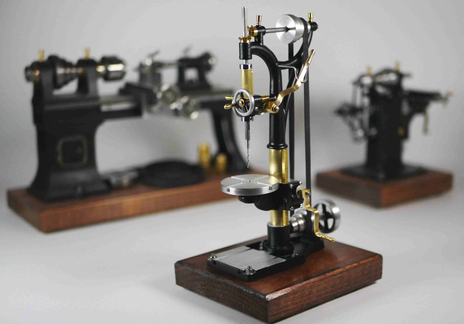
A final post to wind up the build of the PM Research Drill Press model shown below.
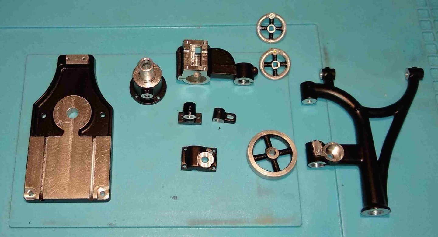
My parts, back from the paint shop. I had run out of my usual Satin Black spray and couldn't find the same brand with a reasonably short delivery time, so went with a different brand. I don't like it as much, but it will do for the time being.
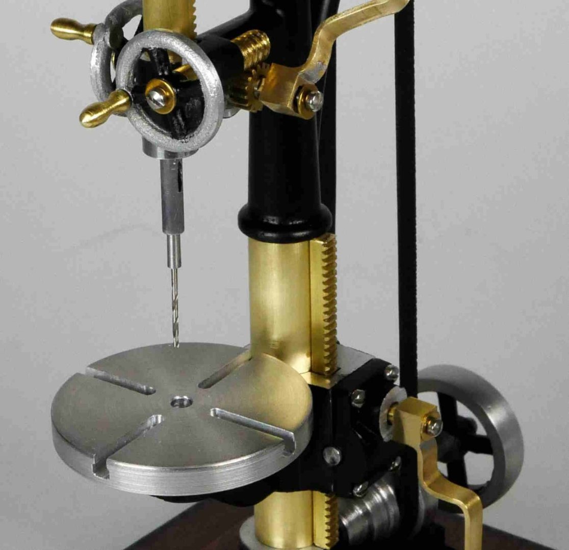
The drill, ready for some action. All the levers, gears etc work. I guess I should have made a small vice for the table?
The finished model.
And now moved to the 'workshop' to assist the Stuart Lathe and PMR Milling machine.

The build was reasonably short but had enough little puzzles to keep my mind working. I'm really not sure what to do next - I've now done a couple of steam engines, three workshop machines and, earlier, two ships/boats. So off to have a good think and look around 🙂
Thanks to all for the Likes etc.
Best regards,
Richard
- Roger Pellett, GrandpaPhil, Altduck and 7 others
-
5
-
 5
5
-
Hi Paul,
Good to hear from you.
I watched the first few parts of Joe Pie's build and just had to try to follow his treatment of the base since it seemed so right. It was a bit taxing but worth doing. But I didn't watch his later episodes since I felt I should do my own thing, rightly or wrongly ;-).
I've realised that very small taps are most vulnerable to lateral forces ie I always try keep them totally co-axial with the hole, usually using a home-made pointed locator in the chuck wrench top. With the tap's deceptively small root diameter it's amazing that they do as well as they do. I have a spray bottle with Paraffin in it always at hand for use on Ali.
Certainly, with Mild Steel say, I try to make the tapping hole a tad bigger.
Regards,
Richard


Churchill MkVII tank by Rik Thistle - FINISHED - Tamiya - 1:35 - 1944
in Non-ship/categorised builds
Posted · Edited by Rik Thistle
Chris,
King Tiger - I'm guessing it was the Tamiya model?....it looks quite the thing,, and 1:16 scale.... https://www.tamiya.com/english/products/56018kingtiger/index.htm
From what Tamiya writes the tank sounds were authentic and impessive.
Looks like it still available? .... https://www.modelsport.co.uk/product/tamiya-king-tiger-tank-with-option-kit-13599 ... for about £700, phew. Maybe one day 😉 Edit: I see it may be a fully assembled die cast model., so probably not your one Chris.
Richard