

Rik Thistle
-
Posts
808 -
Joined
-
Last visited
Content Type
Profiles
Forums
Gallery
Events
Posts posted by Rik Thistle
-
-
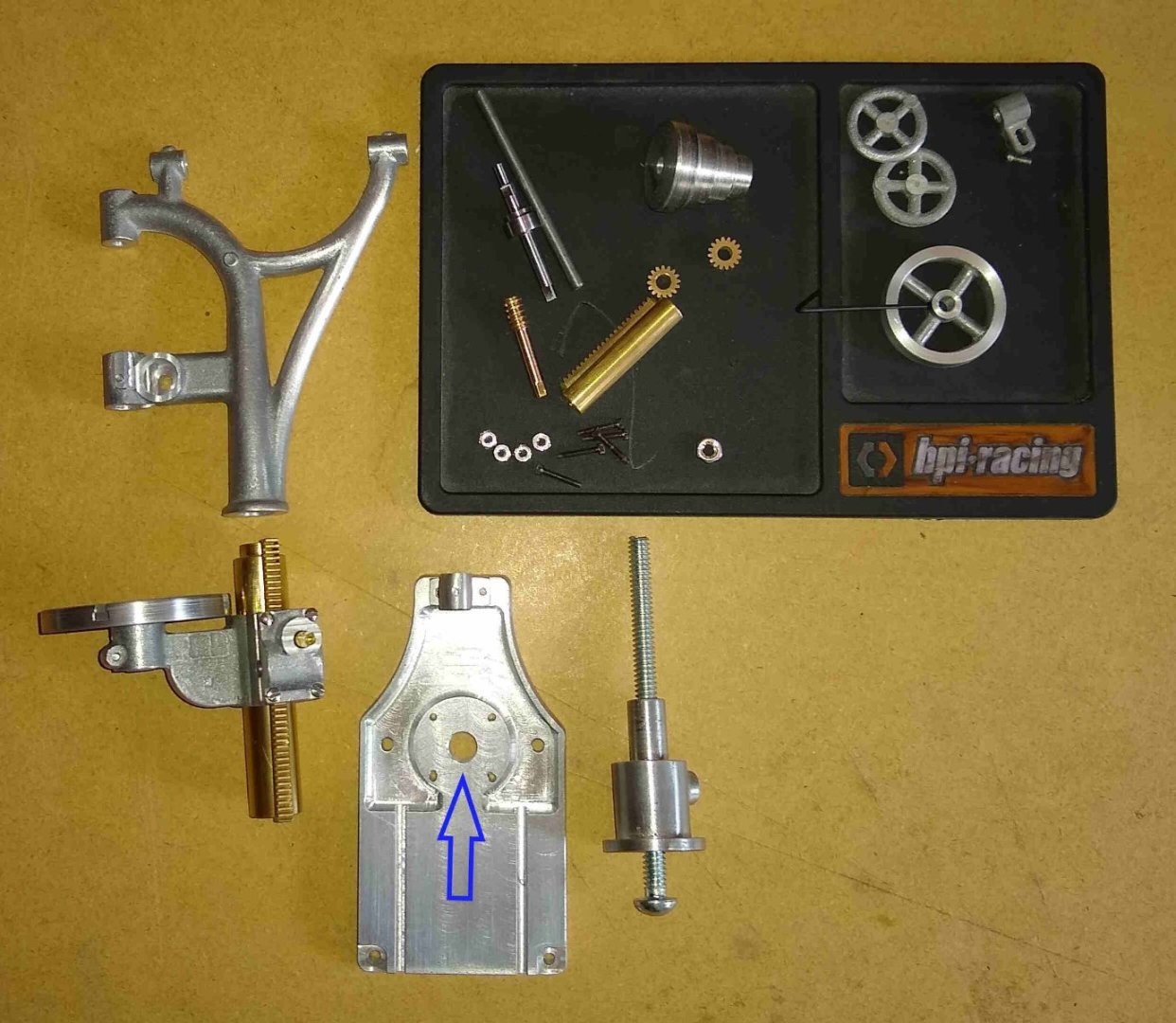
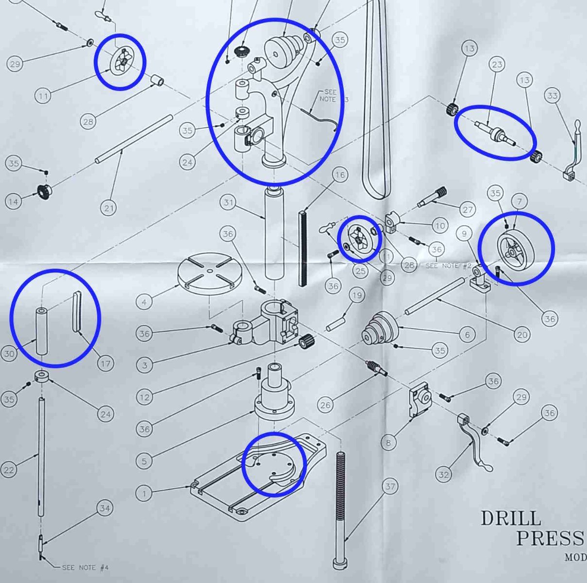
Some further updates on the model PM Research Drill Press parts that I have been working on for the past couple of weeks or so.
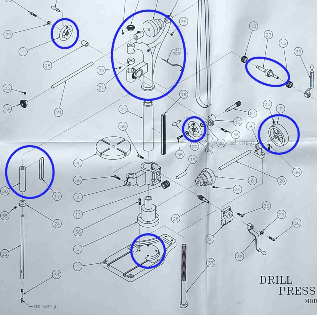
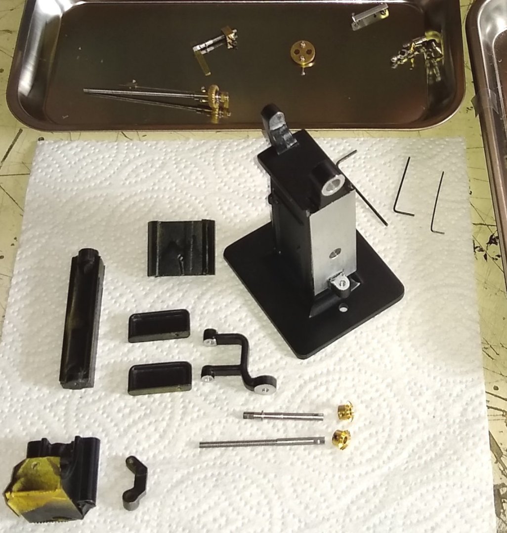
Below, ringed in blue, are most of those parts.
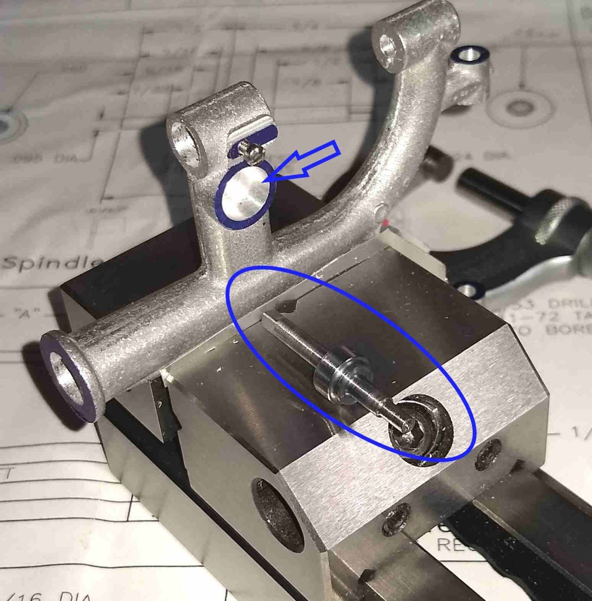
Below, the Mild Steel Spindle Feed shaft. Quite a straightforward part, with square drives either end, one for a small hand wheel (Pt 11) and the other drive for a large lever (Pt 33), which is disengaged, for safety reasons, when the drill is powered up.

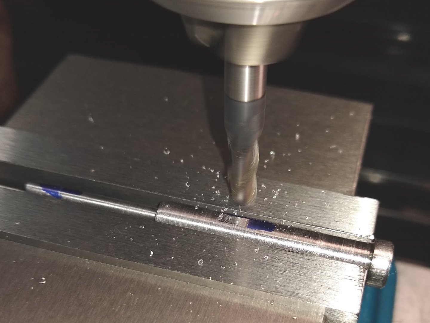
After turning one end of the shaft down to diameter on the lathe, the four flats at that end were produced on the mill.
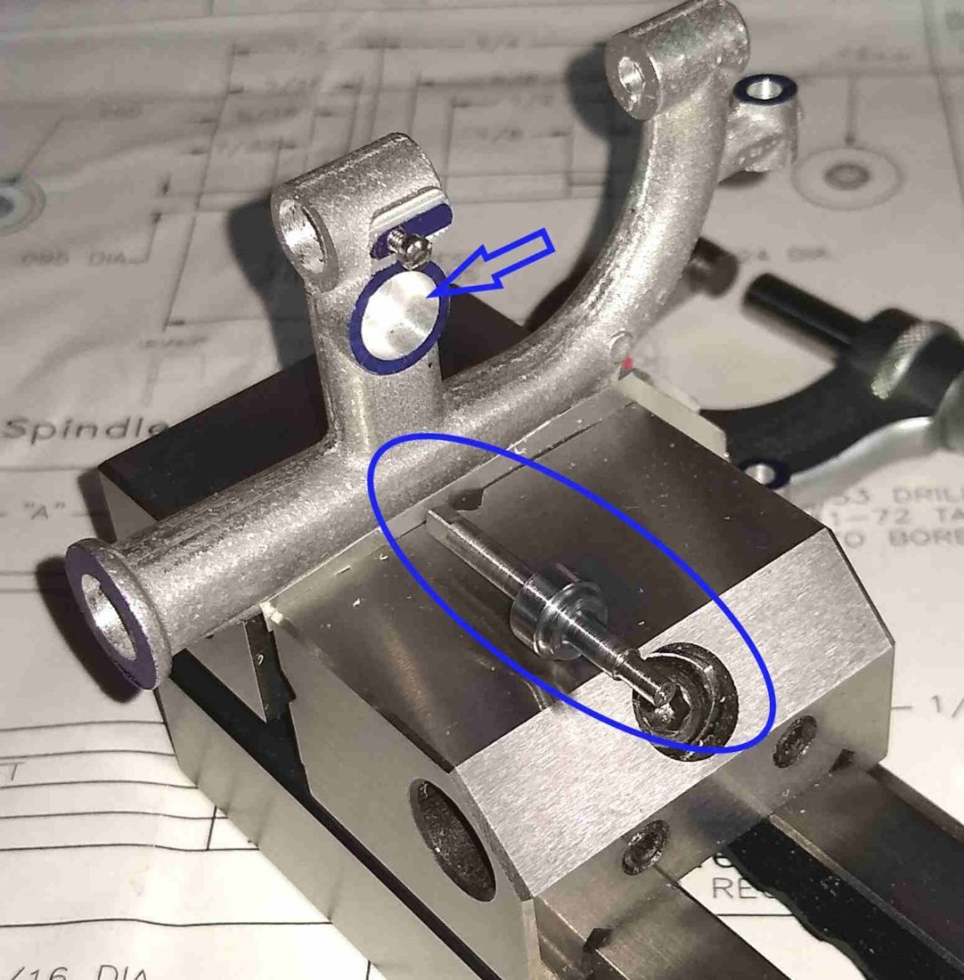
A quick test of the turned sizes by fitting the shaft in to the Frame (Pt 2).
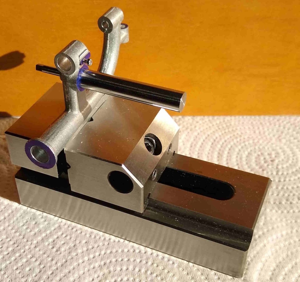
The finished shaft is indicated below, as is the opening it fits in to.
The shaft assembled with the two brass gears that will be press fitted on to it or, in my case, probably Super Glued 😉
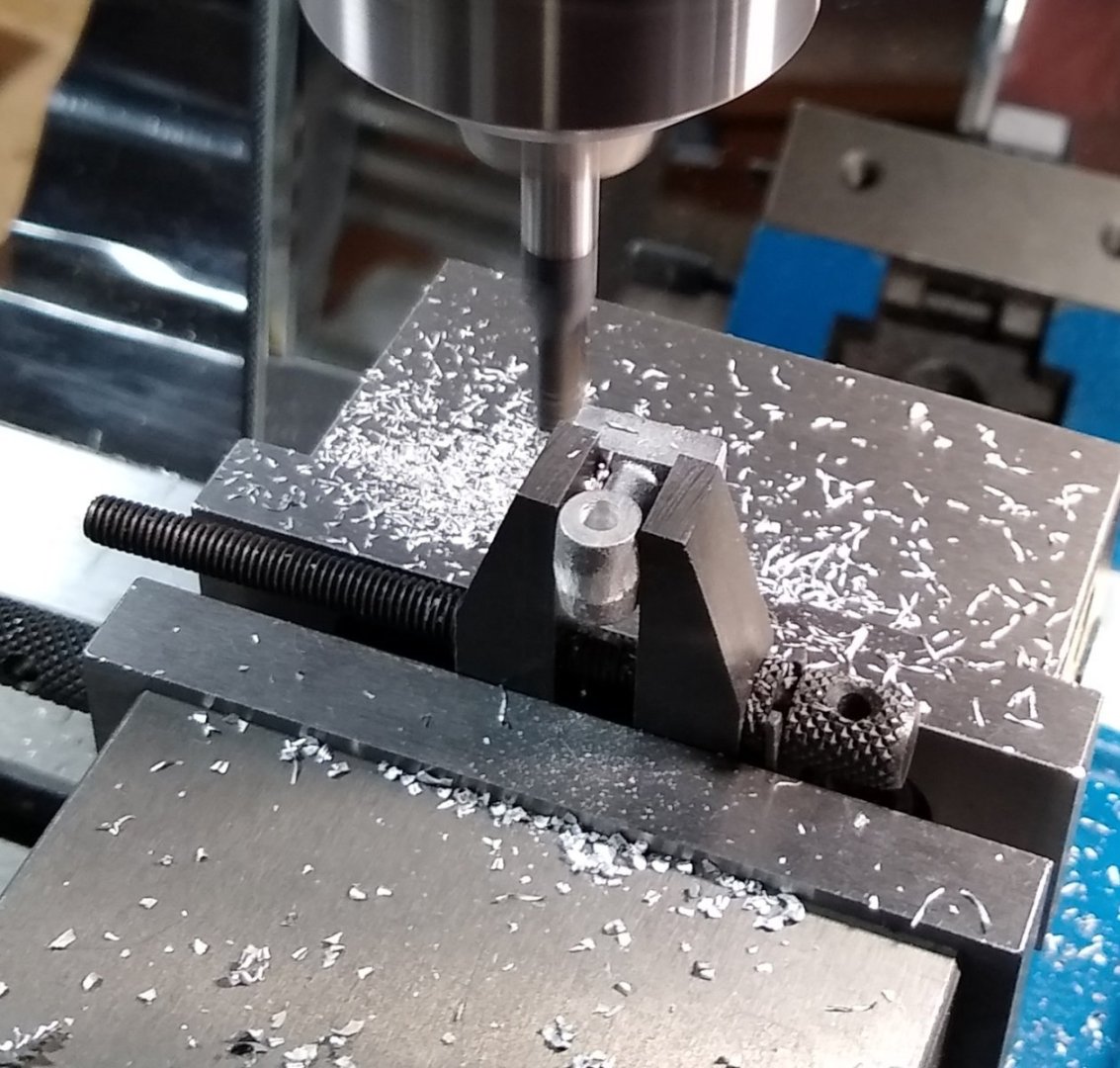
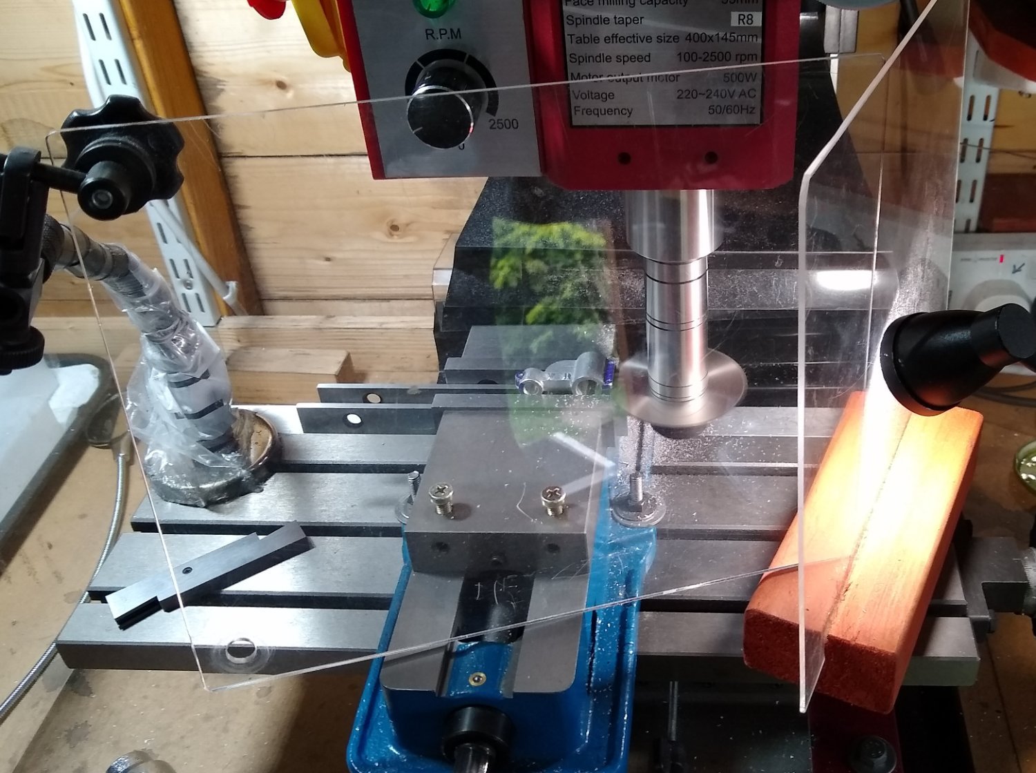
Pt 17, the Spindle Rack requires a square slot to slide in as the Spindle Sleeve moves up and down. The slot is about 1/8" square, so I used a long series 3mm end mill to remove most of the slot material before getting the square needle file back to work to finish off the slot.
The milled slot, just before the needle file starts forming the square corners.
A sub-assembly of the shaft, two gears and Pt 27, the Worm Feed Shaft.
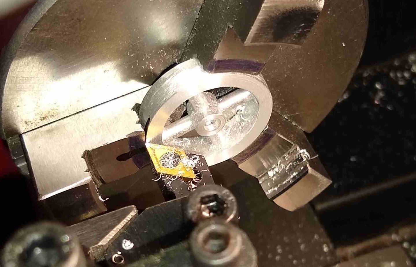
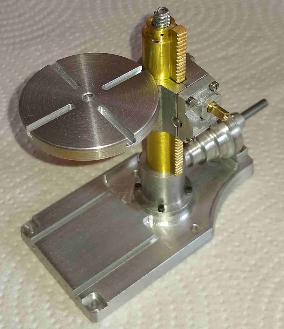
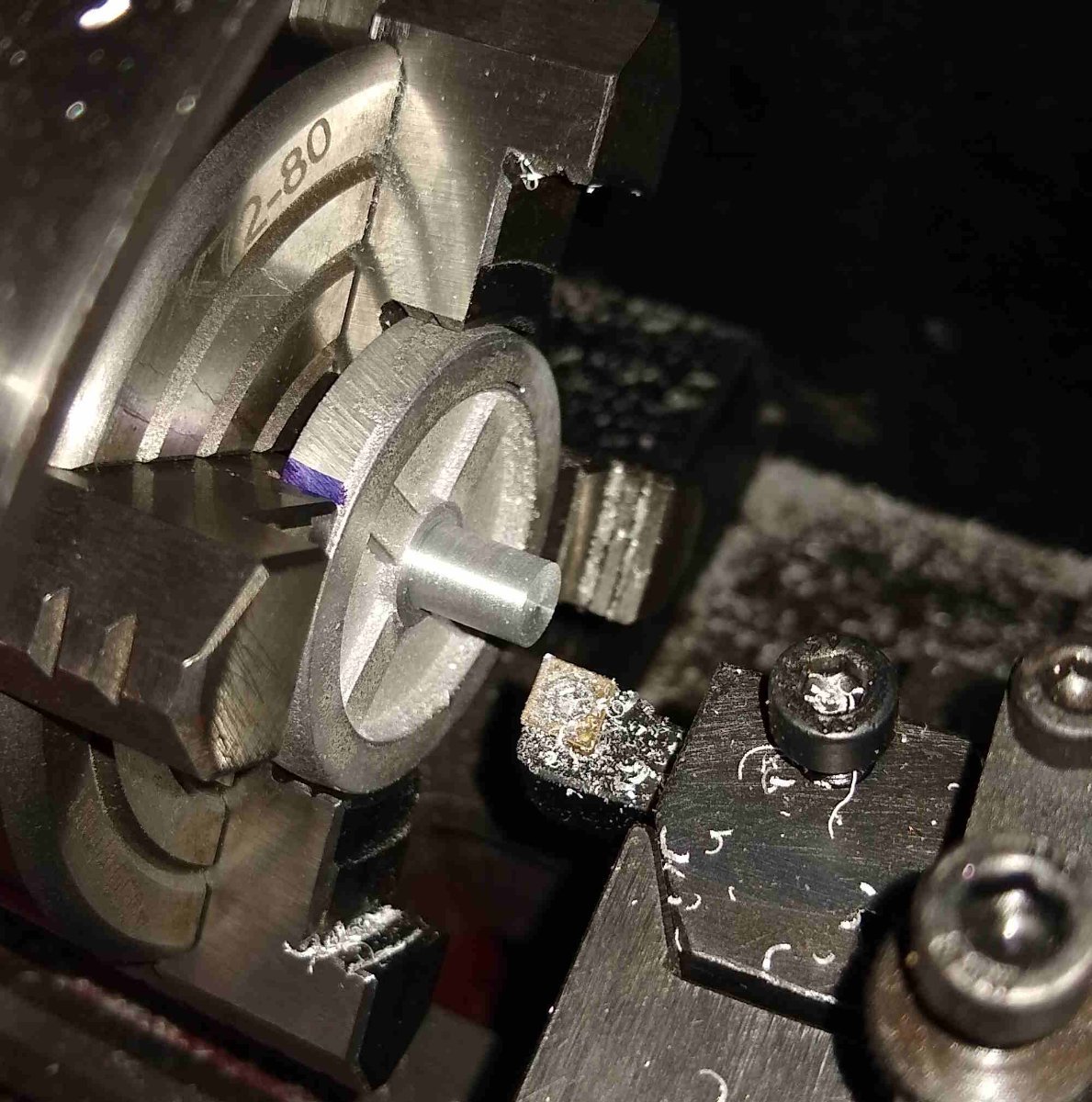
Below, is the main drive pulley. This is where power is initially fed to the drill when it is in a functioning machine shop.
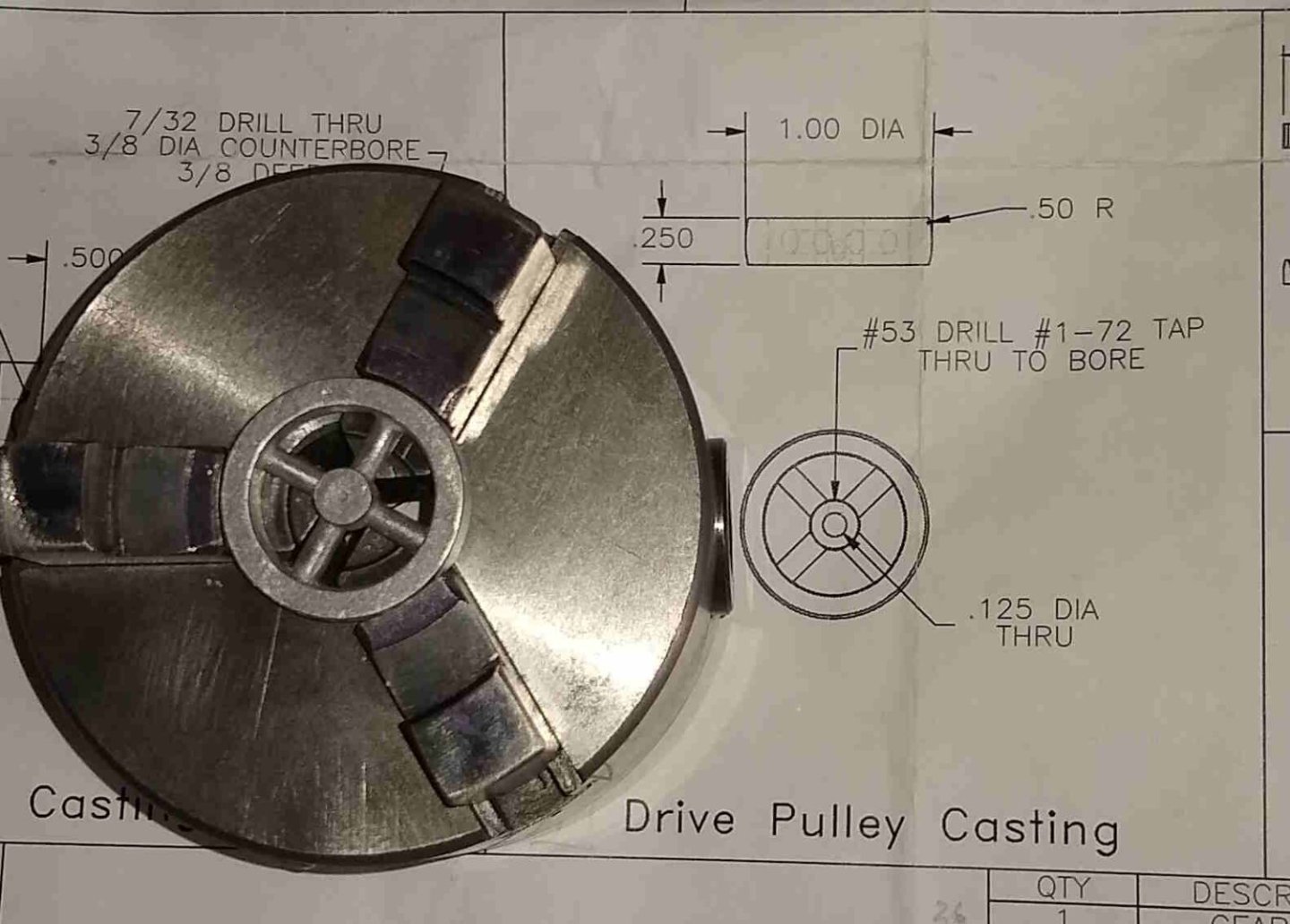
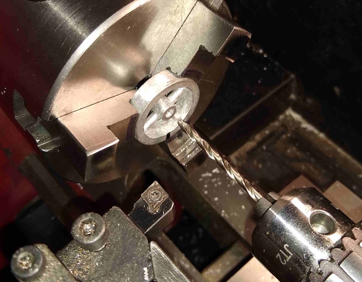
The only way I could find to hold the pulley was to use the 3 jaw chuck, with the reverse jaws. The jaws sat slightly below the width of the pulley so that allowed me to skim the faces flat.
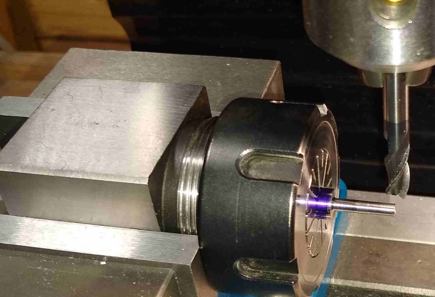
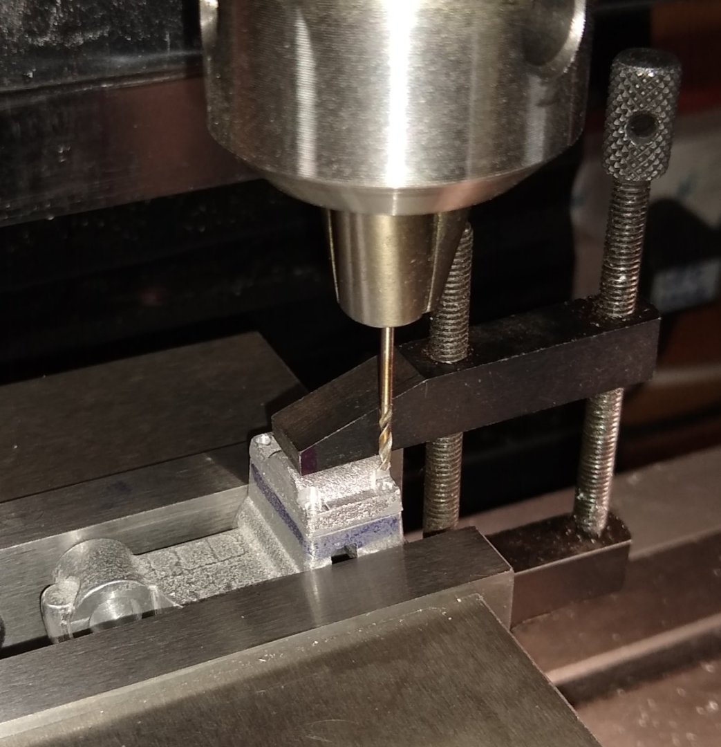
Slightly out of order, but the 1/8" hole is shown being drilled below.

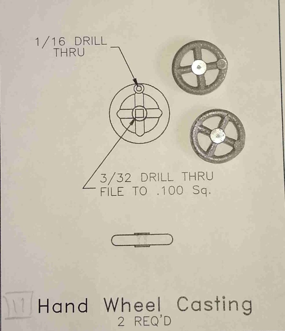
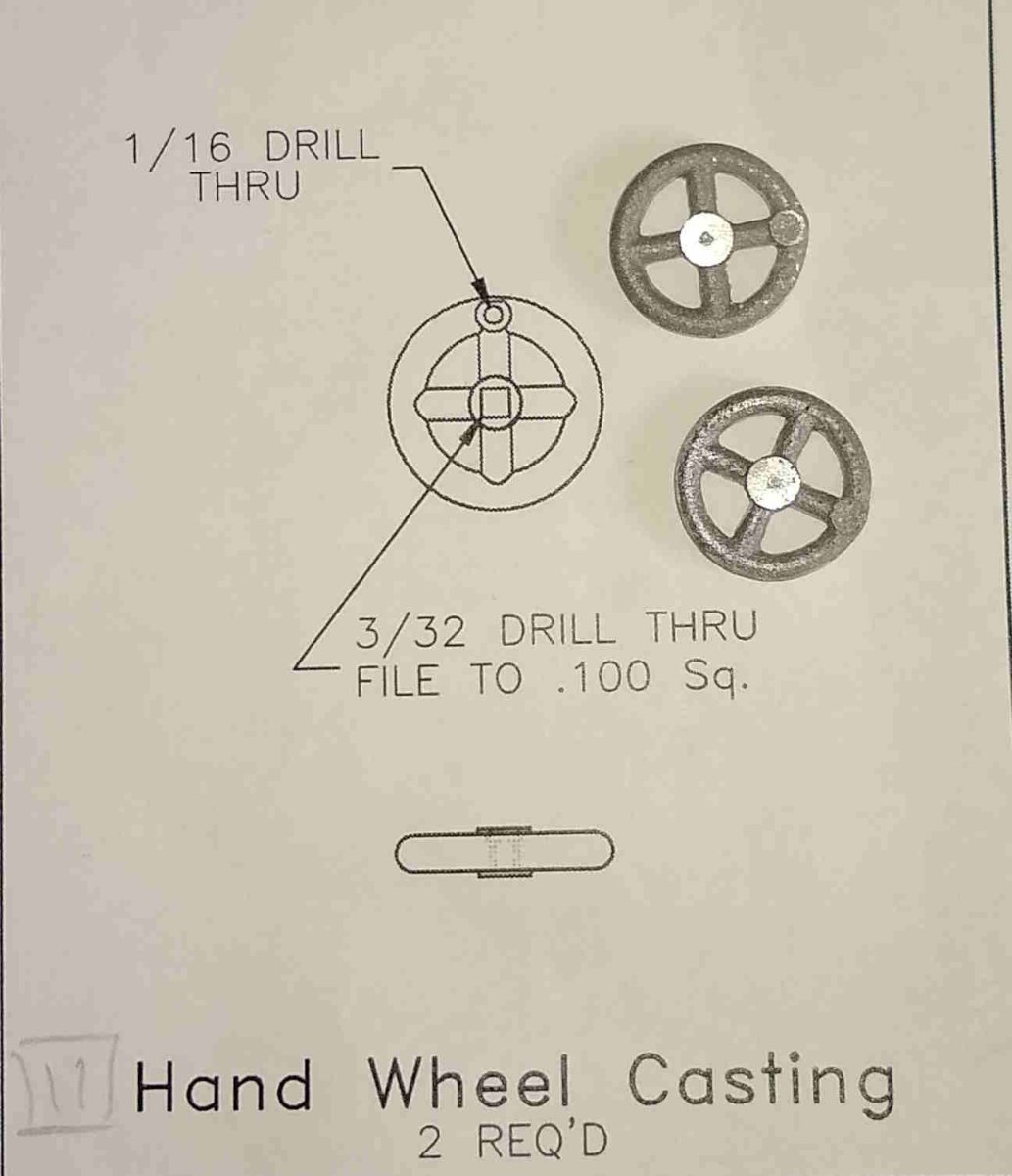
There are also a couple of small, delicate cast hand wheels that need a couple of holes each. Again, no problems here as long as they were handled/clamped lightly.
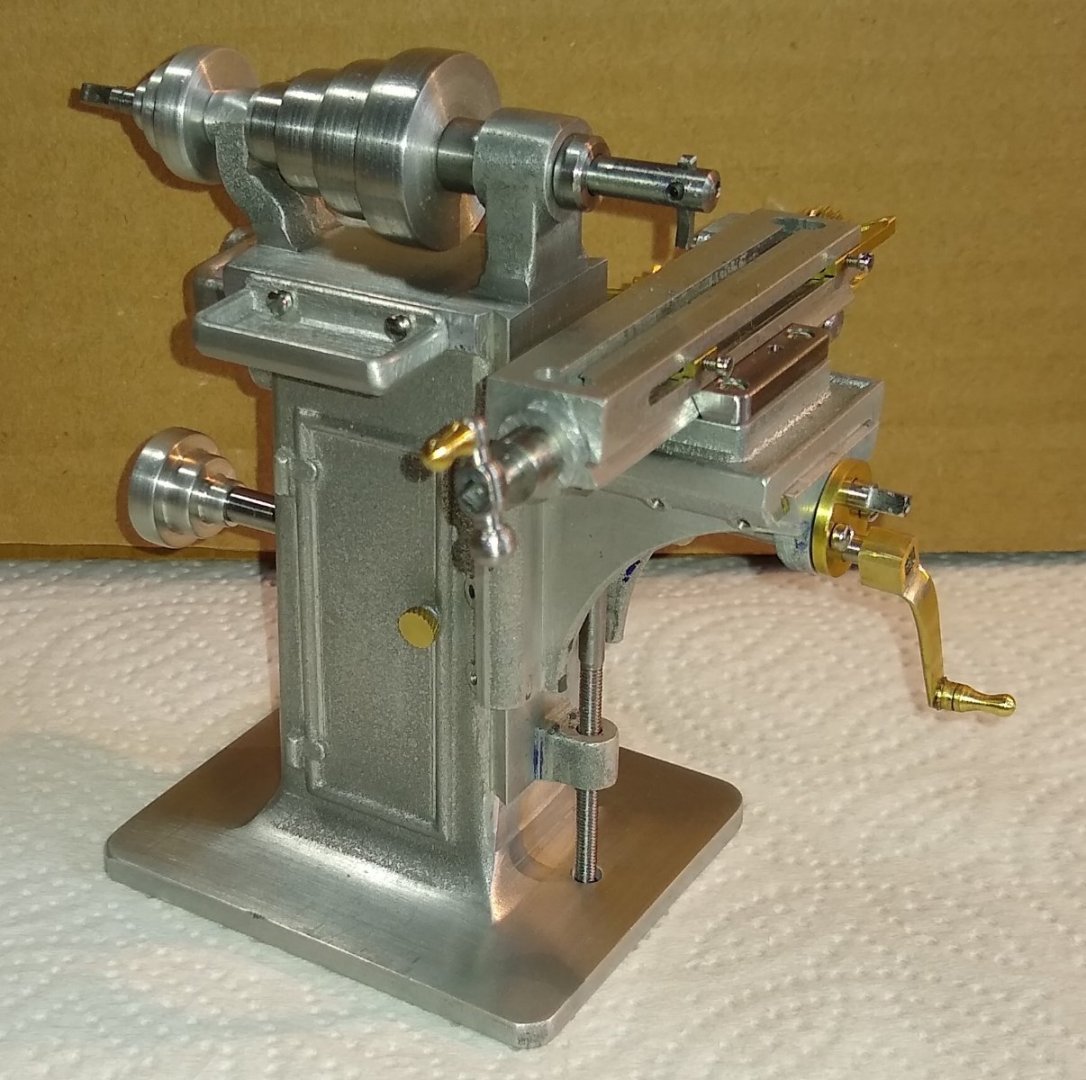
There is a 3" long slotted head screw (#10-24). It attaches the Column Base to the Frame. The only way to tighten this screw was to undo the 4x screws that attach the Column Base to the main Base ...it quickly became a hassle undoing these 4x screws each time I needed access to the slotted head of the #10-24 screw, so I decided to drill out a 6mm dia hole in the Base to allow a reasonably sized screwdriver blade access.

Most of the parts made so far. The 6mm hole in the base is indicated by the blue arrow.
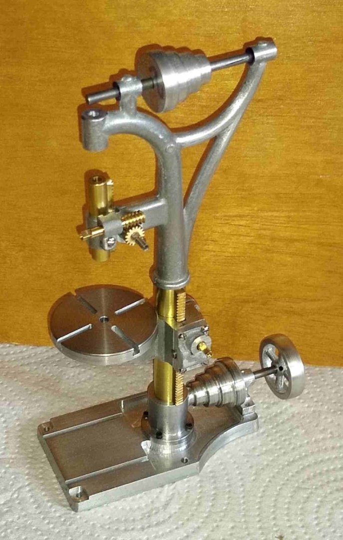
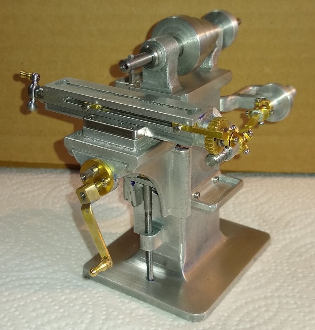
And the final pic for today is an assembly of the parts made so far. The drill is beginning to take shape. It's not too unpleasant to look at....almost Art Nouveau in style?
That's it for today. Back soon.
Richard
- mtaylor, thibaultron, king derelict and 3 others
-
 3
3
-
 3
3
-
Hi all,
My latest updates on the Drill Press progress.
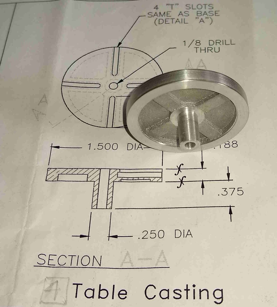
For the past week or so, I've mostly been concentrating on two main items, Pt 4 the Drill Table and Pt 2 the Drill Frame.
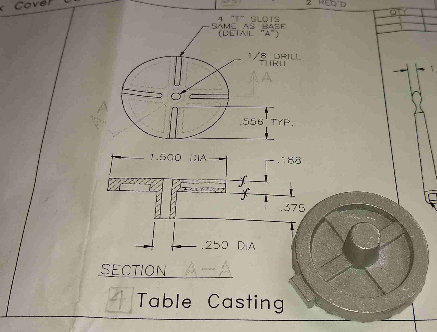
The Table was fairly straightforward to machine.
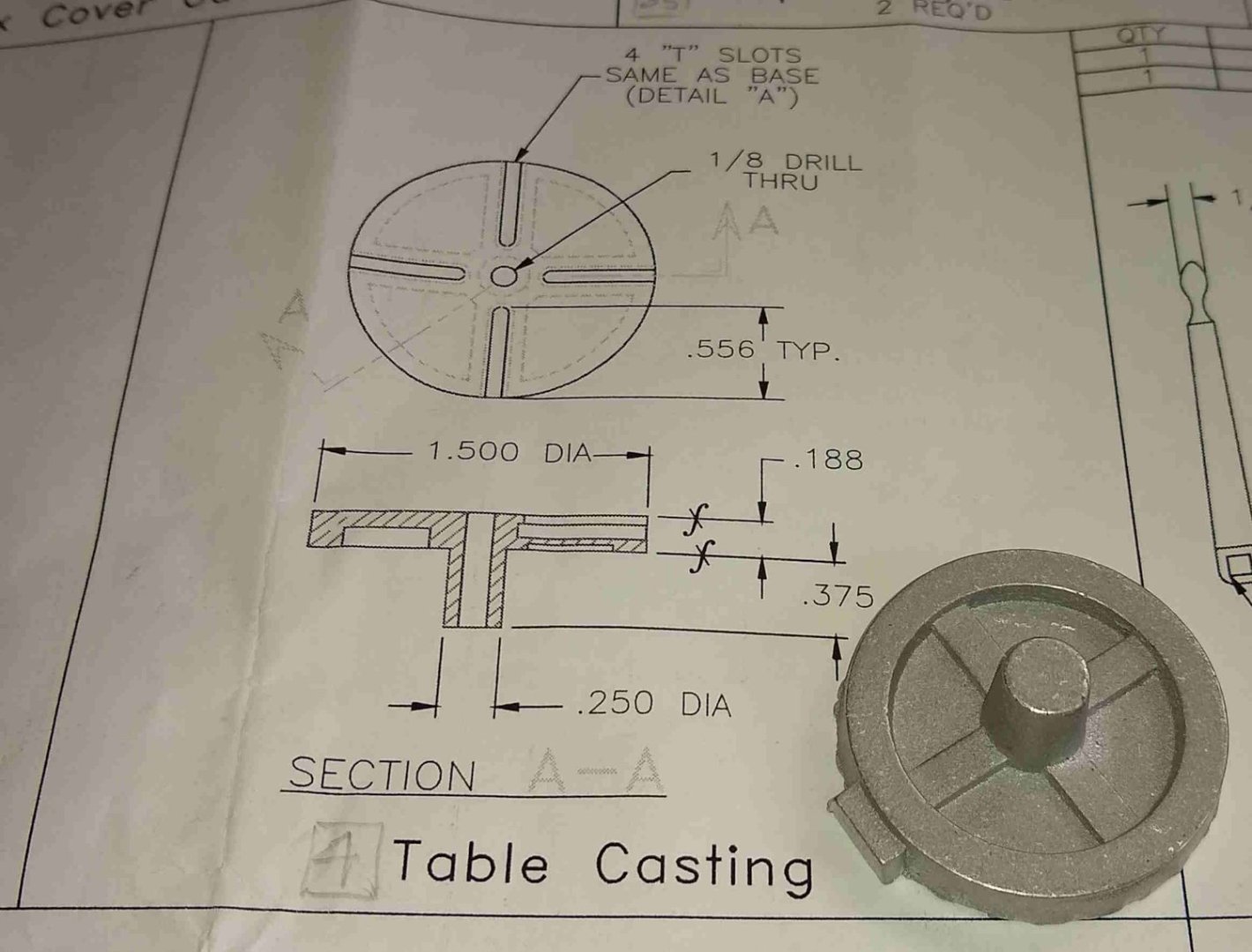
Cleaned up casting flash etc first. The casting's cylindrical stub was tapered, so I clocked the 1.5" diameter in the 4-jaw and then skimmed the stub till it was to size. Then held the stub in a collet, cleaned up various faces and drilled the 1/8" hole.

Ready for the T Slots.

Using the same T Slot tool I used on the PM Research model Milling Machine, but firstly removing most of the material with a 2mm end mill.

And fitted to the Drill sub-assembly
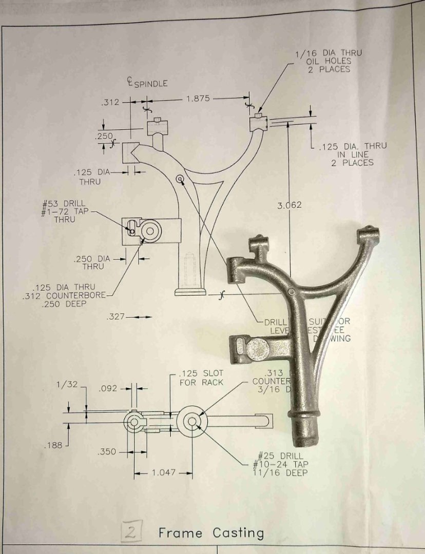
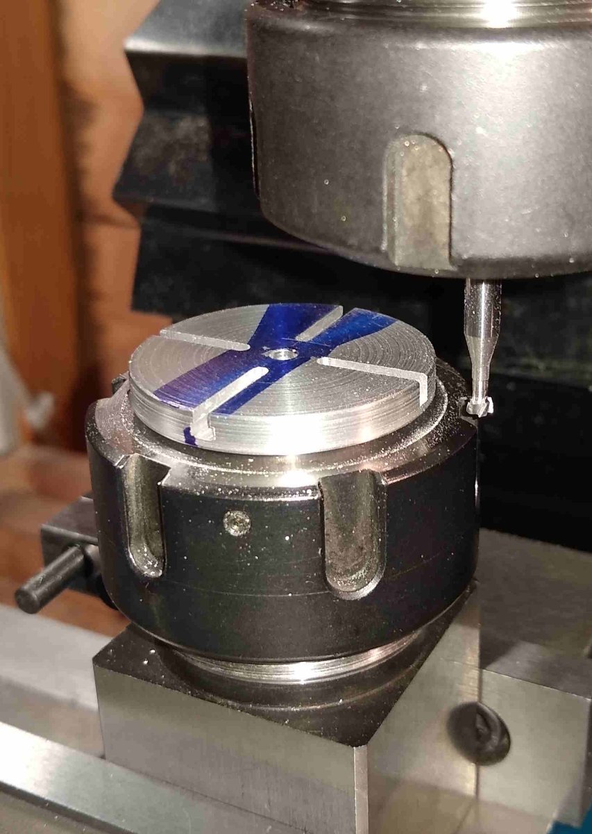
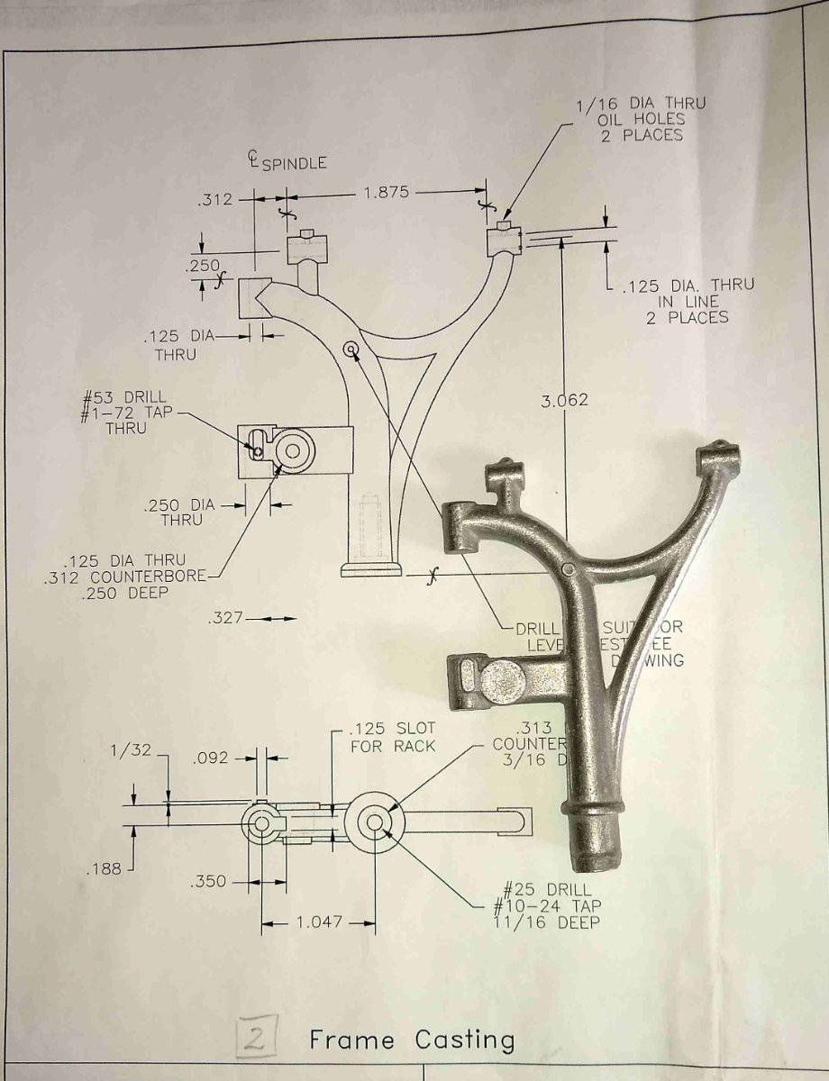
Next was probably the most difficult part of the whole drill to machine, the Frame Casting.
The big question was how to hold it. After careful inspection I noted that the two thinner legs were approximately close to the same thickness. After some careful hand filing, I brought the two legs down to about 0.200" thickness (IIRC) ready for clamping.

I had noticed that some other builders had built a jig to hold the Frame....but I figured my toolmakers clamp would serve much the same function as a jig ie it would secure it as well as reasonably could be expected and the toolmakers clamp could easily be rotated in the X, Y and Z planes in the mill vice to present whatever feature needed machining. I added a couple of pieces of thin Aluminium foil on the legs to improve grip.
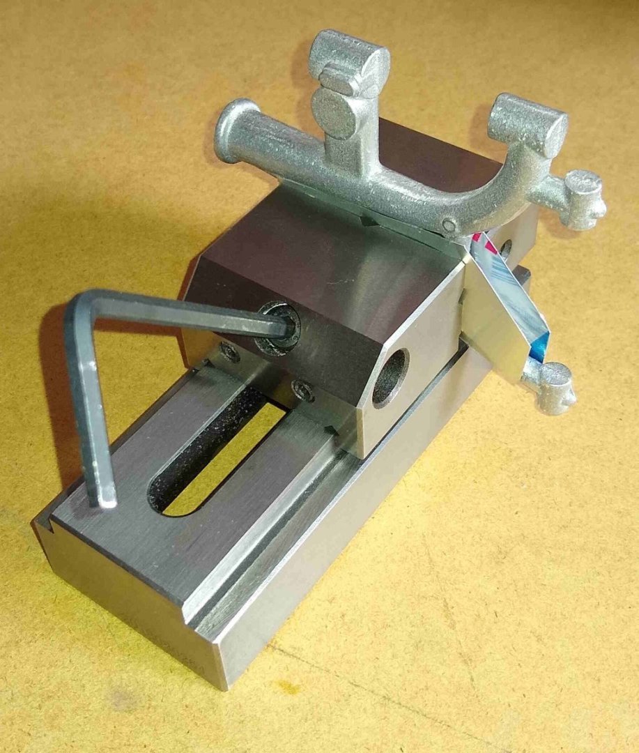
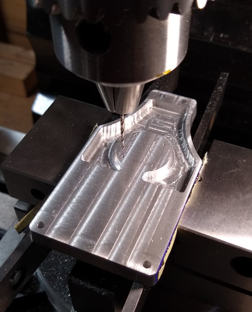
Milling flat and drilling as many features as this orientation allowed.
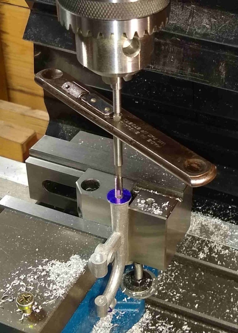
Tapping the #10-24 hole for the main support screw that retains the Frame on to the Column.
Another orientation. Machining most of the features for the Spindle Feed Shaft and its associated parts.
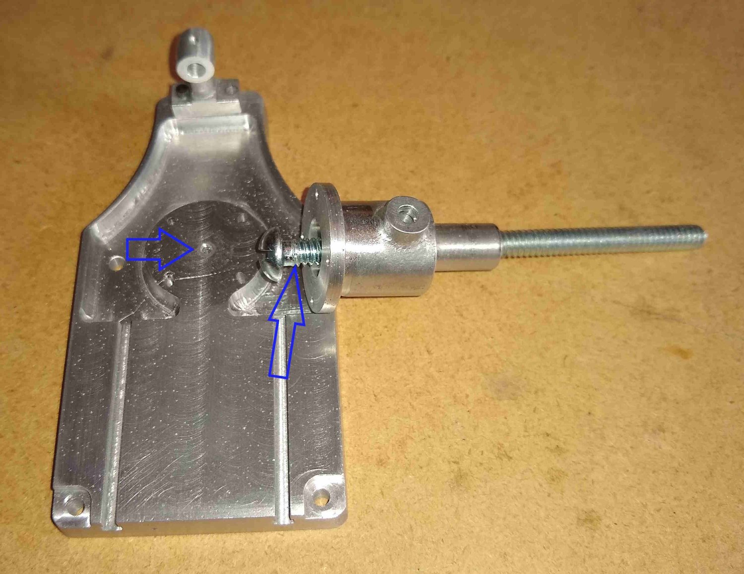
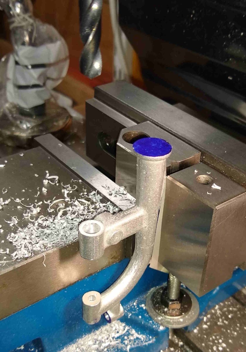
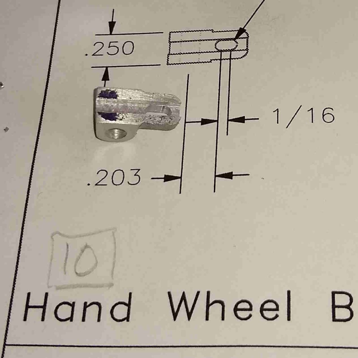
Below, is Pt 10, the small Hand Wheel Bearing Casting that supports one end of the Spindle Feed Shaft. The casting didn't have any square surfaces on it but some careful filing made it square enough to clamp in the mill vice.

Below, test-fitting the screw that holds the Hand Wheel Bearing Casting to the frame.

And checking that the Hand Wheel Bearing Casting is a sliding fit on the elongated pad on the Frame.

I've still to add a square slot in one of the Frame holes to accommodate the Spindle Rack.
The Frame has never left the toolmakers clamp since it was first clamped in there almost two weeks ago. The clamp has done it's job well - I'll have a very careful think before removing the Frame from the clamp when that day comes, but I suspect that it should be fairly easy to re-clamp it back into the same position if I have forgotten to machine some feature on the frame.
All for now,
Richard
-
A short update on the progress over the past week or so.
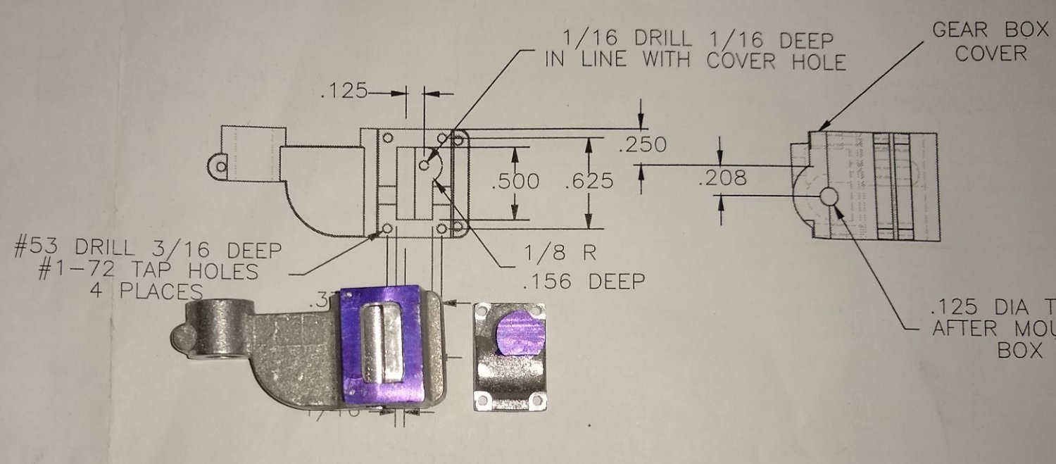
I've still been working on Knee/Gear Box area...ie Pt 3, the Knee, Pt 8 Gearbox Cover and Pts 26 and 27, the two Worm shafts. There was a bit more to it all than I first thought.

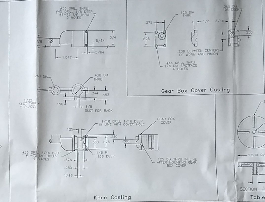
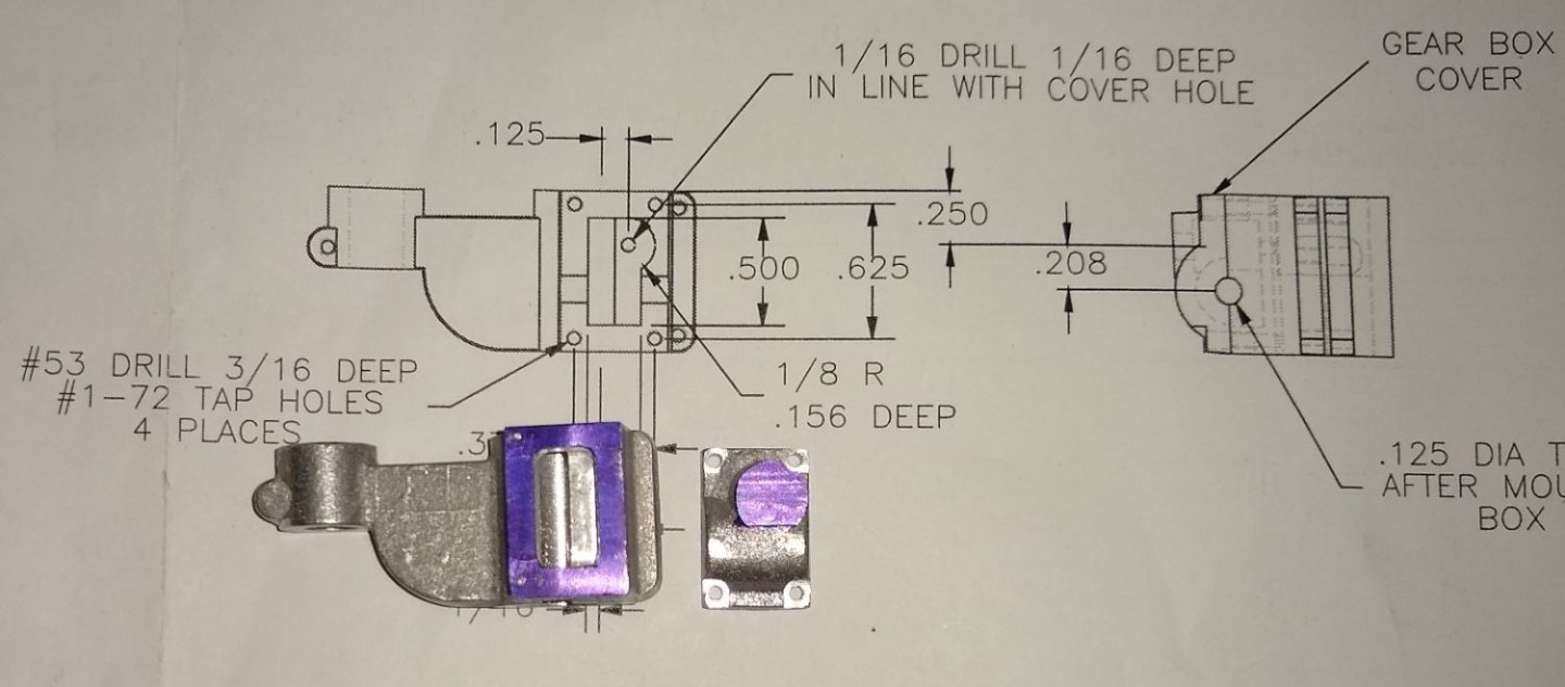
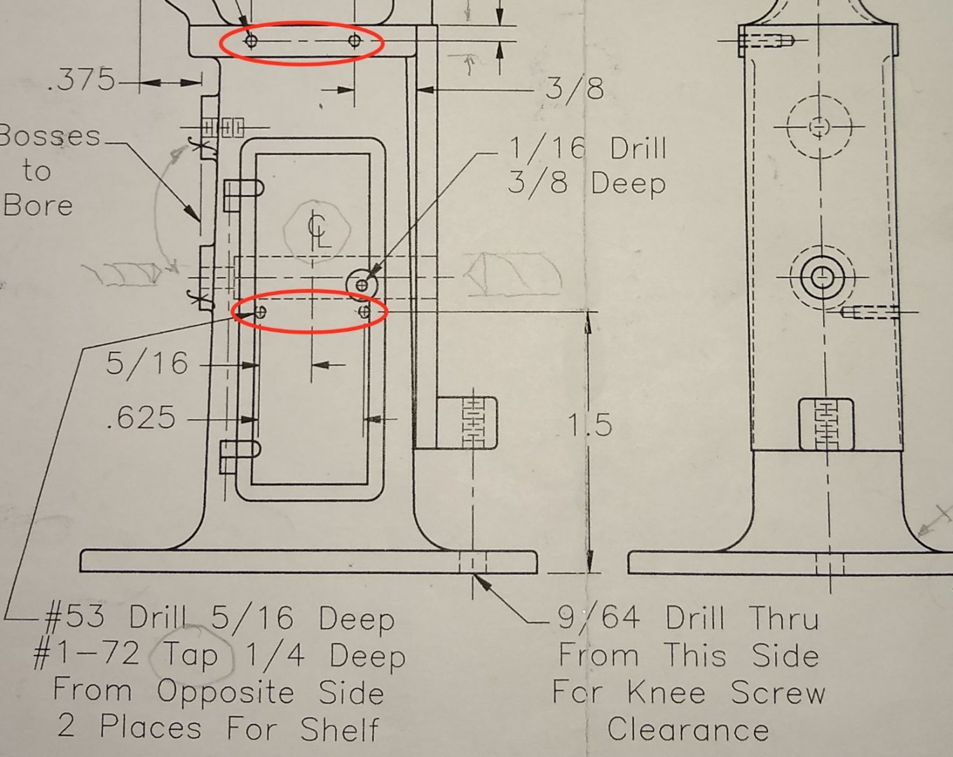
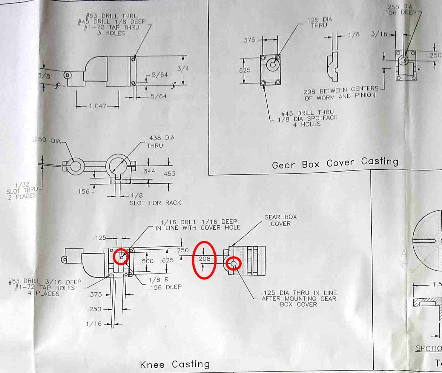
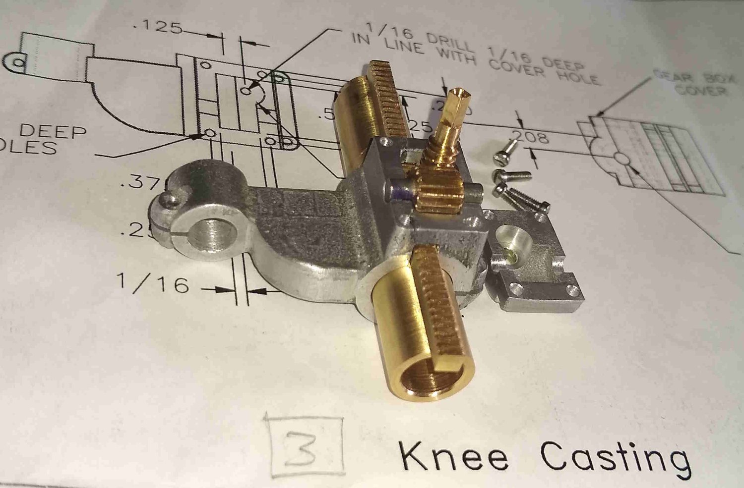
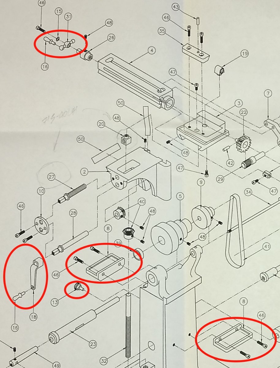
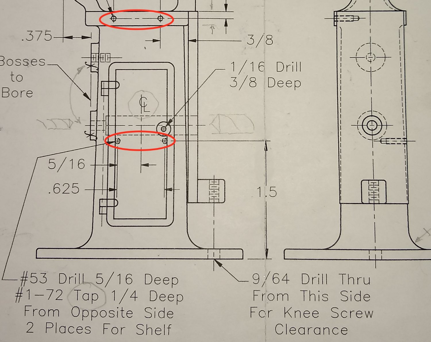
One of the key dimensions is, not surprisingly, the centre distance between the Pinion centre line and the Worm shaft centre line ie dimension 0.208" marked in red below.
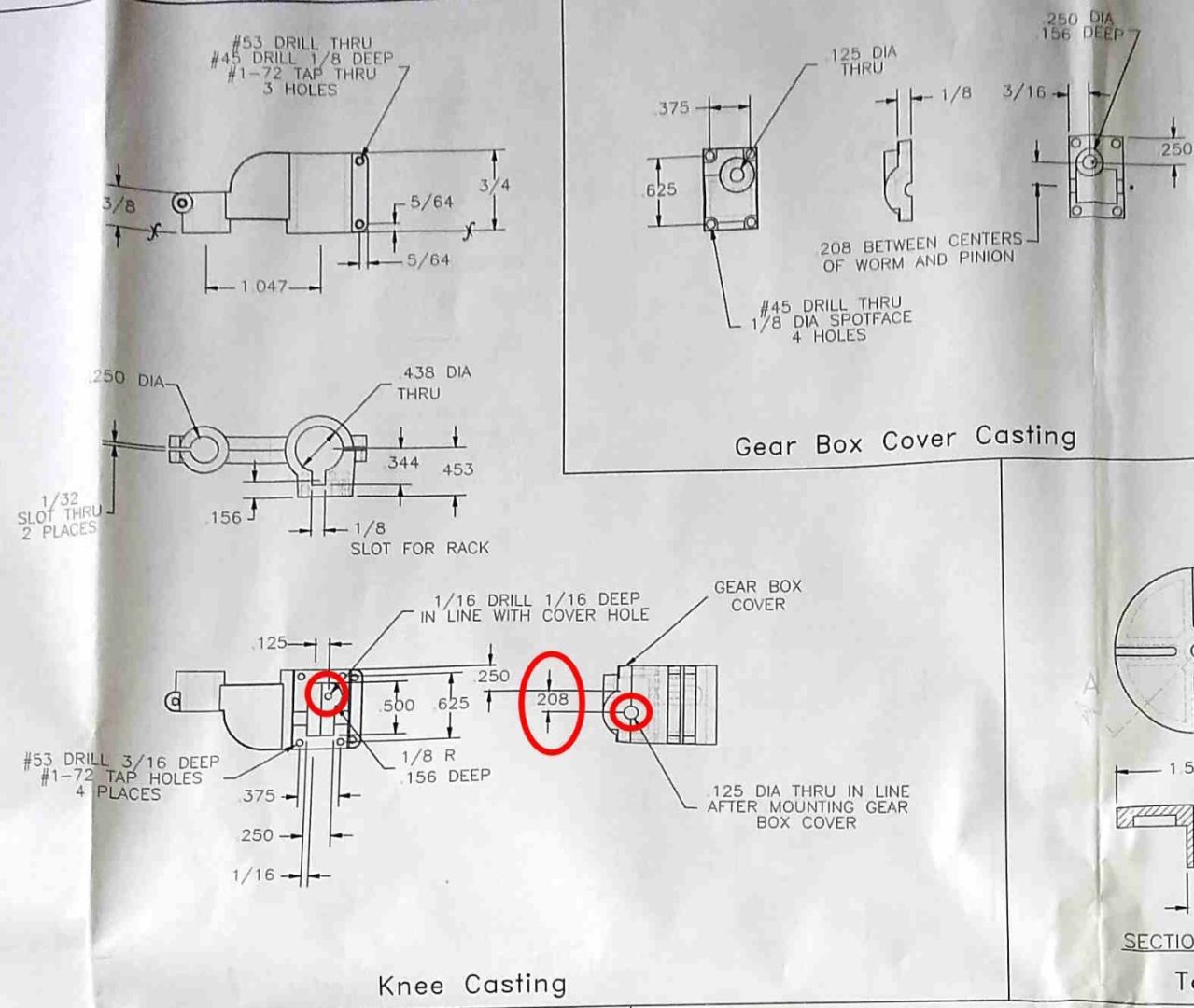
Also, the depth of the square cut Column Rack slot is quite important since it determines the engagement depth between the Worm teeth and the Rack teeth.
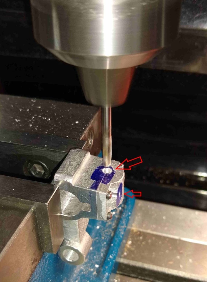
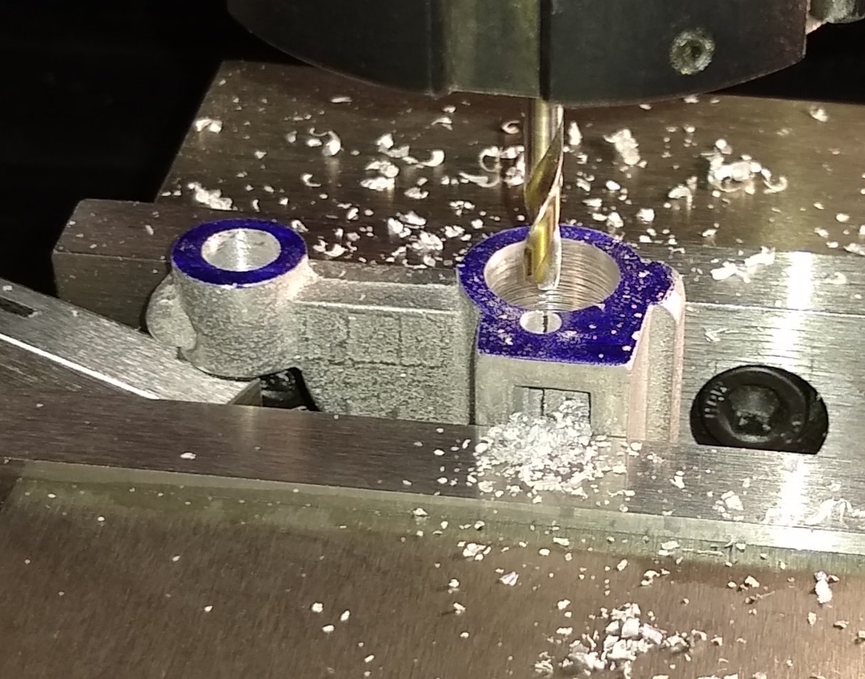
Drilling the Worm and Pinion bearing holes.
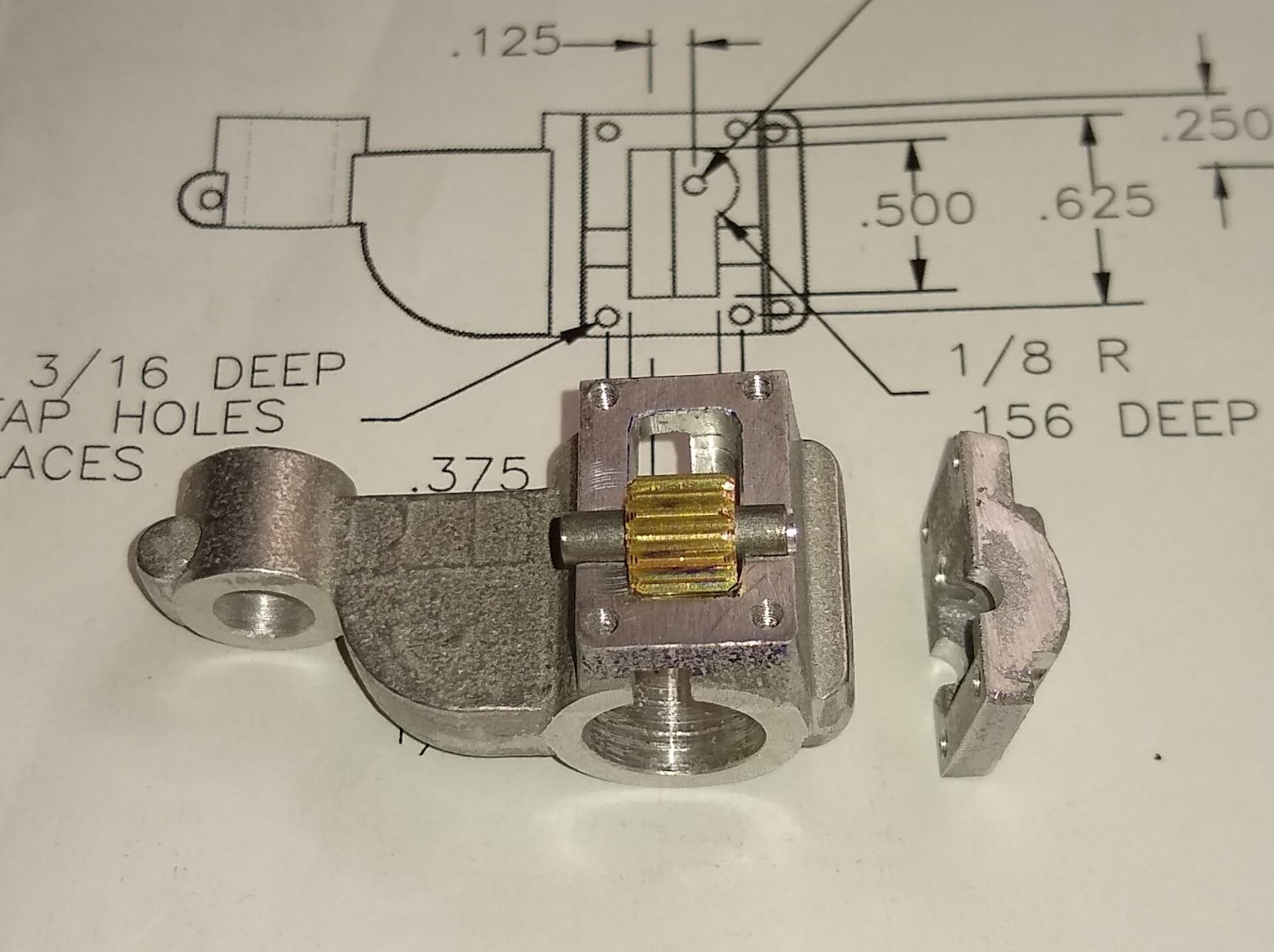
A test fit of the Pinion + shaft into the Knee. I lightly chamfered the Pinion edges to prevent rubbing against the housing walls.

Now preparing the Knee for the 1/32" slots cut at either end. The slots allow the Knee to clamp on the Column and the drilling Table. Firstly drill and tap the holes for the clamping screws.
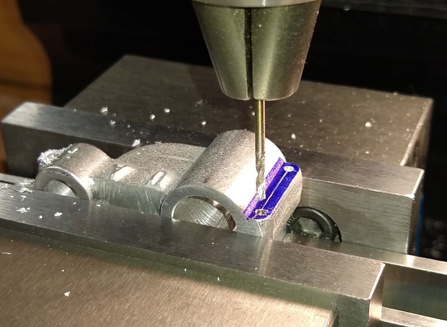
Now using the slitting saw to make the 1/32" slots. I am always very wary about slitting saws for some reason. So two safety shields are used. The slitting went off without incident.

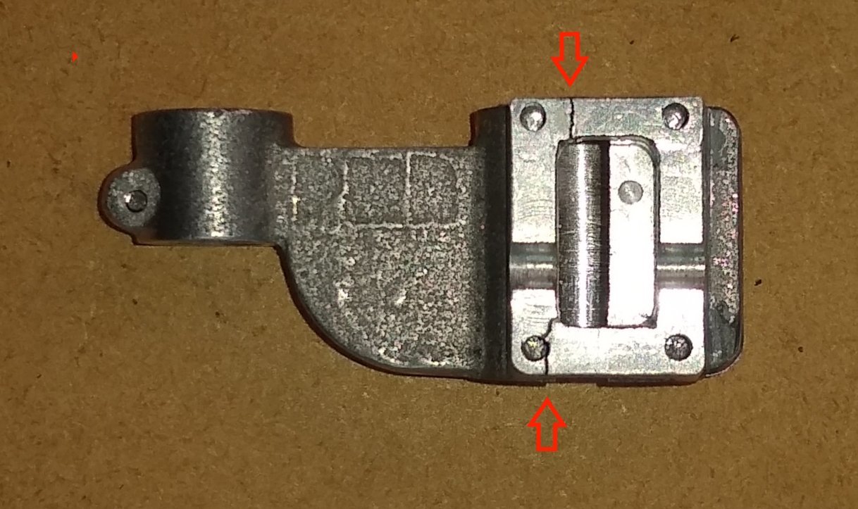
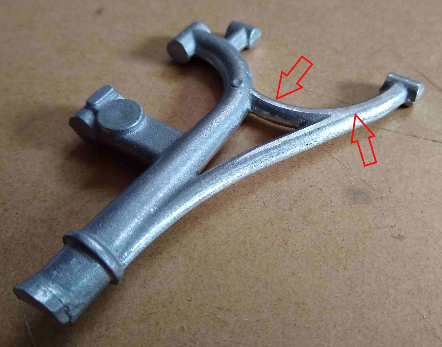
Whoops...one quarter of the Knee clamp snapped off. The crack lines are shown by the red arrows. My fault - I was gently trying to slightly open out the clamp hole but didn't appreciate how little meat there is in the area of the red arrows. After a little think I realised that the Gearbox cover lid (with it's 4x fixing screws) would, in effect, hold the broken quarter firmly in it's final assembled position. So crisis averted.
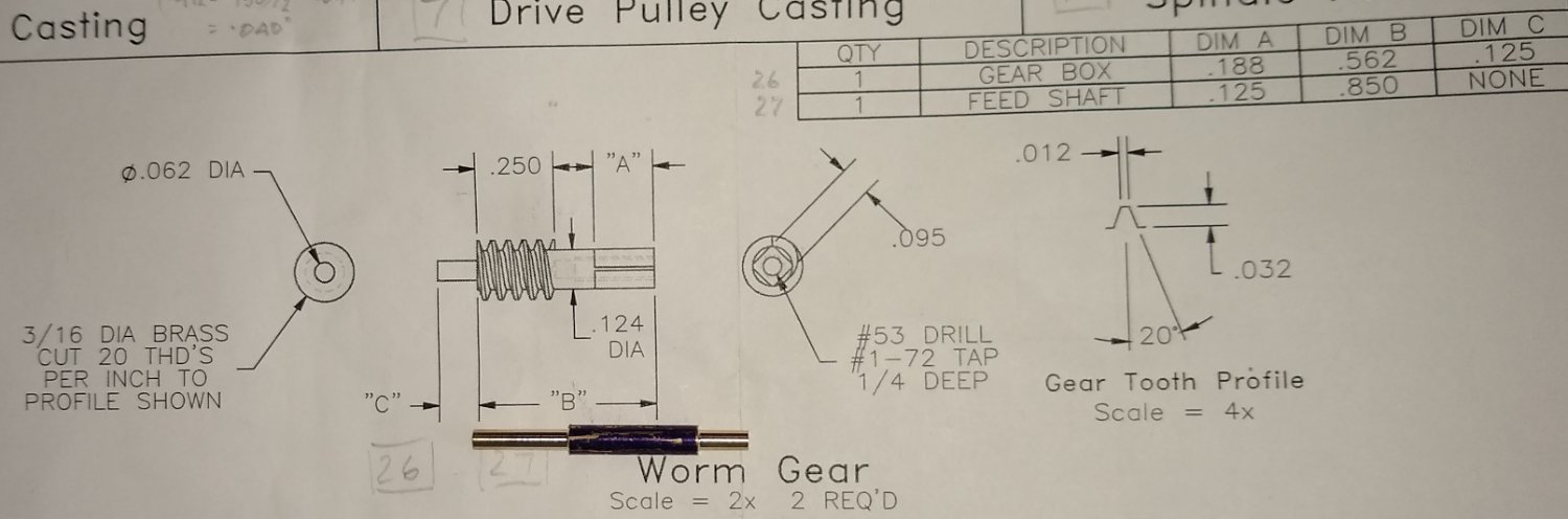
On to the Worm shafts. More single point thread cutting, but this time on brass. I decided to combine the thread cutting operation in to one task ie leave the two worm shafts as one piece till the thread cutting was complete, and then separate them. This worked fine.
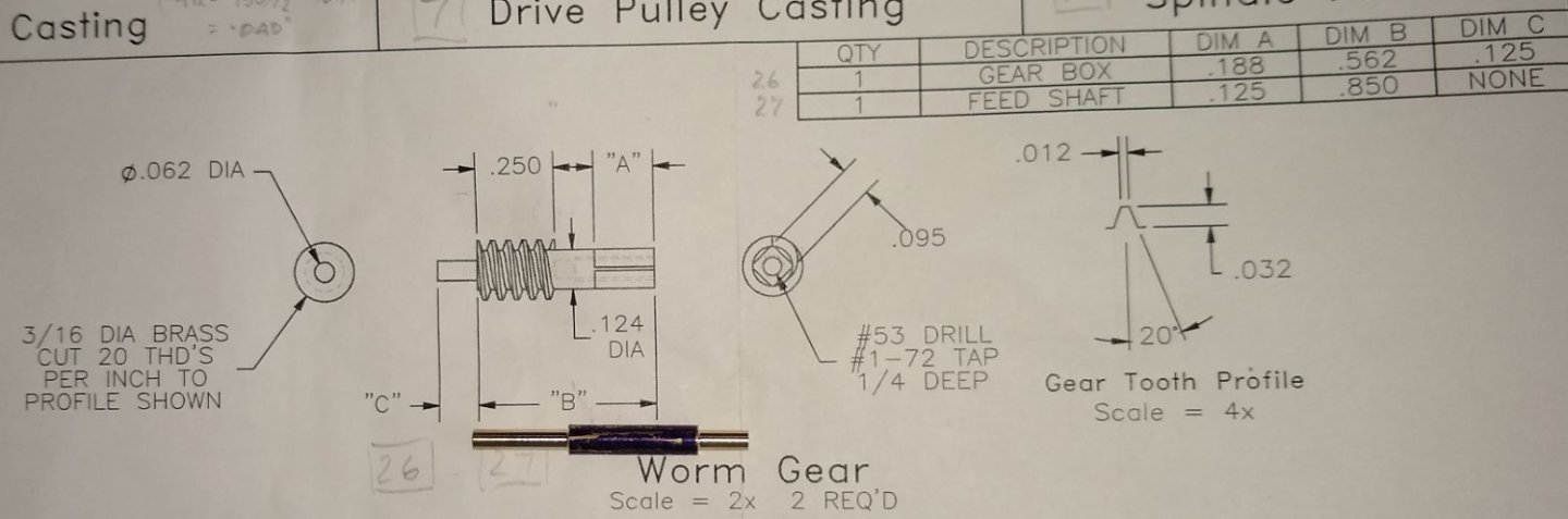
Below, the HSS tool sharpened to 40 deg.

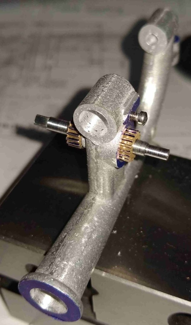
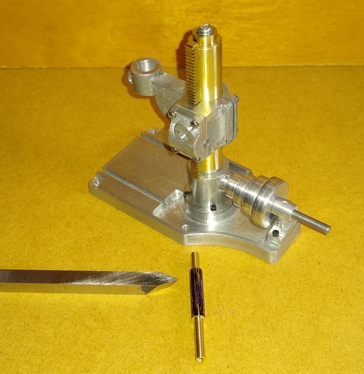
Gearbox parts ready for assembly.

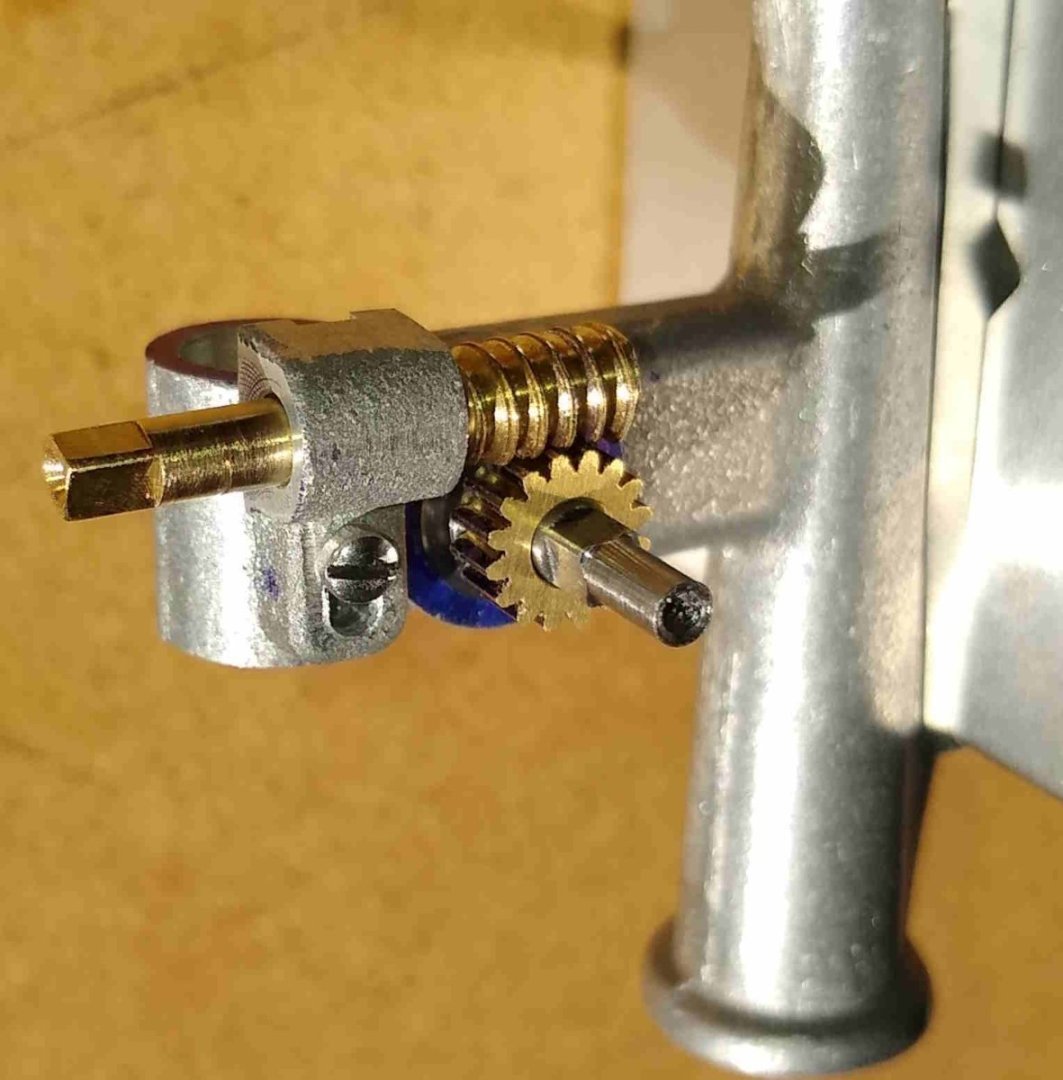
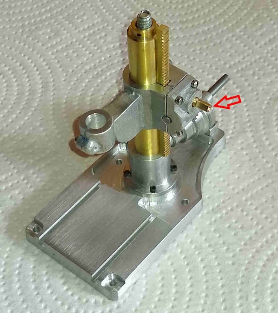
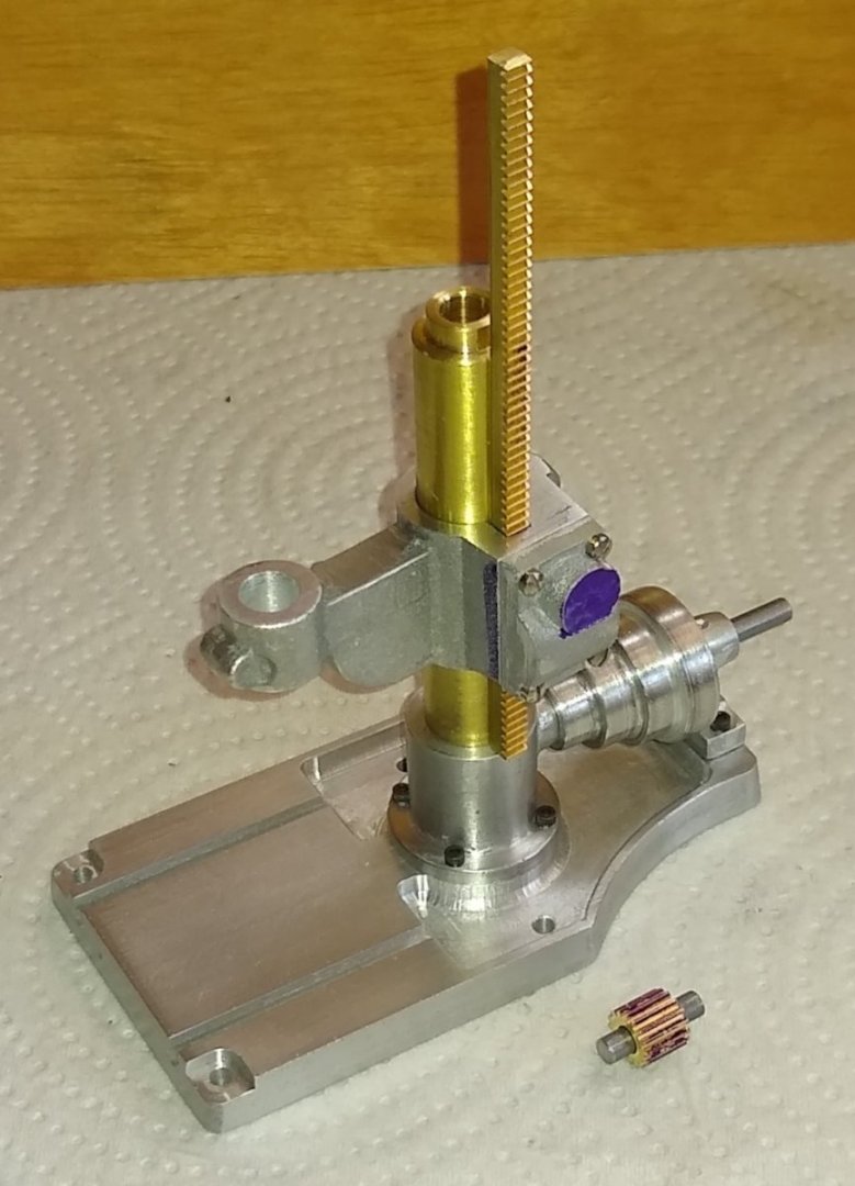
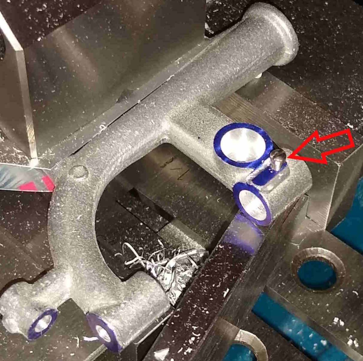
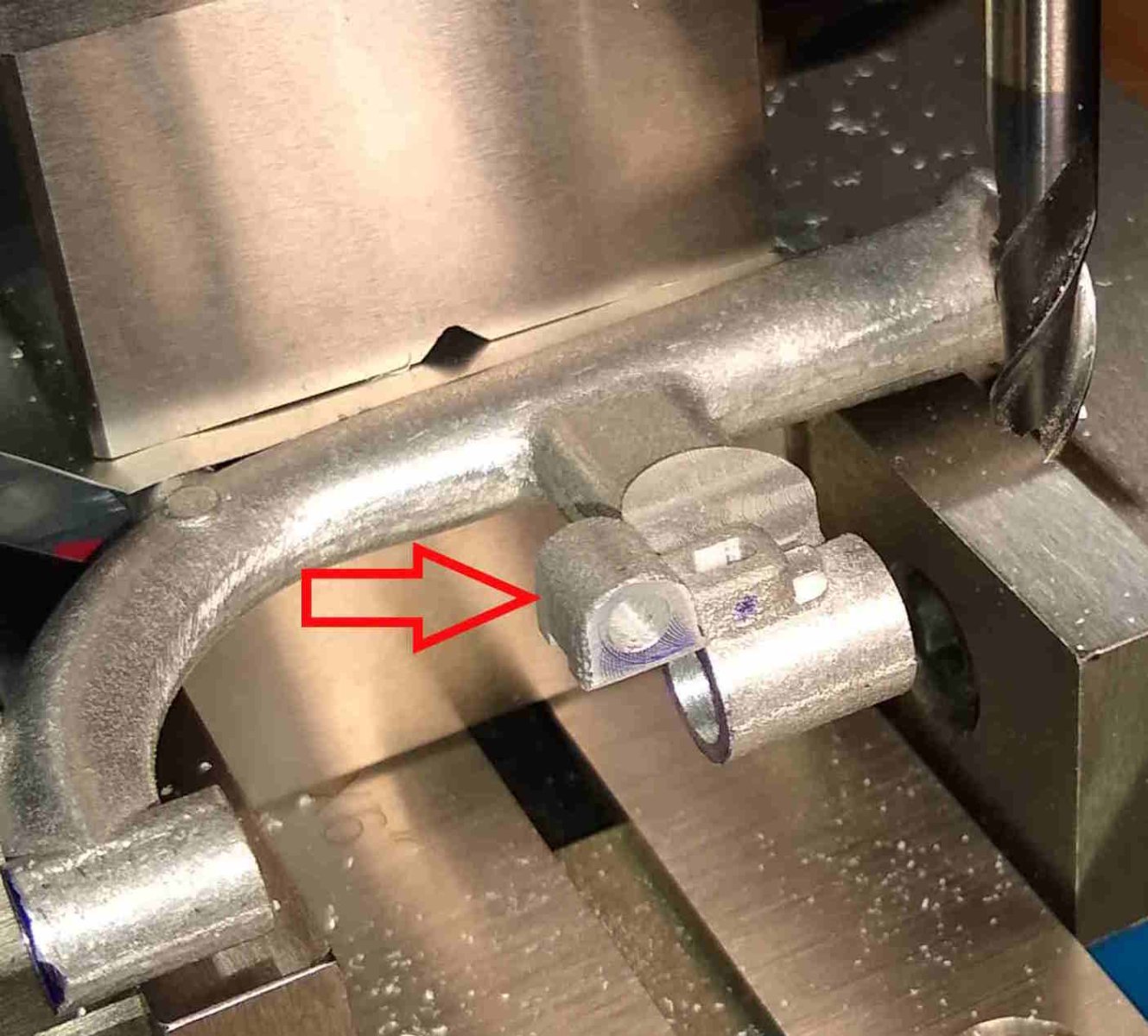
Finally, the assembled Knee and it's gearbox. The shaft's square drive (red arrow) rotates reasonably freely apart from a slight tight spot at about 2 o'clock. Some further fettling require.
It's been 30 degrees Centigrade in the shed for the past week or so - we're getting an Indian summer in Scotland. Lovely as it is, it makes concentration slightly more difficult. 30C isn't that hot in the grand scheme of things but one needs a couple of weeks to build up a tolerance for it. And by the time you do it's back down to 12C-15C 🙂
All for now,
Richard

- mtaylor, king derelict, Egilman and 3 others
-
6
-
WoodButcher,
I hope you don't mind but I thought this might be of interest.
Iain Tyrrell has visited the Italian location of the Riva powerboats ... Riva Aquarama Lamborghini - Tuning the Most Beautiful Boat in the World | Tyrrell's Classic Workshop -
Lots of interesting details discussed. A gorgeous boat.
Richard
-
Hi all,
A quick update on the this week's progress on the PM Research Drilling Press Machine.
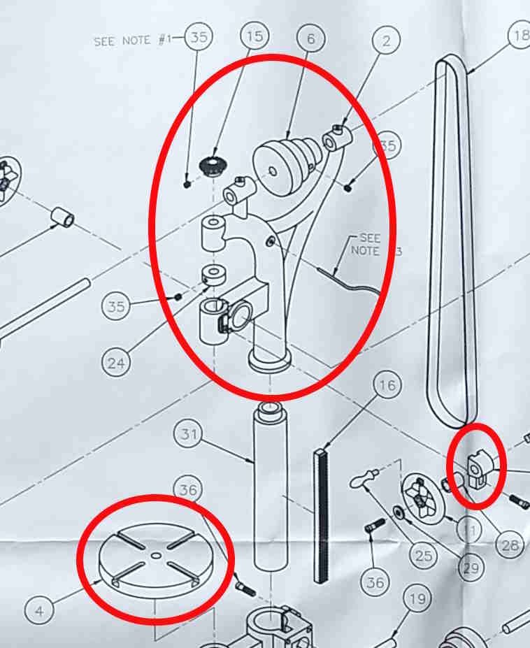
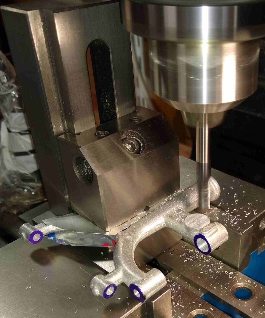
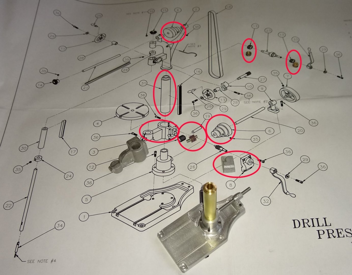
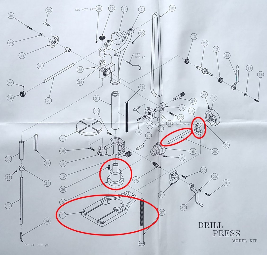
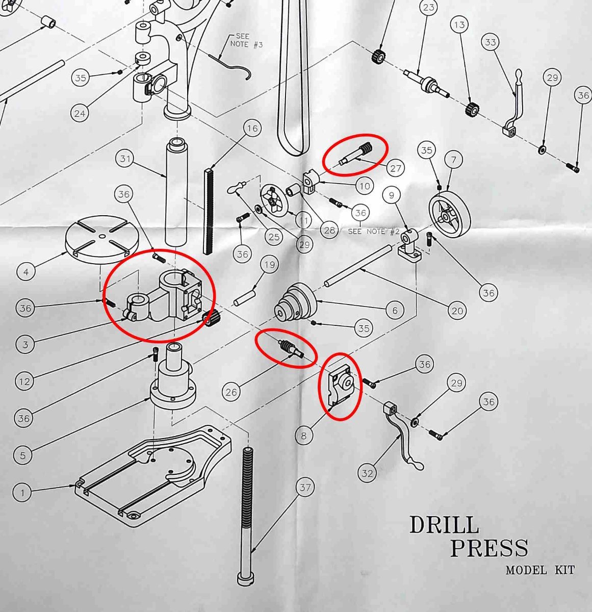
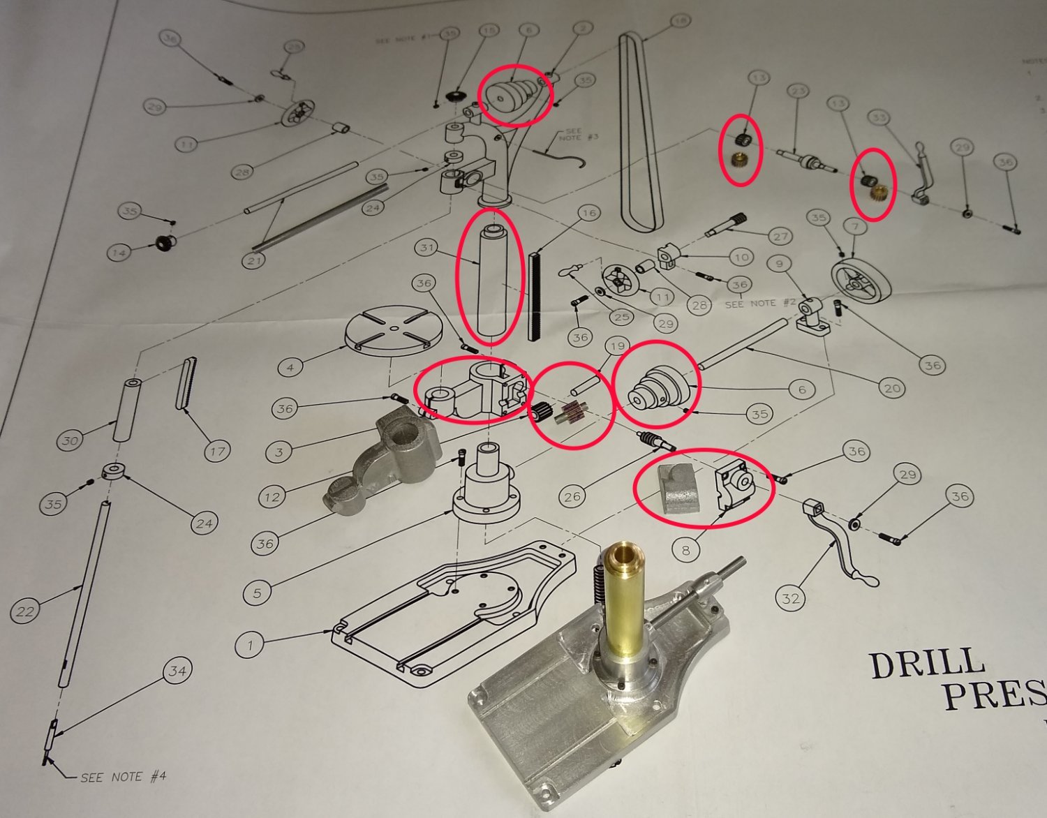
Below are most of the parts tackled in this post, circled in red
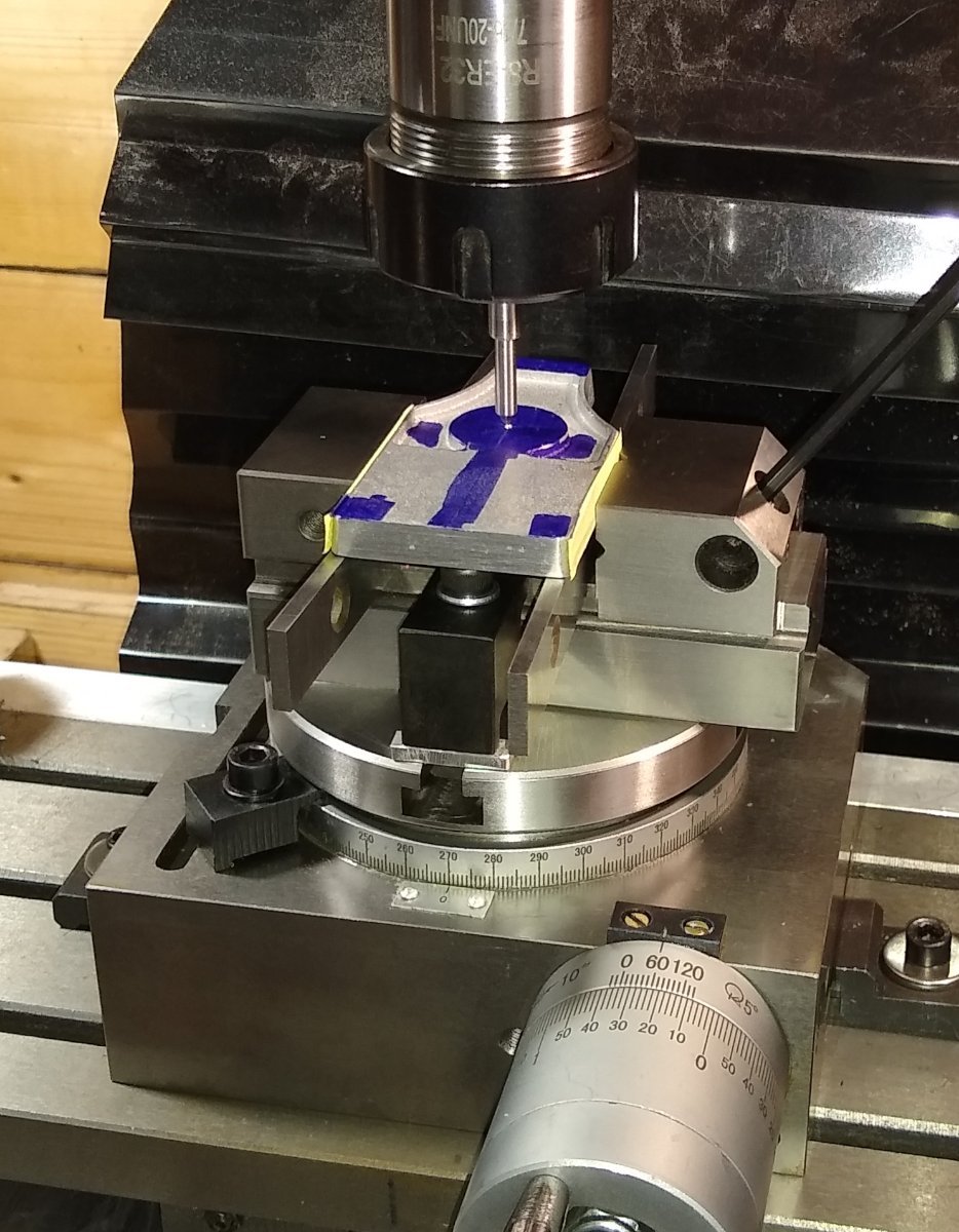
Below. The Knee, Pt 3 is quite complex, and in many ways similar to the Knee of the Milling Machine that I completed recently. The Knee houses a Gear Box that encloses a Worm - Pt 26 and a Gear - Pt 12, which drives the Column Rack - Pt 16, up and down. As usual, reasonably tight machining tolerances are called out to make sure these parts interface correctly. The Gear Box Cover is shown top right in the drawing below.
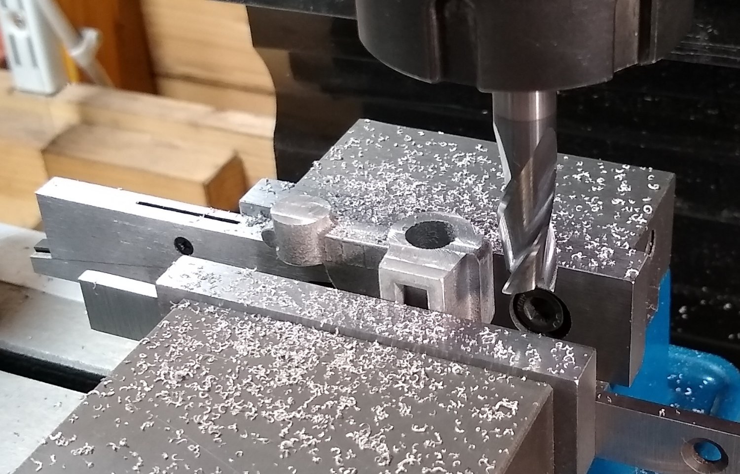
Cleaning up the Knee faces to get the show on the road. Followed up by drilling out the two holes.

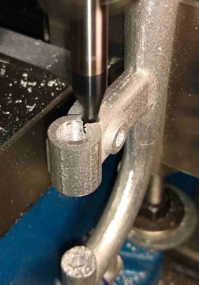
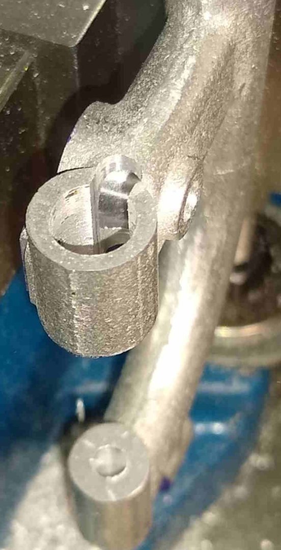
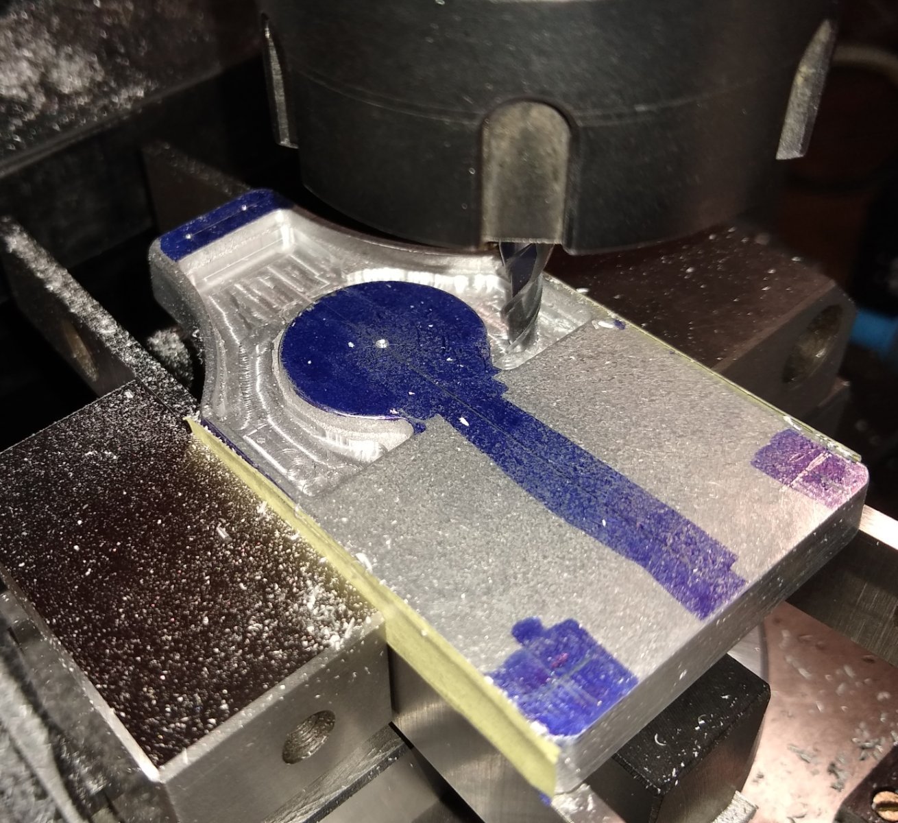
To accommodate the Rack a square groove needs to be added to the 0.438 diameter hole (which the Column slides in to). The groove penetrates through to the rectangular recess (facing the camera). I don't have a broaching set so decided to drill out as much groove material as possible before using my trusty square needle file to finish off the groove.
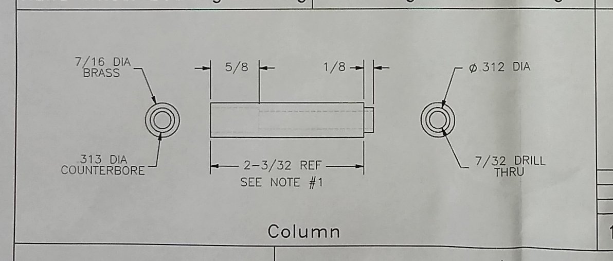
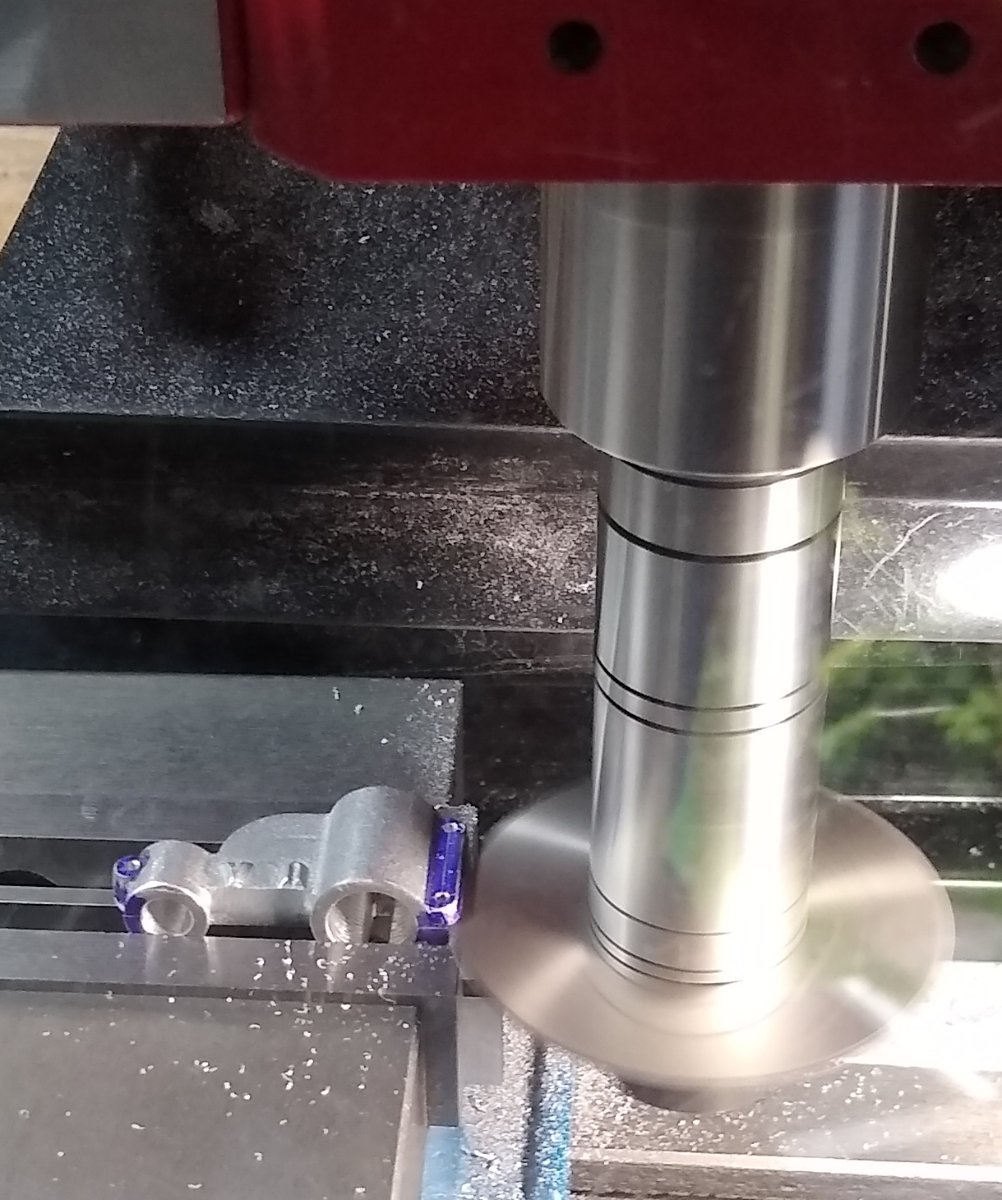
Below, a quick look at the brass Column drawing. It was straightforward to make on the lathe.
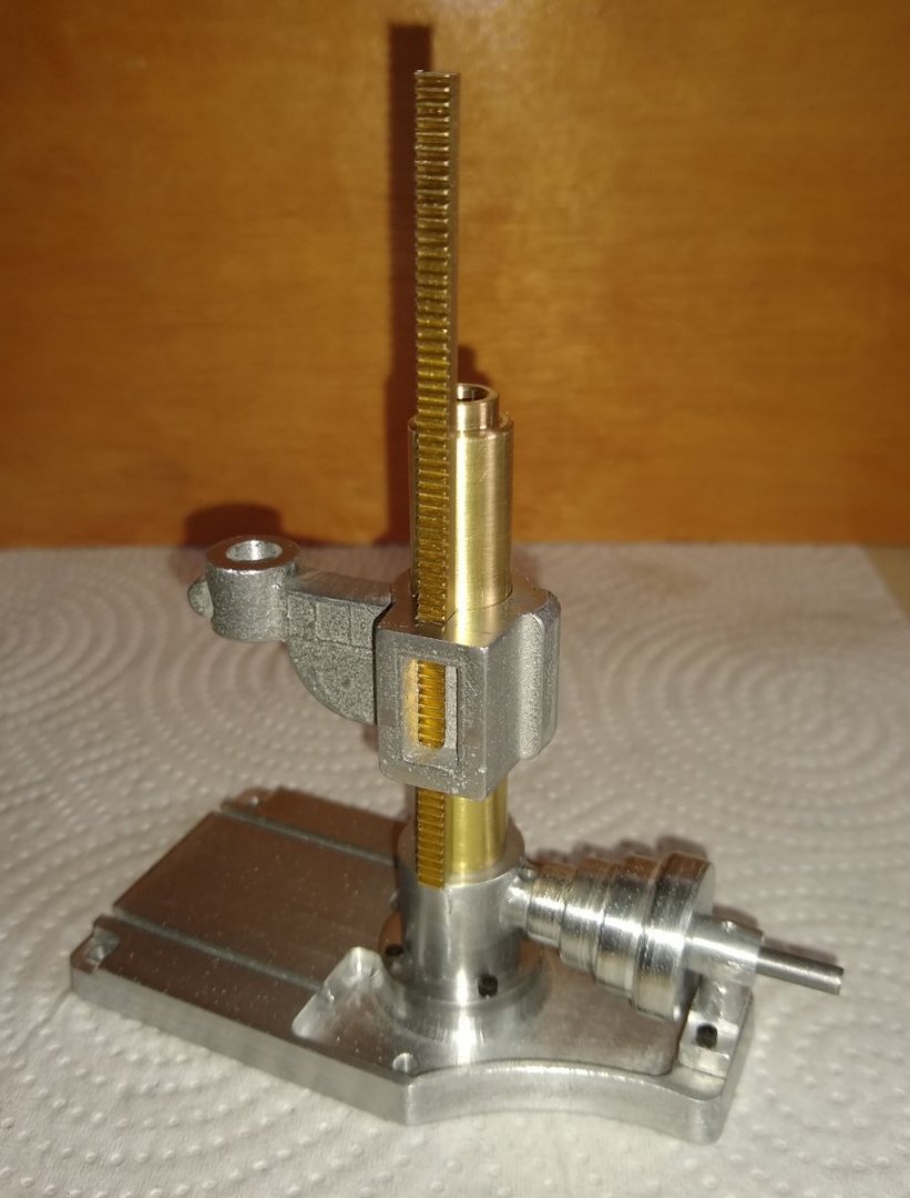
And a sub-assembly showing the parts fitted together. I later noticed that I needed to take about 0.040" off the base of the rectangular recess. That would allow the Rack teeth to protrude sufficiently in to the rectangular recess and so mesh with the Gear
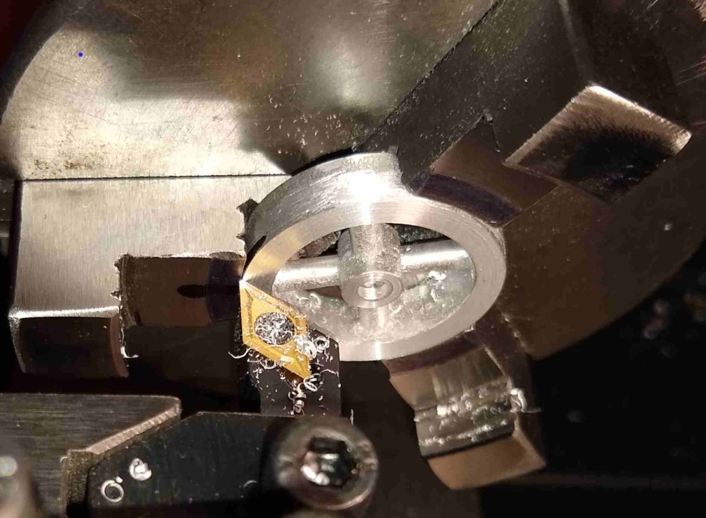
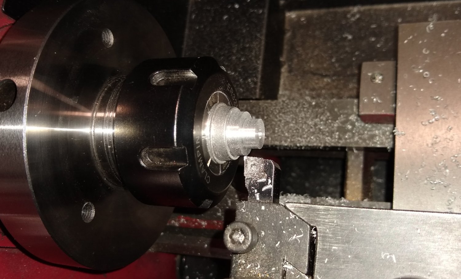
I had also made two identical Pulleys (one shown above) plus their Shafts.
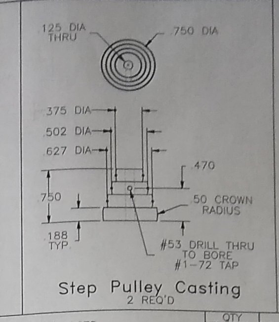
When I previously made the Milling Machine pulleys they had a 1/4" diameter hole through them which allowed me to use a 1/4" mandrel for turning the stepped diameters. But the Drill Press pulleys only have a 1/8" hole (and shaft) which I felt was too weak to do any turning on. So I gingerly cleaned up the largest diameter to fit into a 20mm collet and then turned to size the other stepped diameters. Yes, the largest diameter only sits about 4 or 5mm deep into the 20mm collet but I felt it had a strong enough grip, especially for turning Aluminium.

Back to the Knee. Now it was time to fit the Gearbox Cover. This entailed drilling and tapping 4x mounting holes. The Cover casting was just on size so little cleaning up was possible, The #1-72 holes seemed very close to the edge of the casting, so I moved them slightly inboard. I also needed to spot face the Cover in four position to clear the screw heads.
After much faffing about I felt it was best to clamp the Cover to the Knee and drill the fixing holes. I used a 1.5mm (tapping size) drill, later opening out the Cover holes to clear the screws.
Finally, the current sub-assembly of parts. The Knee still has a lot more work to be done on it. The Gear is shown sitting next to the Base - this will fit inside the Gearbox.
That's all for now, back soon 🙂
Richard
- Egilman, king derelict, Canute and 2 others
-
5
-
Thanks Mark.
Even after only a few weeks away from my workshop I start to get withdrawl symptons. I think I just need to be making things... it's probably the Dopamine release from achieving milestones in a project, and having something to concentrate on. Maybe that's what model making is all about 🙂
Anyway, hope you have a comfy chair and a decent supply of beverages.
See you again shortly,
Richard
- Egilman, king derelict, GrandpaPhil and 3 others
-
6
-
Seems Russia has around ten thousand rusty old tanks sitting in fields. But refubishing them to usable condition is much quicker than producing new tanks... https://www.popularmechanics.com/military/weapons/a44536878/rebuilding-russian-tanks/
" This upgrade process turns broken-down clunkers into modern fighting vehicles. It is far cheaper, quicker, and simpler than making new tanks from scratch. In theory, each plant is capable of producing roughly 20 modernized tanks per month, boosting Russia’s replacement capacity from 20 vehicles a month from UVZ to more like 120. "
Richard
- Haliburton, Canute, Old Collingwood and 2 others
-
5
-
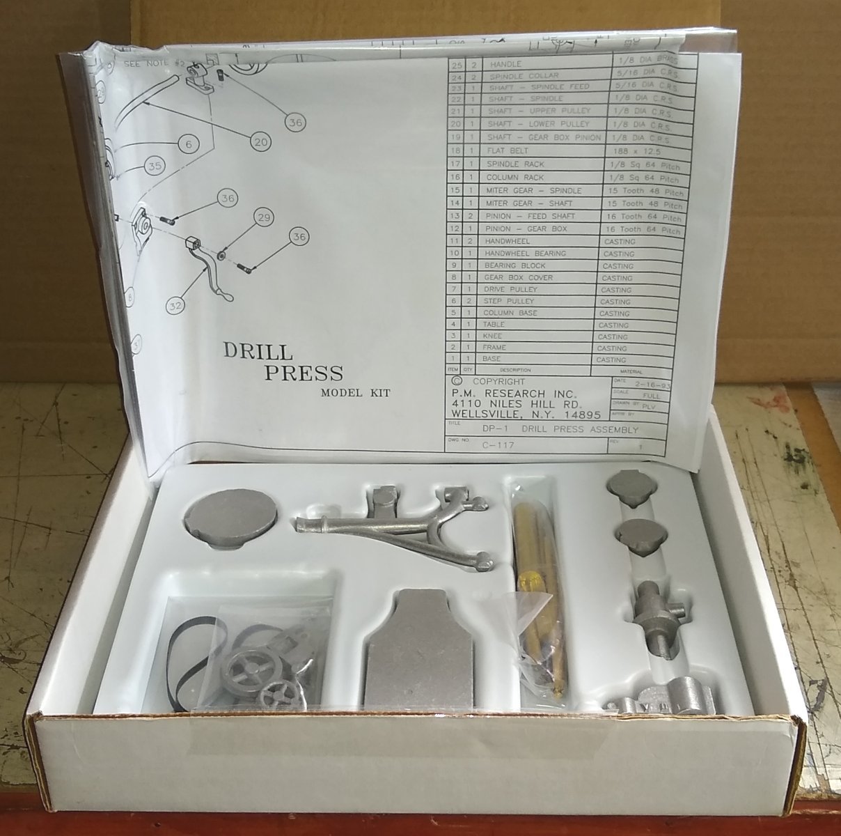
For my Autumn project I have gone with PM Research's Drill Press Kit .... https://pmmodelengines.com/drill-press-kit/
I sourced it in the UK via https://www.forest-classics.co.uk/pm-research/pm-machines/pm-research-drill-press in the Forest of Dean.
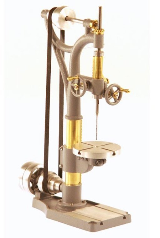
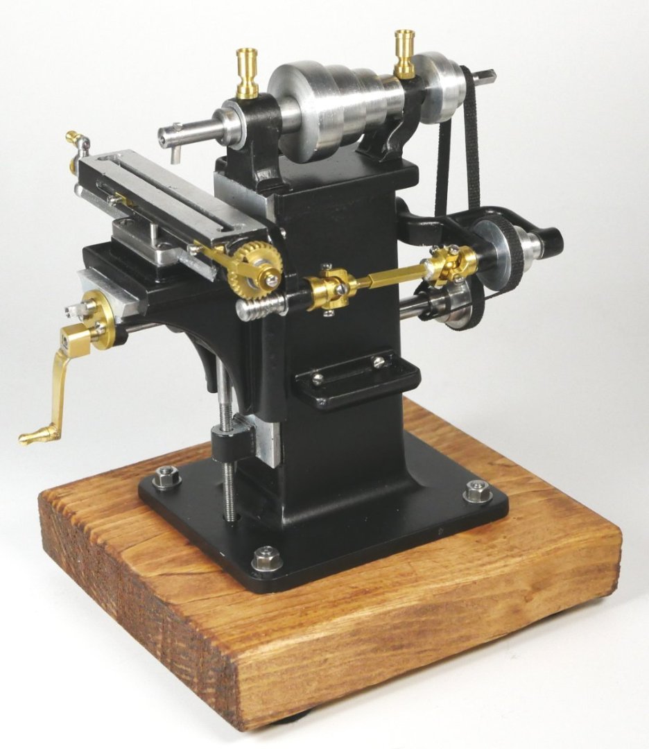
Below is a PM Research image of the finished drill. It is based on a J.E. Snyder (Worcester, Massachusetts) upright drill press. The original item stood 98" (2.5m) tall and weighed 800 Lbs (364 Kg). More here ... http://vintagemachinery.org/mfgindex/imagedetail.aspx?id=3067
A quick look at the box contents....two drawing sheets and all the Aluminium castings, stock metals and fixings needed to finish the model.

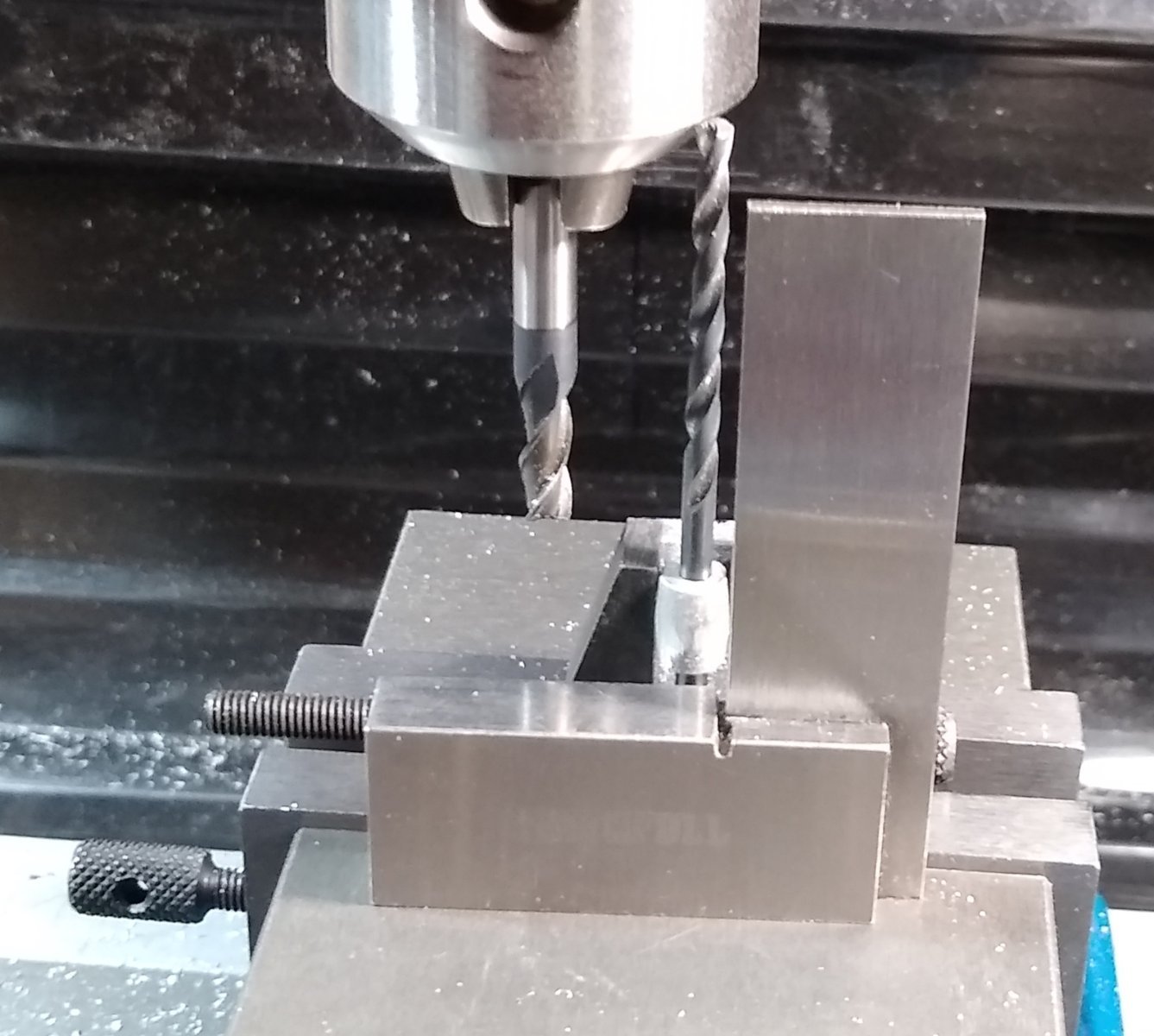
Below, all the parts. I decided to start from the bottom and work upwards, so for this Post - Pt 1- the Base, Pt 5 - the Column Base, Pt 9 - the Bearing Block and Pt 20- the Lower Pulley Shaft.
I watched Part 1 of Joe Pie's excellent build of the drill ....https://www.youtube.com/watch?v=voeBhlRVBi0 That gave me a lot of starter tips. But have yet to watch the other episodes since I wanted initially to try to do my own thing....I suspect I will be back looking at Joe's videos before long though 😉
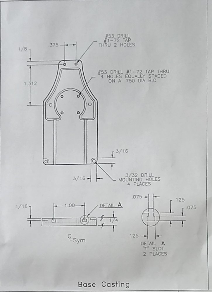
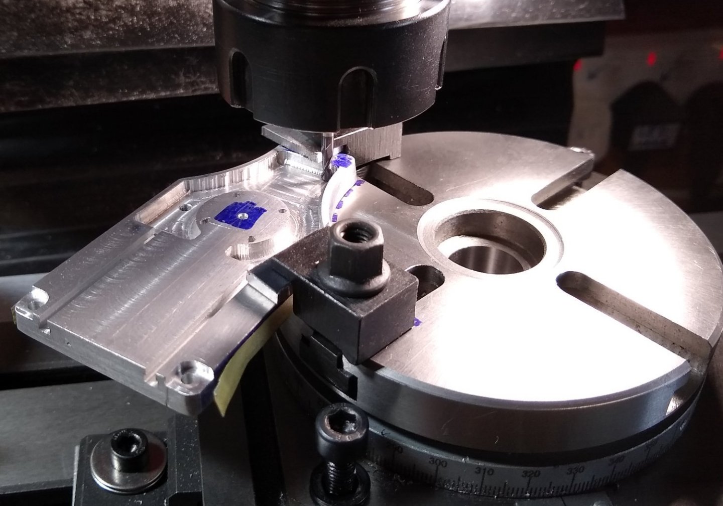
So, to the Base. Quite a lot of machining required including the use of a Rotary Table.
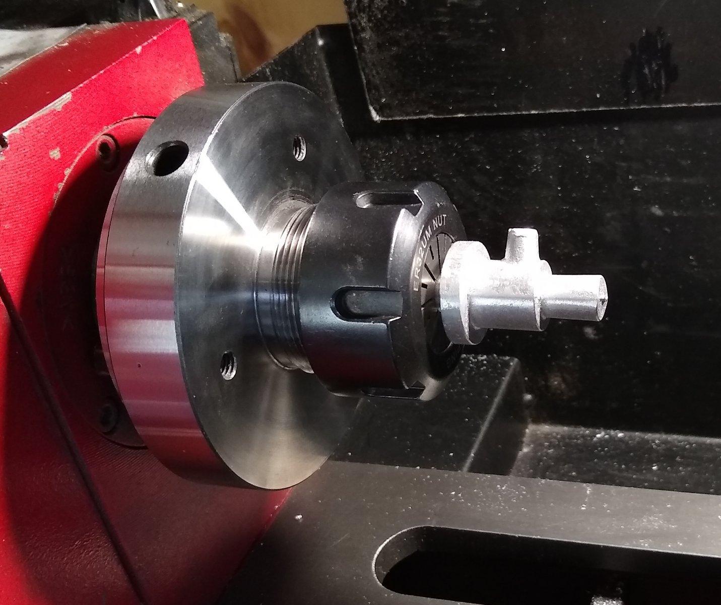
Below, centring the 4" Rotary Table (RT) with the quill of the milling machine.
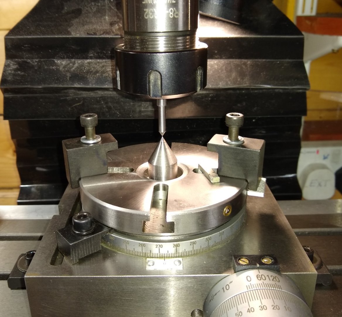
Next I needed to mount the Base casting on the RT with the Base's circular pad coaxial with the quill. I measured the pad diameter - for a casting it was quite circular but a bit undersize compared to Part 5 which would sit on it . I turned an 'alignment jig' that matched the pad's diameter on one end, with the other end fitting in to a 20mm diameter collet. I then lined up the pad and the jig by eye and finger touch.
Below, the Base now clamped in a toolmaker's vice and fitted to the RT. I also marked the centre of the pad with a sharp point since I felt that might come in useful later on. Everything fitted onto the 4" RT, but it was a little tight.

Now reducing the thickness of the hollowed part of the casting to allow the T-Slots to emerge cleanly in to that space. IIRC, I used a 5mm 3 flute end mill.

Now the fun stuff. I had skimmed the inside straight edges of the hollow with a 3mm round nose end mill...now it was the turn of the pad. It actually worked quite well, but by the time I was finished the pad's diameter was now quite a bit less than of Part 5 - the Column Base. I saw remedial work fast approaching over the horizon - see later.
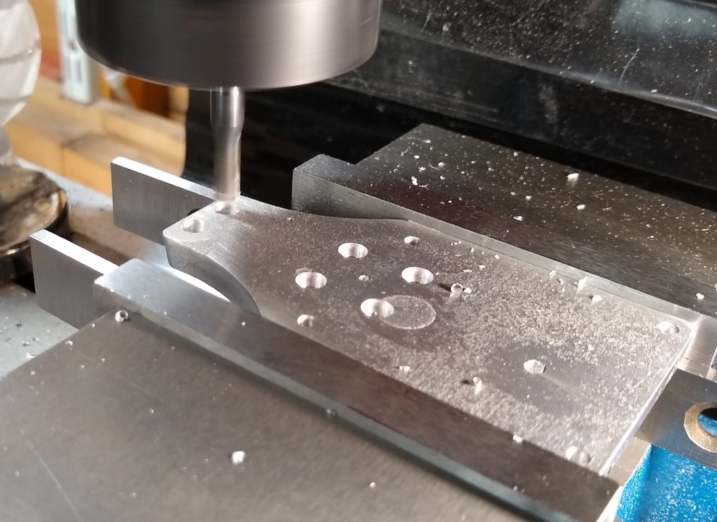
Below. Now to drill and tap the the four #1-72 holes in the pad. That didn't go well. The pad's diameter was already on the small side ie getting a bit tight for #1-72 screws, so I decided to use a #0-80 tap (- I already had suitable 0-80 screws at hand).
The tapping did not go well. The Base casting is appx 0.300" thick, to later be reduced to 0.250" thick...the very small tap broke in the Aluminium casting before it was halfway through the first hole...I don't think it was excessive torque that did it, more likely a slight sideways force. The only way I could get the broken tap out was to grind an old small drill to the tap diameter and hammer it out (wearing safety glasses). That worked but left a large'ish hole. So I went to Plan B - drill clearance holes through the Base and Column for #1-72 screws and use half nuts under the base.

Counter bores being made for the half-nuts.
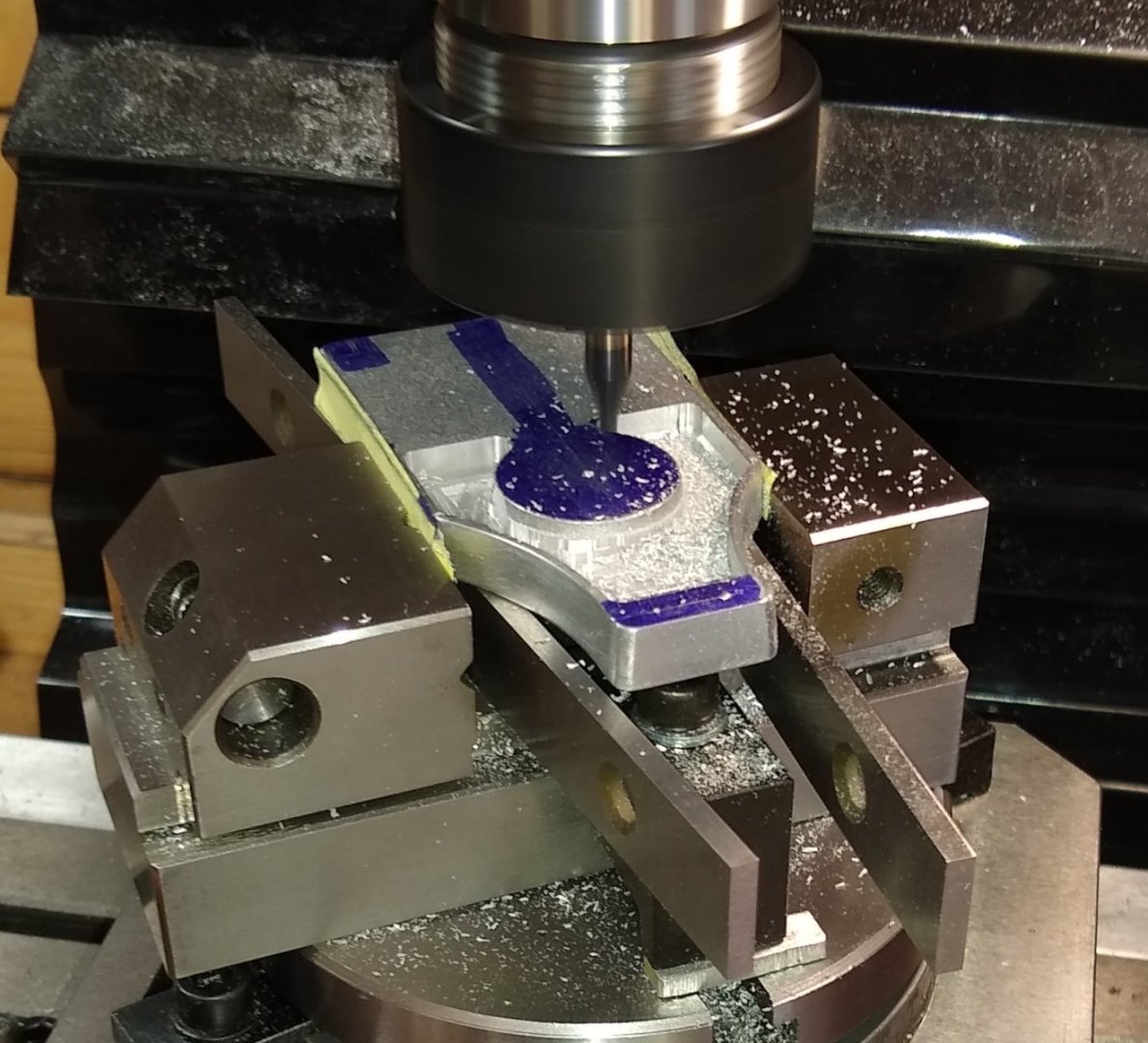
Now making the two T-Slots. Many shallow cuts of about 0.005" using a 2mm end mill were required but it all went OK. I then used a T-Slot cutter to finish off the slots - it only took one (very slow) pass for each slot.

Now to clean up the curved inside faces of the Base using the 3mm round nose end mill. I used the two clamps that come supplied with the RT to hold the Base in place. A smooth 3mm rod in the collet was gently run along the outside of the curved face to align (by eye) the centre of that curve with the centre of the RT. That all worked fine. Note: on the left of the pic the two finished T-Slots are seen.
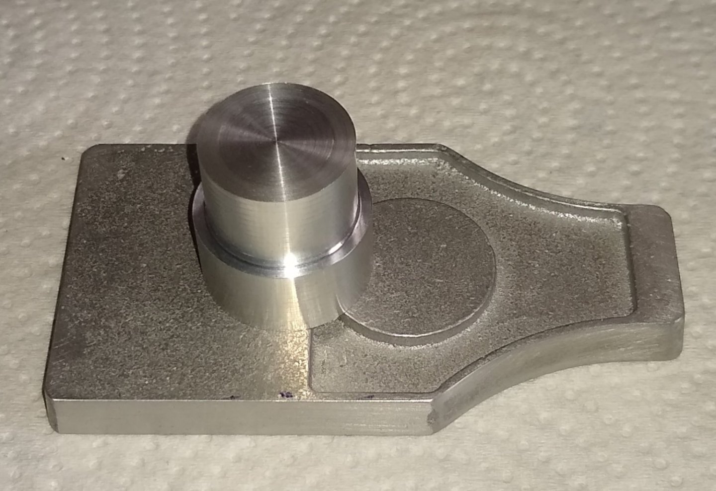
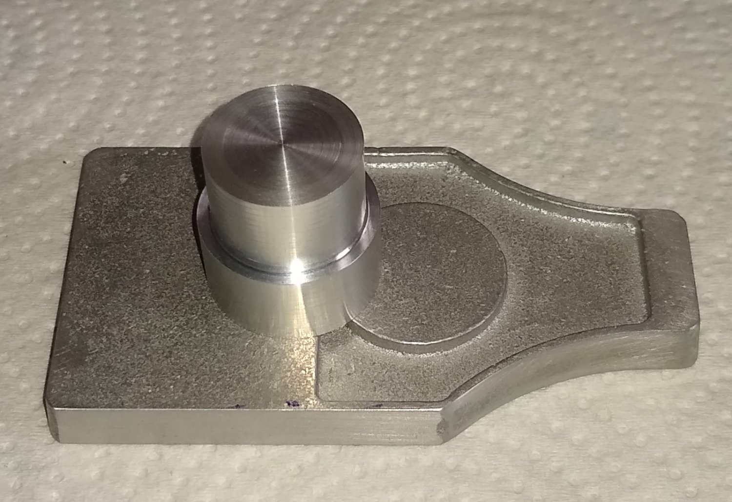
Next, Pt 5 - the Column Base. The casting comes with a circular sprue on the RH end which facilitates chuck holding as seen in the 2nd pic below.
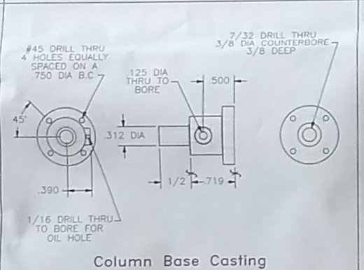
Cleaning up the larger and smaller diameters. The largest diameter should match that of the Base's circular pad, but that pad was now reduced in diameter, so that meant the Column Base diameter also had to be reduced (from what the drawing stated) to match the pad. This had the knock-on effect of moving the PCD of the 4x fixing screws inwards. The protuberance is a bearing point for a shaft - the material around it was cleaned up using Needle files and Emery cloth.
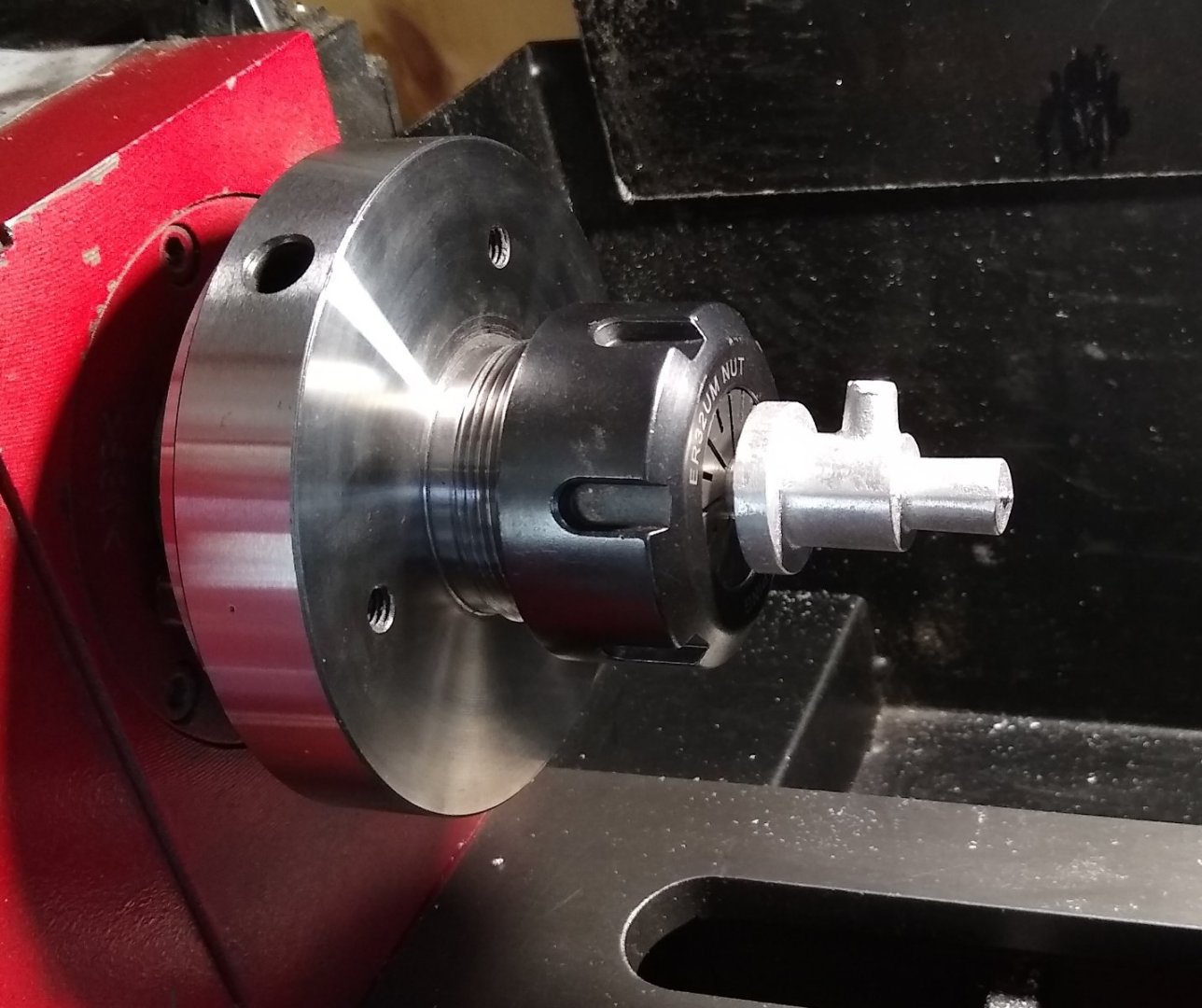
Drilling the 1/8" hole for the shaft, Pt 20. If the part was made of Mild Steel I'd probably have used a more sturdy clamping arrangement.
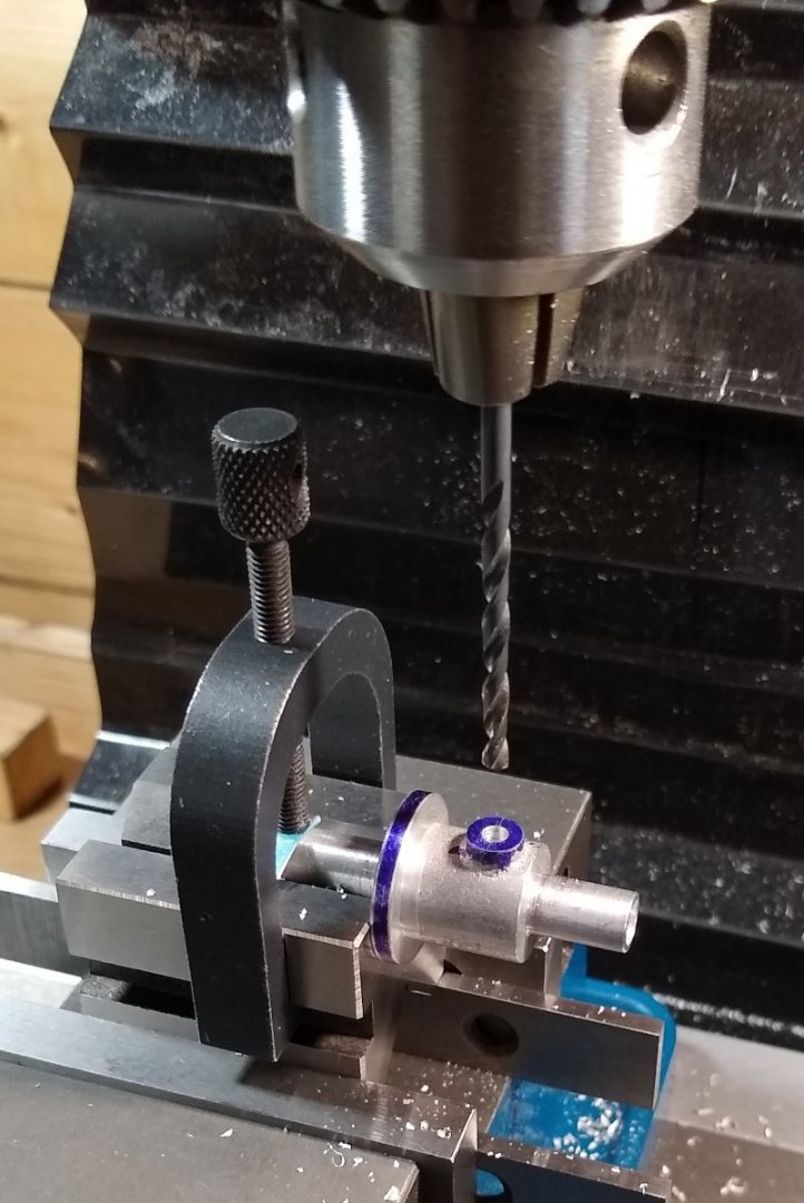
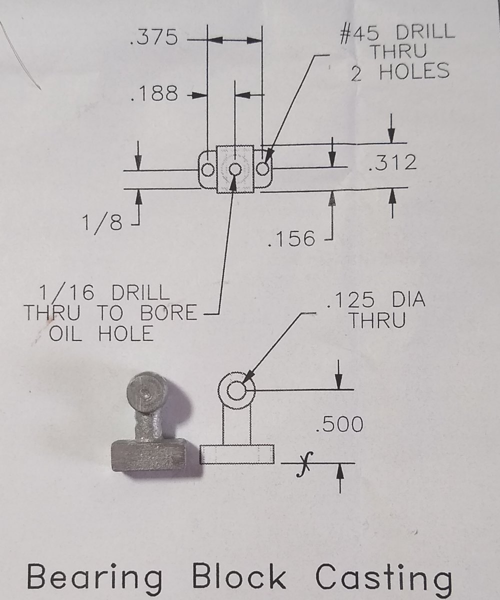
Next, Pt 9 - the Bearing Block. The casting was a little askew, so I trod carefully when machining it trying to make it look as 'square' as possible.
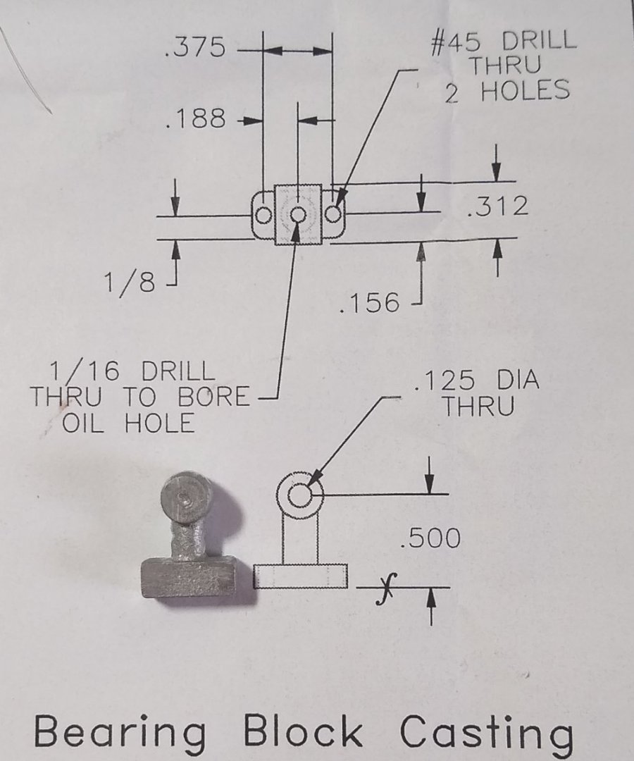
Using a 2mm Stub drill to start off the hole for the 1/8" drill. It had taken me a little while to figure out how to hold the Block but a Toolmaker's Clamp eventually came to the rescue.

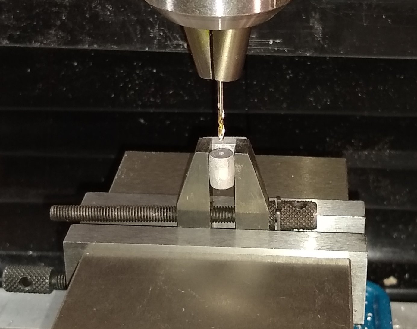
Whilst clamped, I took the opportunity to clean up the Block sides. I didn't go right up to the clamp when milling so that left a small ridge which was later removed with a Needle file.
Turning the Block over to clean up the other side, using the 1/8" drill and a set square for alignment.

Finally, a sub-assembly pic of the four parts. I'm using 3/8" long #1-72 Cap Heads (with half-nuts underneath) to hold everything in place. Slotted head screws come supplied with the kit, but I feel they don't really help the look of the model. The Cap Heads do stand out due to their 'blackness' but once I paint the drill parts black the Cap Heads will mostly disappear. [Edit Jan 2024 - I replaced the 6x Cap Heads with period correct Hex Head bolts and nuts].

Well, that's it for this first post. Overall, the Drill seems a nice project with some interesting challenges. Next post in a week or two depending on weather etc 🙂
Richard
- Egilman, mtaylor, king derelict and 3 others
-
6
-
-
John, Glenn,
Apologies for not seeing your comments a while back. I've got Flirt on Hold at the moment whilst I dabble in other types of model building. But advice noted, thanks.
Richard
-
Greg,
That looks so real. Great stuff.
One day I think I fancy trying my hand at weathering on models. Any books or websites you'd recommend for a beginner?
Thanks,
Richard
- mtaylor, Old Collingwood, Egilman and 2 others
-
5
-
As Allan says ... "The MSW site has brought me MANY hours of pleasure and the donation is the very least I could do"
Richard
- mtaylor, Ryland Craze, VitusBering and 1 other
-
4
-
Thanks RetiredGuy,
I've got an f1.7 lens for my 4/3rds Panasonic camera which allows a shallow depth of field...it took a few tries to get the correct balance of sharpness of the Mill against putting the Lathe out of focus by the right amount. I also adjusted the distance between the Mill and Lathe to help with that effect. I too was happy with the end result 😉
Regards,
Richard
- mtaylor, Canute, FriedClams and 1 other
-
4
-
Thanks Gary,
I had noticed your dioramas a while back...amazing work and you have an amazing skill set. I'm off to read your latest, the Eastern rig dragger.
As for my next project, well it's in the post....another workshop item, partly encouraged by a poster here 😉 After that, I think I need to branch out a bit....maybe in to an area Elon wouldn't be too enamoured with.
Richard
- Retired guy, FriedClams, Egilman and 2 others
-
4
-
 1
1
-
Grant,
Interesting insight into the Bob Smith glues, thanks.
I see that BSI is based in California and has a distributor in the UK. Most of the SuperGlues I use are made by Loctite or Gorilla.
Anyway, did a little reading on the history of SuperGlues ... https://tangibleday.com/the-history-of-super-glue-crazy-or-genius/ ... I didn't know that Eastman first discovered superglue, but I did know about the Vietnam link.
Richard
- Keith Black, Glen McGuire, mtaylor and 2 others
-
5
-
Paul,
That is very kind of you, thanks.
It was an enjoyable build and probably just the right length of time for me.
I'm now trying to decide what to do next. Stuart's Oil Field Pump is a possibility https://www.stuartmodels.com/product/oil-field-pump-unmachined/ along with some other ideas. However I feel I need something a bit different that will force me to learn new things whilst still being makeable on my mini-lathe and mini-mill. So, still thinking.... 😉
Richard
- Jack12477, mtaylor, Retired guy and 3 others
-
6
-
Oil-cups added 🙂
Richard
- thibaultron, druxey, FriedClams and 9 others
-
12
-
brass oil-caps
Funny enough I was looking at that yesterday. I do have a couple of spare oil-caps from my previous models but I felt they were a bit too large to put on the Mill's main bearings. I may make smaller ones though.
Richard
- thibaultron, Retired guy, Egilman and 3 others
-
6
-
Thanks Wefalck.
Yes, there is quite a lot of 'bling' on it 🙂
I think the model manufacturers do that deliberately to make the kit more attractive to potential buyers. It aslo makes the details stand out a bit more on a finished kit. For a display model it's OK, but for a 'real life' type model it would be unacceptable.
Richard
- Retired guy, Canute, Egilman and 4 others
-
7
-
I ran a Clausing 60" radial arm back in the toolroom days... Impressive machine...
Those Clausing machines look like very serious pieces of kit.
I did use a radial drill when I was undergoing training. I was always impressed how it could hold its accuracy even when the drill was out at the end of the arm. Not sure I could build a model from scratch though.....it would require a lot of research and design, whereas I tend to target 3-6 month projects, at least for now.
But keep pushing...who knows 😉
Richard
- thibaultron, Canute, Egilman and 3 others
-
6
-
Egilman,
So, at 1/12th scale, it is right on the money.
OK, got it. Thanks.
a radial arm would be perfect
Interesting. I've mostly been looking at Polly Models' range of Anthony Mount models.... https://www.pollymodelengineering.co.uk/sections/stationary-engines/anthony-mount-models/index.asp I'm limited to a 7" flywheel so quite a few of them are doable in my workshop. But I'm a long way from making my mind up....all suggestions considered 😉
Richard
Edit: Yes, the Oil Field Pump has also caught my eye ... https://www.stuartmodels.com/product/oil-field-pump-unmachined/ ... it would be nice to see it running with my Stuart 10V, say.
- Retired guy, Egilman, Canute and 3 others
-
6
-
Hi all,
The parts are back from the paint shop and assembled.
Below. There was a good bit of masking areas off before spray painting. And after the masking was removed some touch up with a fine brush was required. Colour chosen was Black - this seems to be the dominant colour around the turn of the last century and matched the colour scheme of my Stuart Lathe.
Also shown above are a couple of shafts that 1-72 UNC grub screws are meant to bite in to. I decided to add flats to all such areas.
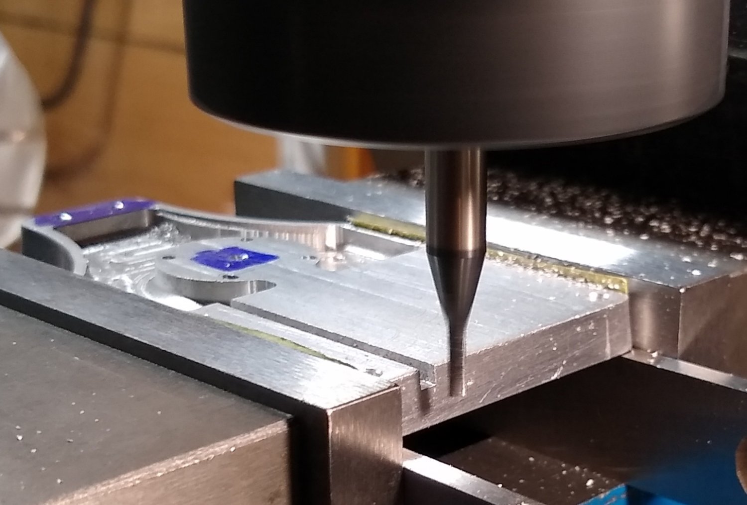
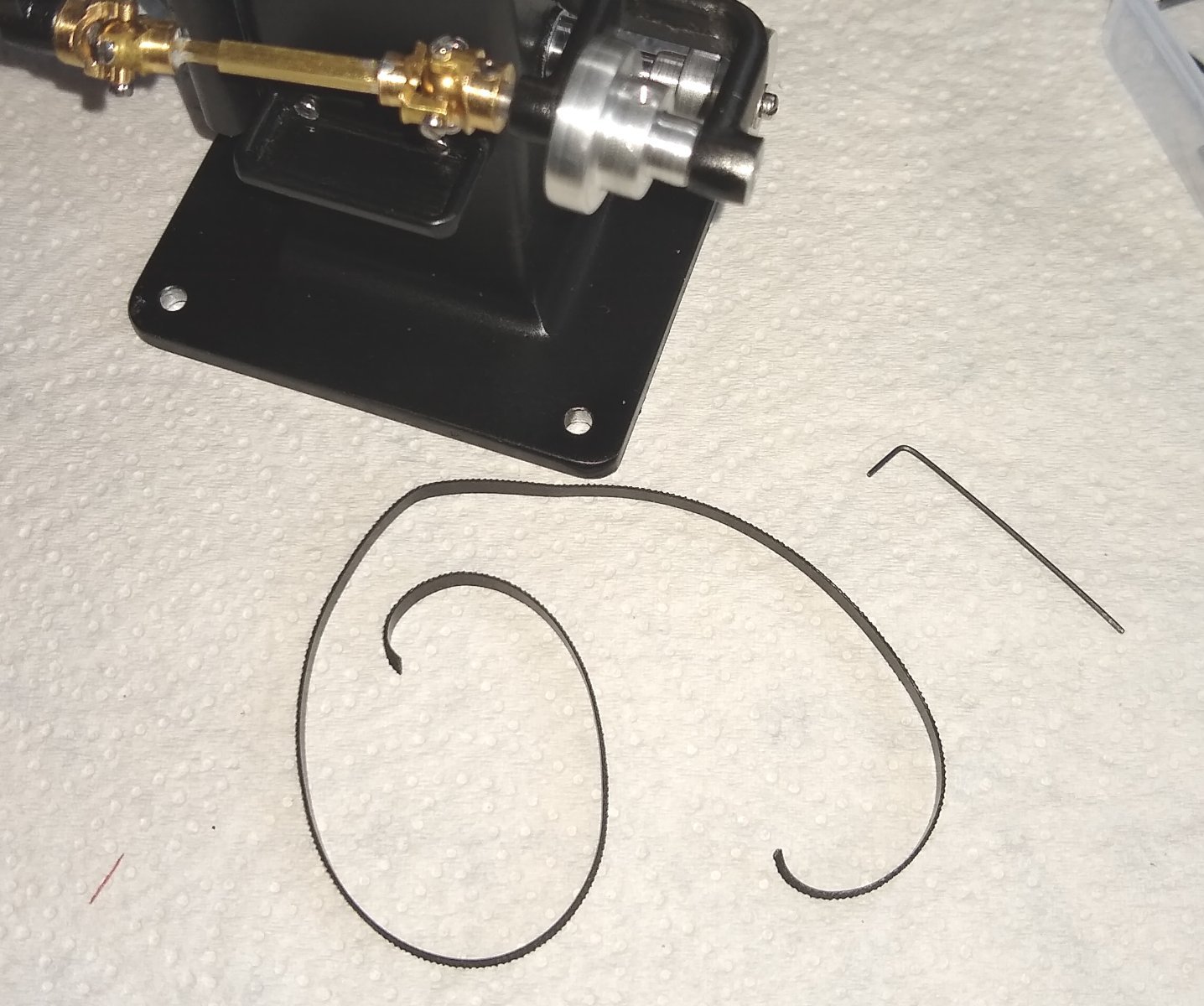
Below, flats are being added to Pt 23, the Spindle Shaft.
Below. One of the last things to do was add the two Belts, Pts 41. The drawing calls for them to be cut to length, with a slight overlap, then the overlaps super-glued together. The best way I found to do this was away from the mill. I firstly coiled the complete length to introduce a curve to the belt, then cut to length and then I weighed down one end whilst a cocktail stick with a dab of super-glue was applied to that end. The other end was carefully introduced and held down with finger pressure, making sure I rolled my fingers to stop the belt becoming part of my hand.

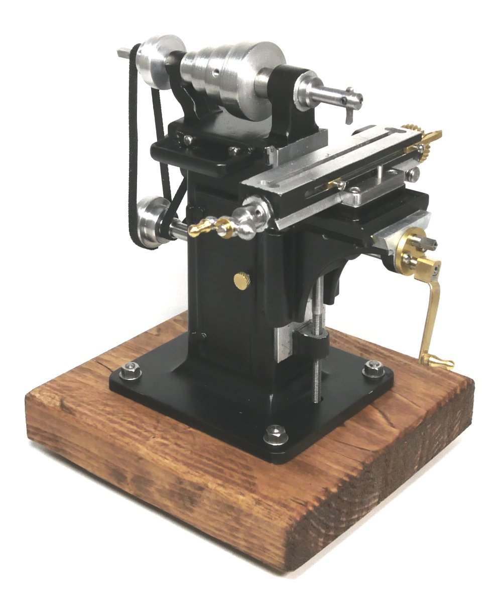
Finally, three pics of the finished Milling Machine. the wooden base is temporary till I find something a bit better- it did allow me to handle the mill more easily rather than getting fingerprints all over it.

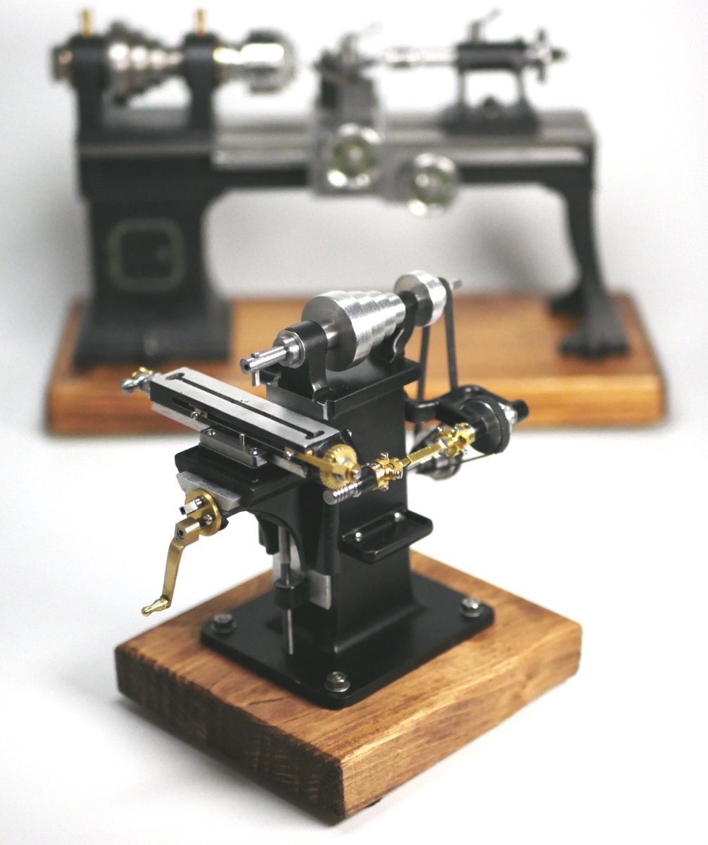
Below, for scale, one material removal device sitting next to another.
And the last pic shows the Mill about to meet it's workshop colleague, the Stuart Model Lathe.

All the moving parts of the mill function as they are meant to - the handle at the front moves the knee up and down, same handle also moves the saddle. The belt drives work, and move the bed left and right.
I will have another go at screw cutting the Feed Worm, Pt 29, and add a post about how I got on.
Final thoughts are:
- An enjoyable project that I would recommend. The Aluminium parts meant the workshop was much cleaner than when machining the cast iron of the Stuart lathe. However, in some ways, the Stuart product seems a bit more 'real'.
- The drawing set was fine and adequate for the task. However, some of the dimensioning was a bit strange eg more than one datum on parts when really only one should be used.
- The scale is claimed to be 1:12 but I always felt the real mill would be approaching 6 feet tall - the model is 4" high.
- I thought I had lost one of the 1-72 grubs screws (...there are no spares in the kit) but I had somehow managed to installed two grubscrews in the same pulley fastening hole .... I found that out late in the day....and it explained why I could never properly tighten that pulley 😉
- I probably should have paid more attention to accurately making the Bed, Pt 4. It is quite important to follow the drawing dimensions 100%.
Thank you for all the Likes, Comments and very useful feedback I received. It really does help bring a Build to life and also helps motivate me and helps me learn.
I'm not sure what my next project will be....I have a long list to consider and some workshop improvements that need doing first.
All the best, and see you soon 🙂
Richard
-
Thanks Roger,
Yes, I learned new stuff doing this one. Still a little whiles to go before it is fully 'finished', but I see the light at the end of the tunnel.
Some parts are now in the paint shop, others in the 'fettling' shop. So the pressure is off 😉
Richard
- Retired guy, Egilman, mtaylor and 1 other
-
4
-
Hi all,
I'm getting close to the finish line. This post covers the last remaining parts ie handles and shelves.
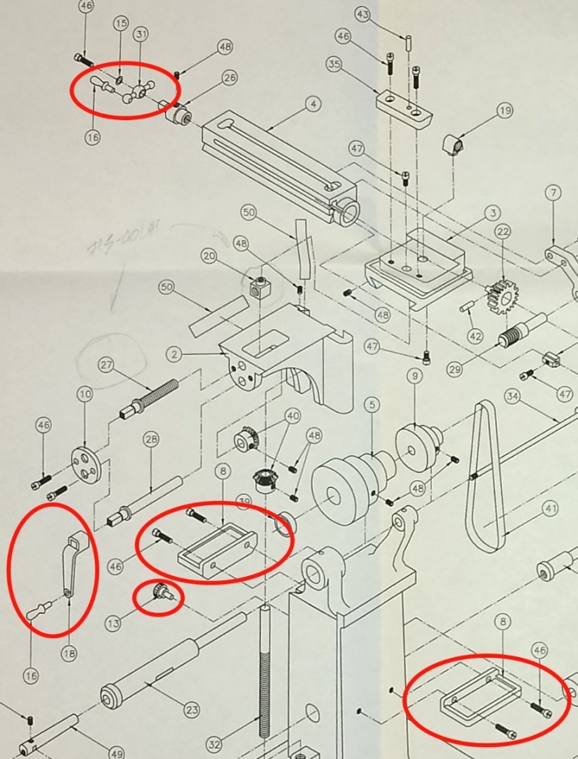
Firstly, the Crank handle for moving the Knee up and down. The same handle also moves the Saddle in and out.
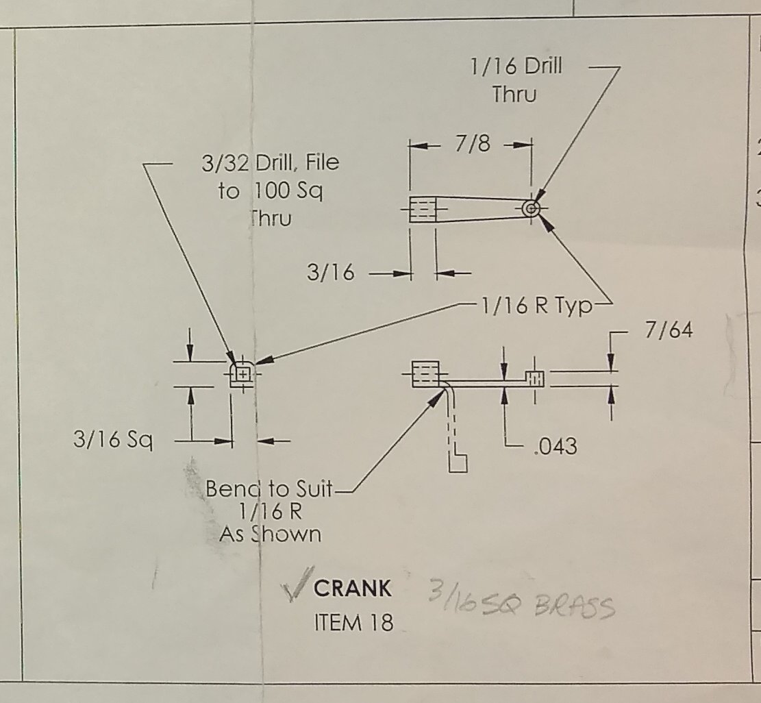
The drawing calls for the Crank to be made out of one piece of 3/16" brass. I decided to fabricate it out of three parts. I wasn't convinced I could bend the brass as depicted. I had some 1mm thick brass sheet that I did a test bend on and that bent fine - that convinced me to fabricate the Crank.
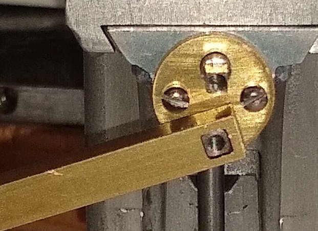
Below, the square hole was filed into the 3/16" brass stock. The end with the square hole was then cut off and cleaned up.

Close up of the square hole.
The arm and circular boss.
After bending the arm of the Crank, it was soft soldered on to the square end using a hot air soldering station.
Next was cleaning up and fitting the two tool shelves.
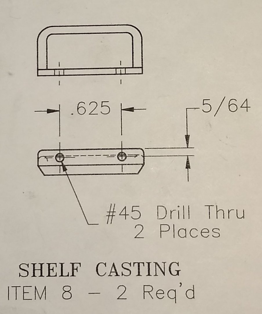
As seen below, one shelf fits near the top of the mill and the other on the sloping side of the mill Stand. That latter shelf had it's mounting face slightly angled on my mill so that it would lie horizontal when fitted.
Both the Crank and the Feed Shaft require handles, as does the 'door'.
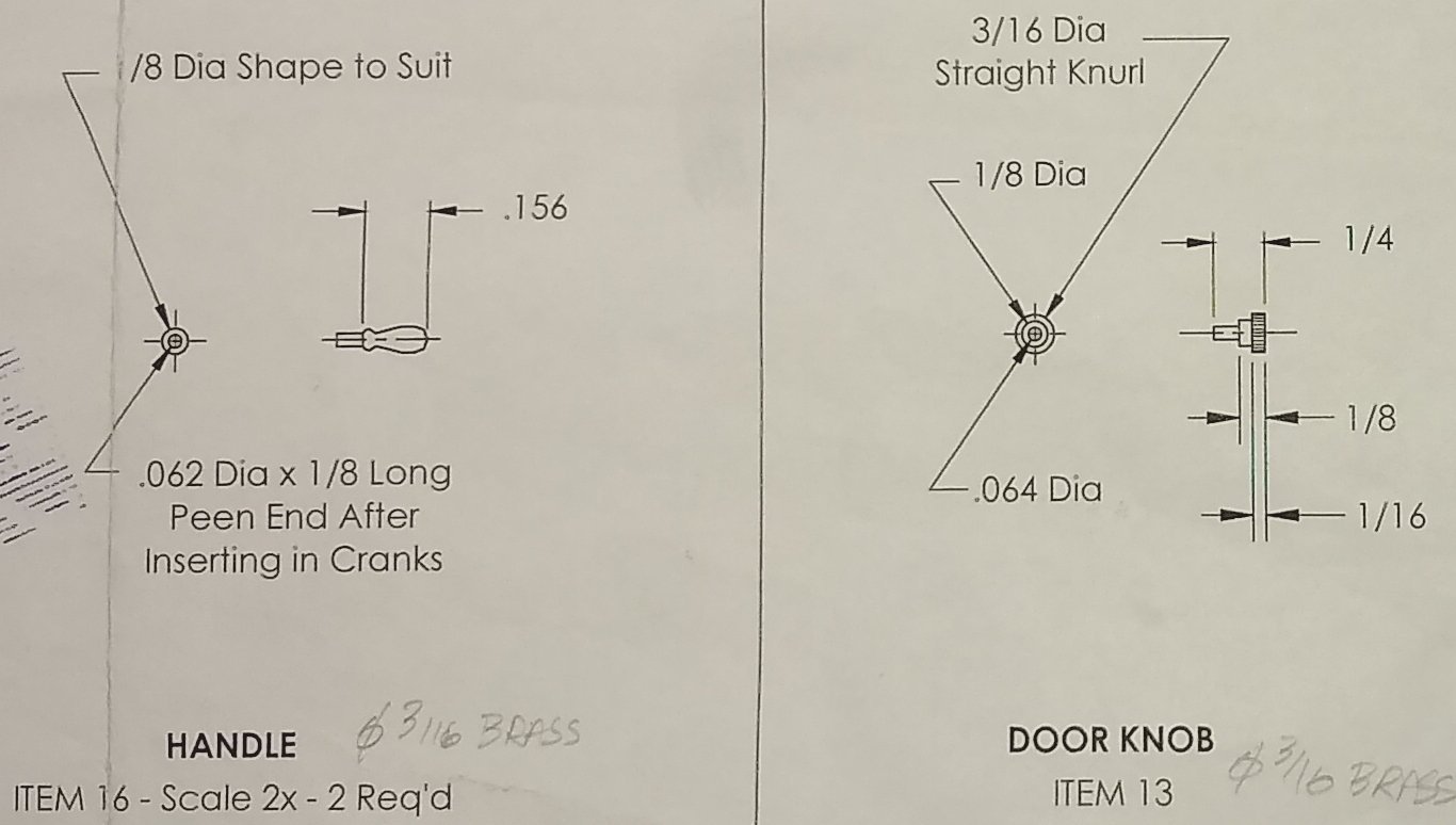
Below, the Door Knob and the Crank lying next to the mill.

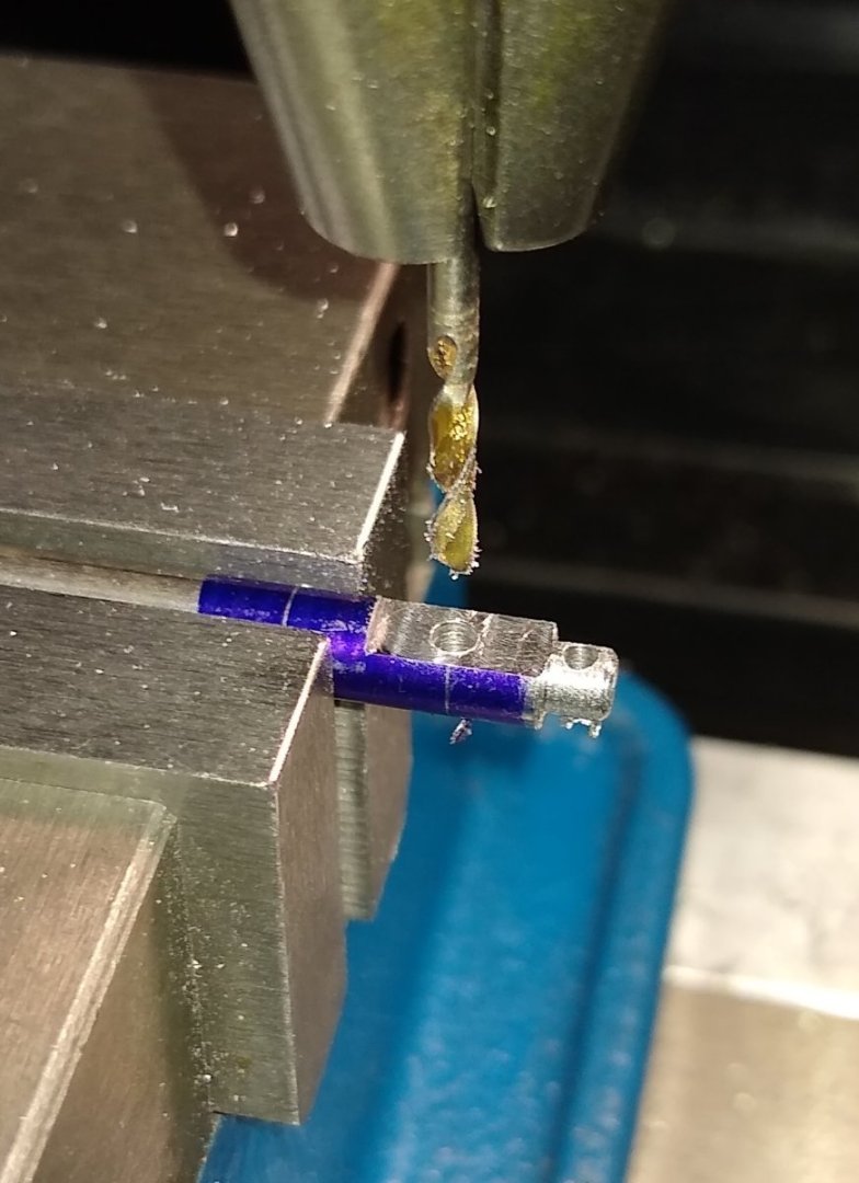
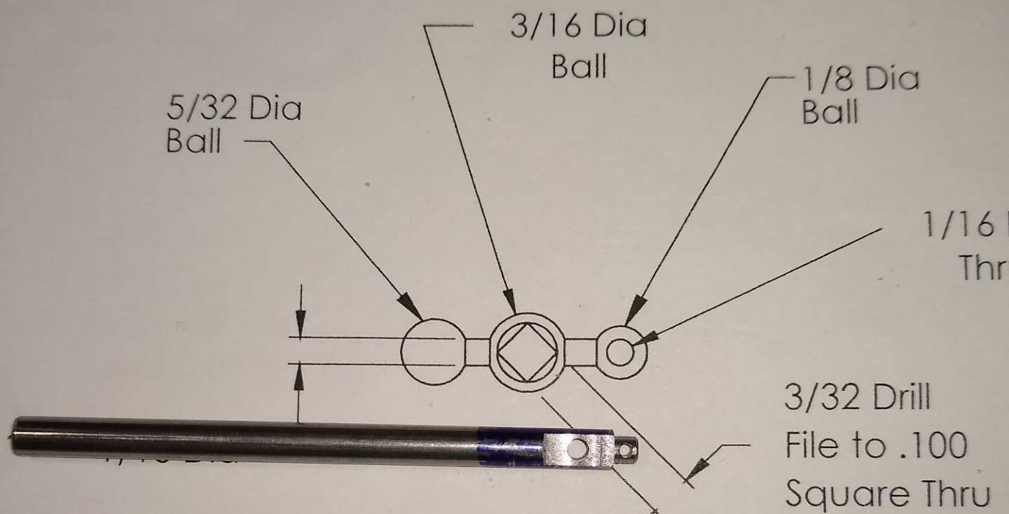
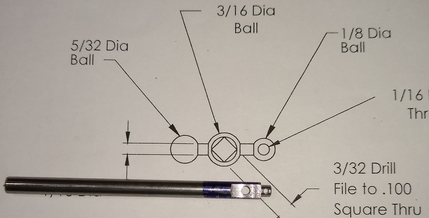
Lastly, the Bed Crank. Again, another square hole had to be filed...yup, I really need to get that broach made ;-).
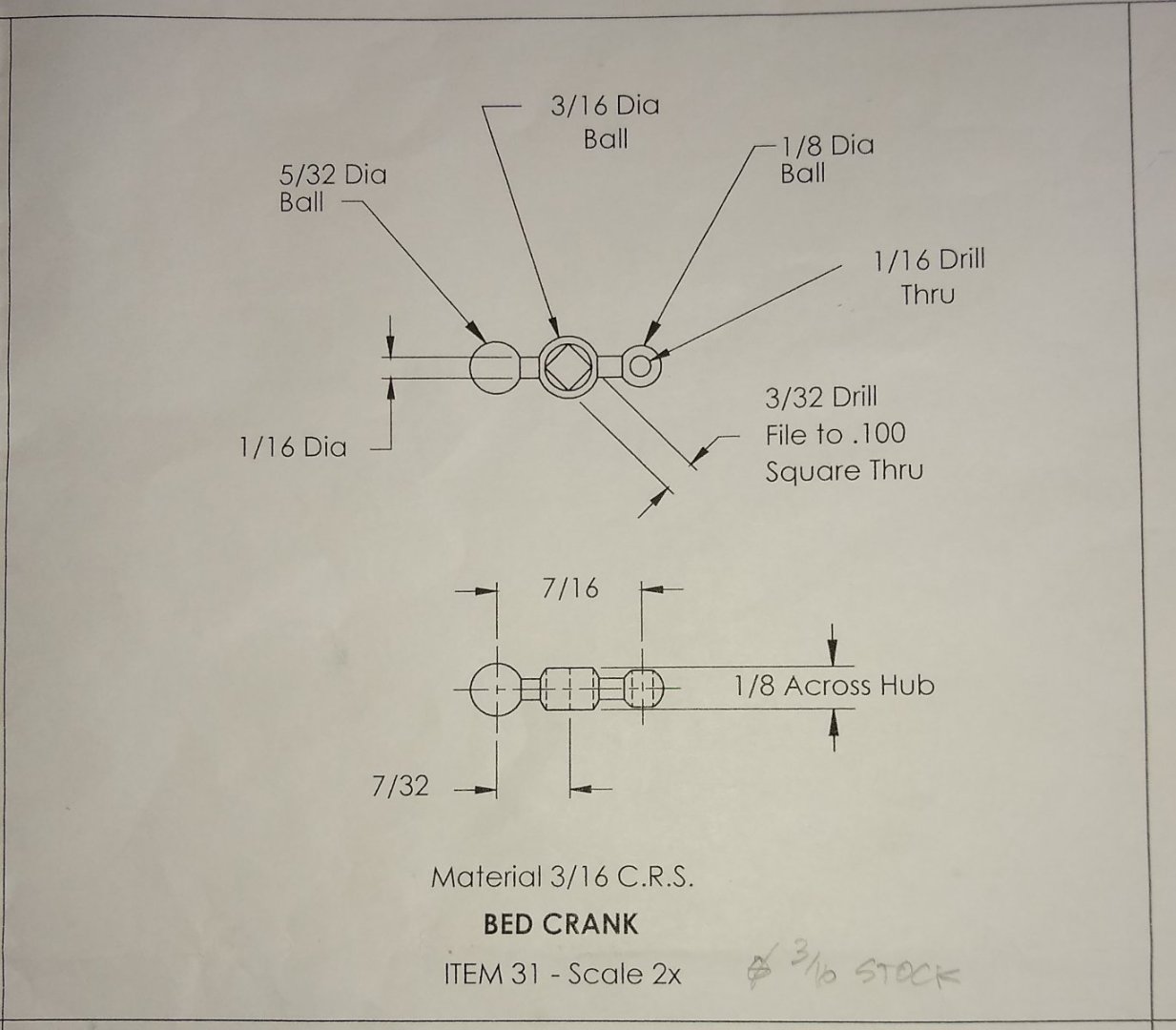
I had firstly turned the 1/8" dia end on the lathe. Then over to the mill to put the flats on the central section and drill the two holes.
Now ready to move back to the lathe for profiling the ball shaped sections.
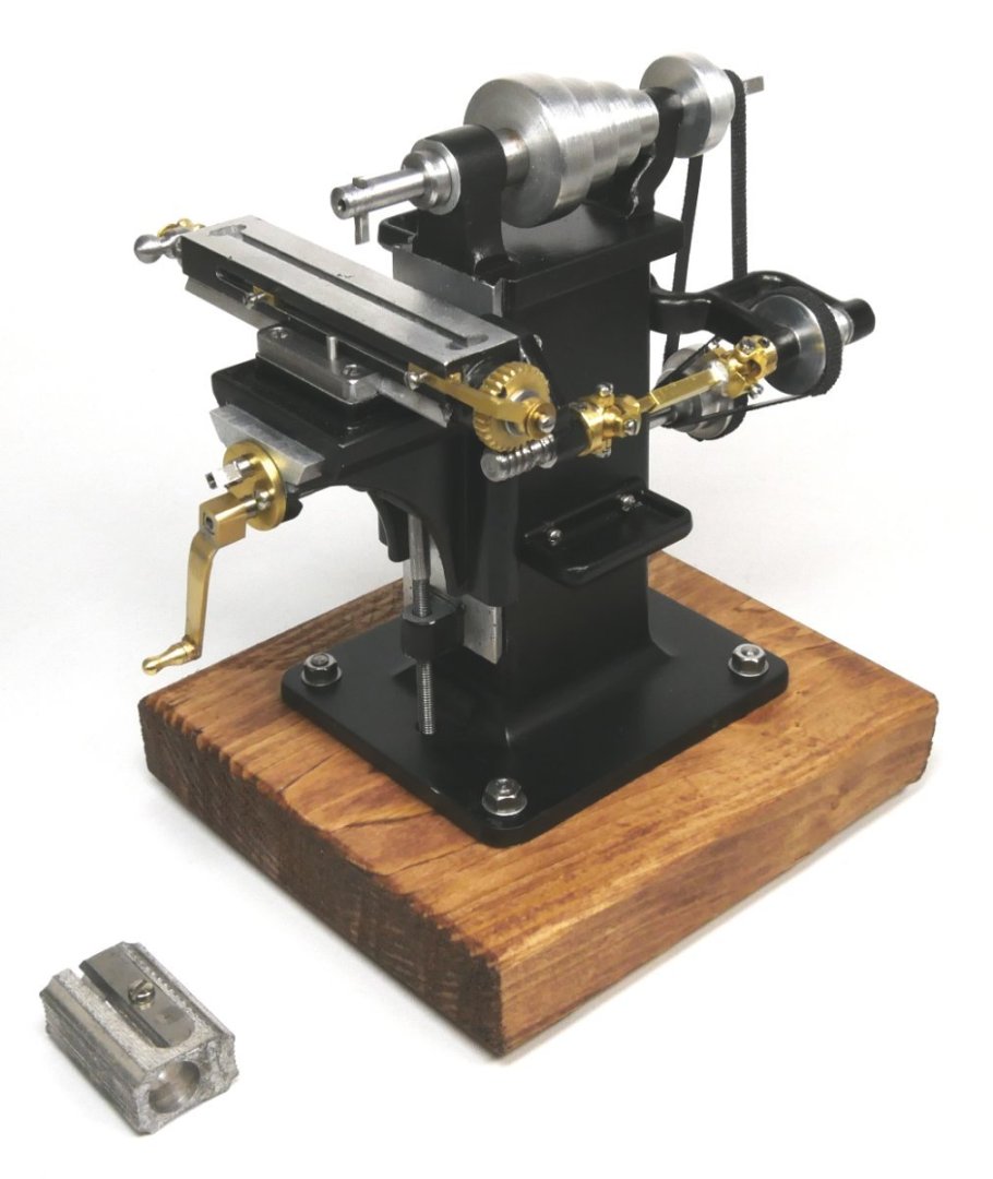
Finally, a couple of pics of the fully assembled mill (less driving belts, Pts 41)
The remaining work is to disassemble, fettle and clean, paint, make up the drive belts and reassemble. I'll post when that is done. I'll also have another go at making Pt 29, the Feed Worm and post progress.
All for now,
Richard
- FriedClams, VitusBering, mtaylor and 6 others
-
6
-
3


PM Research Drill Press by Rik Thistle - FINISHED -1895 - 1:12
in Non-ship/categorised builds
Posted
This week's post covers the remaining major parts. I also fitted the bevel gears at the top of the machine and did a number of other small tasks that I don't cover in this post.
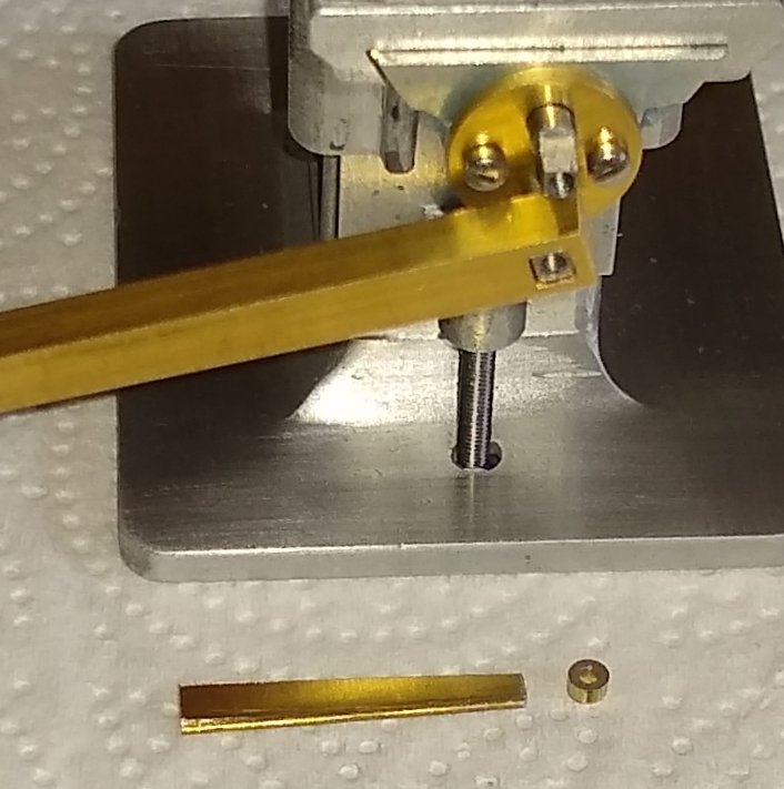
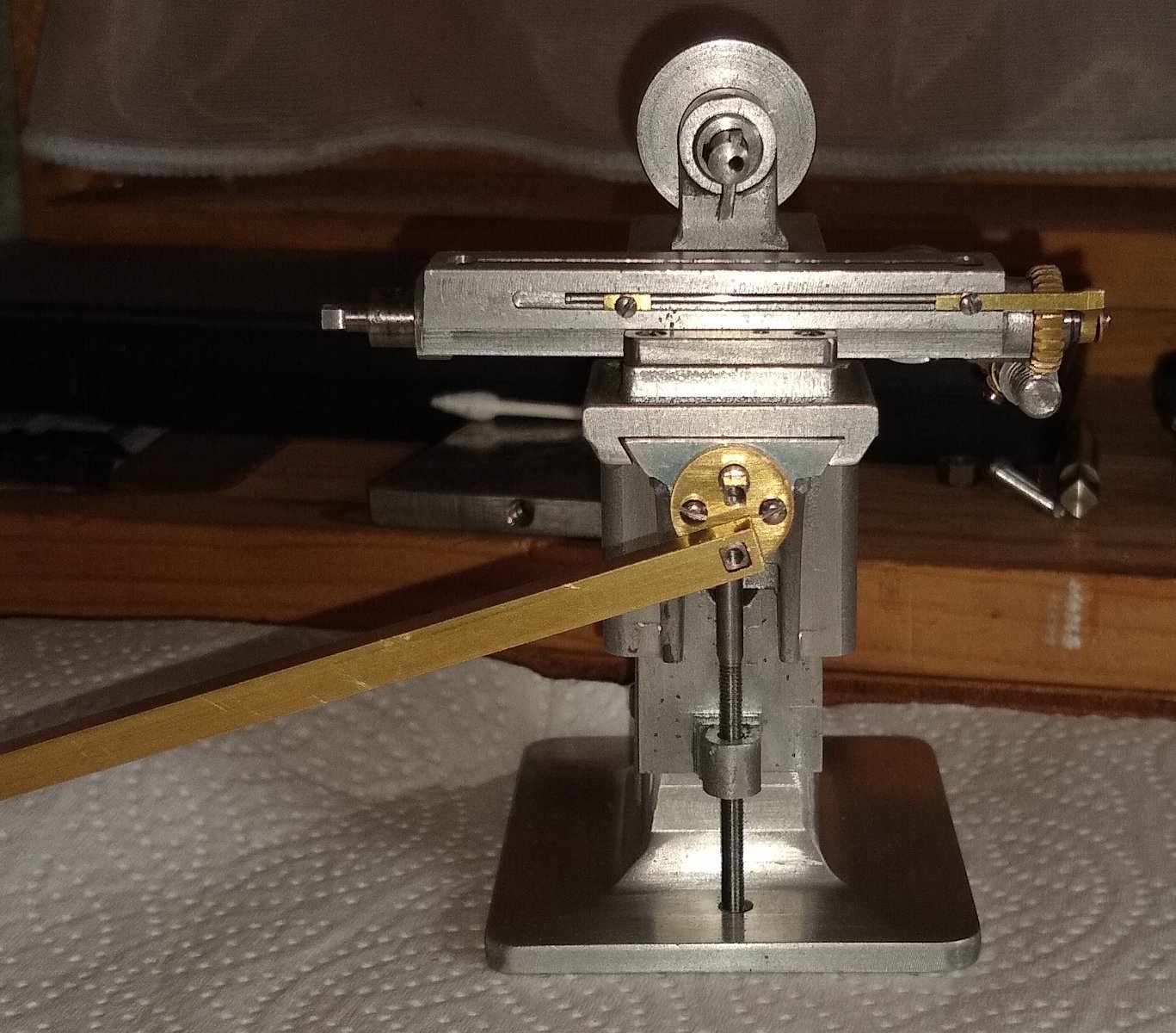
The Spindle Sleeve (Pt 30), requires two lockable Collars (Pt 24) to tie it in with the Spindle Shaft (Pt 22) that carries the drill bit up and down towards the work piece. Also made were the two handles (Pts 32 & 33).
Firstly, the two collars. Straighforward to make.
As usual, parting-off Mild Steel on a mini lathe can be a little challenging. However , this time it went well...I imagine I had the tool perfectly aligned and the right RPM. It's a tipped tool so no coolant was used.
Next was the Spindle Shaft. This was a slightly tricky part. A 1/16" groove at one end, a tapered hole at the other and a 1/32" through slot. Shown below also was a modified Junior hacksaw blade(0.018" thick) that I had used on a previous project - I intended to use that to join together the drilled holes to make the 1/32" slot. The blue arrow shows where Taper Shank (Pt 34), for holding the drill bit, fits into the tapered hole.
I used a Fine-Feed micro drill that fits into the existing drill chuck on the mill. This allowed me to apply very light finger pressure to the 1/32" holes which removed as much metal as possible for making the 1/32" wide slot.
After drilling 5x or 6x 1/32" holes in the Spindle Shaft I realised that I would need to link the holes before the hacksaw tool could be used. An old Safety Blade was used to partailly break one hole in to it's neighbour. A Dremel with a fine-point tool was also enlisted.
Eventually, the hacksaw tool could be pushed in to one end of the slot. After a bit of elbow grease the saw started to do it's job, and quite well. It's amazing how strong these blades are.
Drilling the hole in the Taper Shank for holding an old 1/32" drill I had....that drill diameter seemed to be the right scale for the Drill Press. A collet isn't designed to hold tapered parts, but the Shank taper is so slight at that size and diameter, it worked.
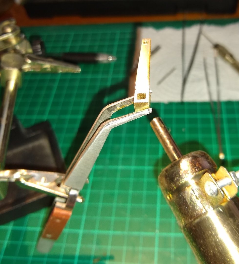
The drawing calls for the handles to each be machined out of a single piece of 3/16" square brass rod, but I decided to fabricate them - I felt it would be less risky. I soft soldered the parts together.
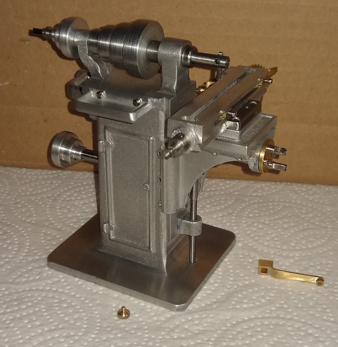
Finally, a couple of pics of most of the parts assembled together. One of the new handles can be seen upright near the top, the other close to the bottom.
I've still a few very minor operations to go plus some cleaning up, and then off to the paint shop and then final assembly. That will be my final post on this project in a week or two.
All for now,
Richard