HOLIDAY DONATION DRIVE - SUPPORT MSW - DO YOUR PART TO KEEP THIS GREAT FORUM GOING! (Only 44 donations so far out of 49,000 members - C'mon guys!)
×


Toolmaker
-
Posts
236 -
Joined
-
Last visited
Content Type
Profiles
Forums
Gallery
Events
Everything posted by Toolmaker
-
 Yes Todd, I agree. I can use them in my Sherline for the same reasons. Just not suitable for hand work.
 -
In my opinion these are not generally suitable for our hobby. The reasoning is; They are pcb drills. That’s “printed circuit board” drills. They are designed to be run at many thousands of rpm, usually in air spindles doing 20-40k plus revs. They are also designed to be held rigidly and securely in controlled feed environments. They have a high helix angle (the flute spiral) and if you can’t control the feed rate they will screw themselves into wood rather than cut through it. They are indeed cheap as they are hugely mass produced for the pcb market. Selling them to hobbyists is just up-selling. Take all the above reasoning and then add in that they are made from very unforgiving tungsten carbide which will accommodate almost zero flexing and after the first or second time you break one in an already fixed in deck fitting you will realise you should not have bothered. Stay with hss, high speed steel. You won’t be sorry. A decent pin vice and a set of high speed steel drill will give you great service. cheers Paul
-
Thanks for the suggestion Bob, BE's log is very impressive. I get the impression that he is happy to use something around 20% diameter of the main line which seems like a reasonable rule of thumb. I have a feeling I was off to a bad start with my post, likely mixing up the terms seizing and serving. Cheers Paul
-
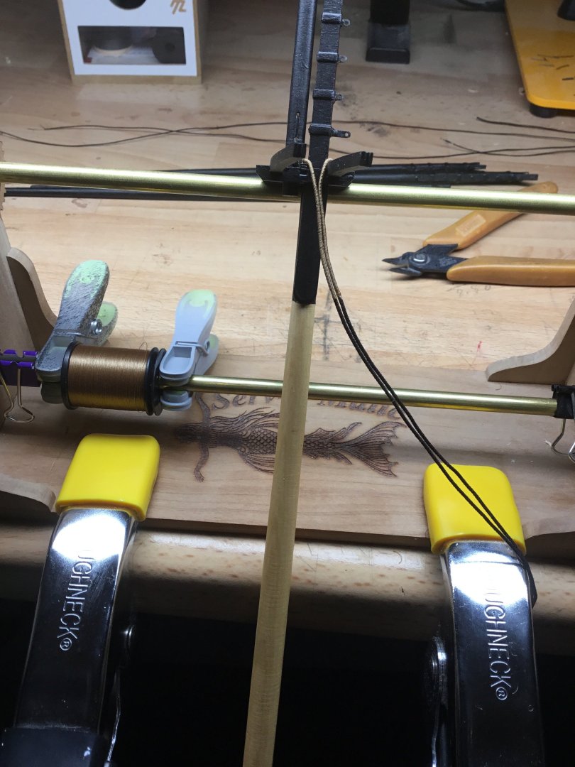
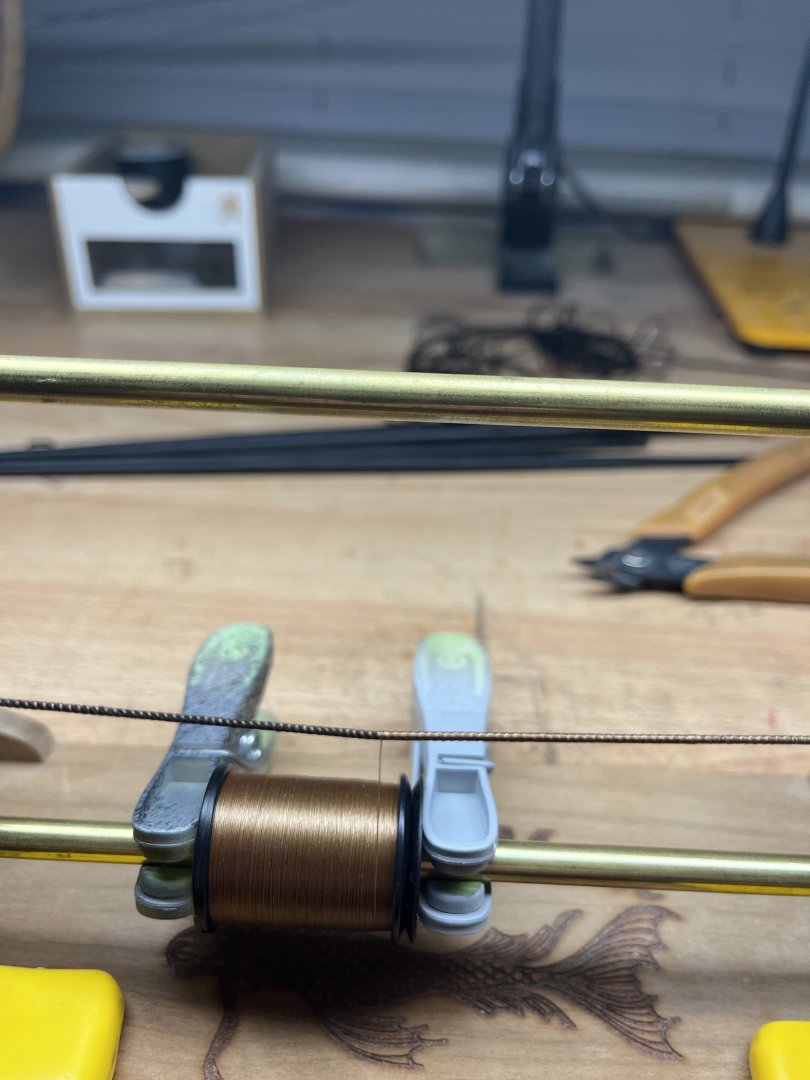
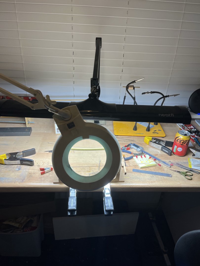
Resurrecting this 8 year old thread as it was the only one that came up in my search for some clear guidance. I am in the process of doing some seizing on my HMS Cheerful. This 2016 topic led me to try using 6/0 thread size which measures 0.05mm or 2 thou (0.002 inches). If I scaled this up it would represent just 2.4mm or .096 inch which is seems likely too thin. Should I be using something at least double that thickness? In scale the shroud is around 2 inch diameter and something like a quarter inch sounds more likely. Interestingly it’s the first time I have had to use magnification to help with a task since I moved over to wooden building from plastic 3 or 4 years ago. In this instance I think it’s the size of the thread rather than my eyes deteriorating further. I would appreciate any input on this. Thank you Paul
-
A first class base is nothing more than this fabulous build deserves. You have certainly done this kit justice. Thank you for sharing your efforts. Paul
- 840 replies
-
- 3
-

-
- winchelsea
- Syren Ship Model Company
- (and 1 more)
-
Bending hard brass.
Toolmaker replied to navarcus's topic in Metal Work, Soldering and Metal Fittings
It might be worthwhile getting a larger piece of brass and machine the part you require. Saw and files or power tools if you have them. I think this method would be more easily controlled and offer you a better chance of success. Brass is quite soft and files to shape quickly. -
Can I ask if any of sets 1&2 have been sent across the Atlantic, and if so can you indicate the cost of the carriage? Thank you.
-
OUTSTANDING Mini Drill
Toolmaker replied to Bill Jackson's topic in Modeling tools and Workshop Equipment
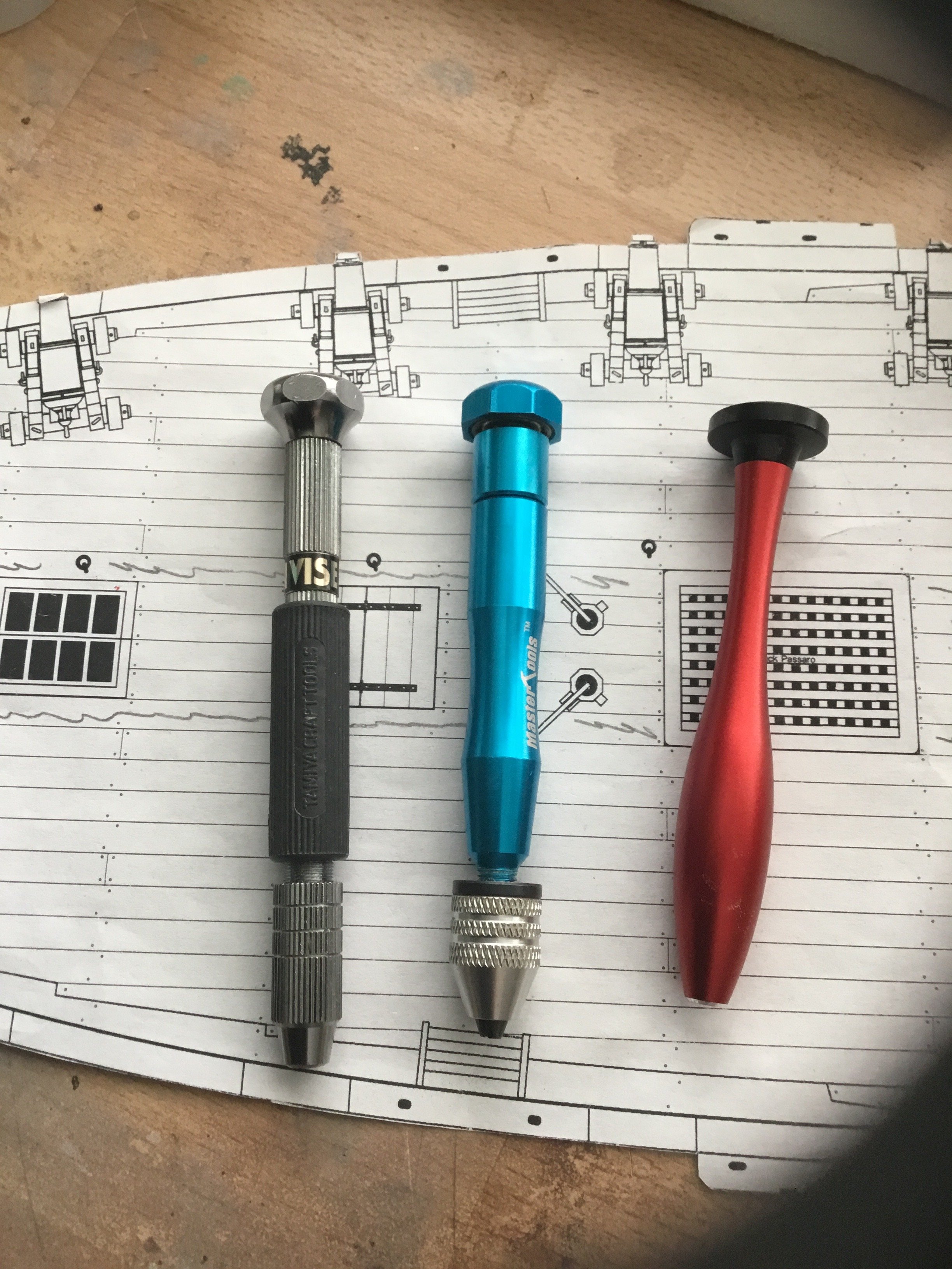
For me, that would be a non starter as it lacks the control necessary for much of the work we do on model ships. To use it one handed relies on pressure to create a screwing effect. If you use it 2 handed the workpiece needs to be fixed. Unless I have the piece fixed in a mill/drill machine then I always use one of these; Designed for one handed use, pressure easily controlled on start and break through. The blue one is my favourite as it has a mini chuck and the bearing system works well.
-
Citadel paint is designed for hand painting and it really is very good to use. On the other hand Tamiya acrylic (although it’s solvent based) is designed for use in an airbrush and can be difficult to hand brush. Add some retarder for better results.
-
Drill bit suggestions
Toolmaker replied to SiriusVoyager's topic in Modeling tools and Workshop Equipment
Any decent HSS, high speed steel, bit should hold up, hand drill or otherwise. Avoid carbide drills unless in a powered milling machine type environment. They are too brittle and prone to break easily when used in/for the purpose you describe. -
Apologies if this is drifting from your build but I feel it’s worth noting for people looking to build to scale. I just checked five different 25lb monofilament fishing lines and they were all different. The range was from 0.37mm to 0.52mm. Now 0.15mm which is .006 inch does not seem much, but the variation is actually more than 40%. Hence me suggesting it is better to know the required diameter rather than the breaking strain. Very nice start by the way.
-
The mark for the “planking band” takes care of this. Prior to marking any bulkheads you have divided the hull into x amount of planking bands with, usually, narrow tape. This is marked as the bottom of the planking band. You would now determine how many strakes from your existing planks to the bottom of the band and mark your bulkheads accordingly. I understand you are up to date to this point. As for marking the filler block, you are still looking to mark the same number of strakes to the bottom of the band. Divide the distance from existing planking yo the bottom of the band by the number of strakes and mark up. if you wanted to mark all along the filler block you can lay your paper from the mark on bulkhead 1 to the mark on the rabbet and pencil along the paper top but I don’t find that necessary. if I have missed the point of your question then I apologise for misunderstanding it. Regards Paul
-
Outstanding high standards Glenn. Every picture an inspiration. I have high ideals, which of course is not the same as high standards, but I would be beyond joyous if able to match those standards you are displaying. I am learning my trade on Cheerful but 2025 will be Winchelsea year and along with Chuck’s monographs I shall be having your build log with me as escort. Thank you Paul
- 840 replies
-
- 3
-
-
- winchelsea
- Syren Ship Model Company
- (and 1 more)
-
I think using the breaking strain of the line as a size measurement can be misleading. It would be better to look for a correct diameter rather than the breaking strain. That way you would also know what size drill to use. Alternatively, measure the line with a vernier and buy the drill to suit.
-
Hey Nic, Don’t be taken in by that fella above called No Idea, he does have an idea. I would concur with him and go for a Vanguard models kit. In a large part because they are in the UK and if you have any issues they are not far away. My current builds are from USA sourced suppliers but I got a couple of Vanguard kits under my belt first. I would suggest this kit to test your mettle; https://vanguardmodels.co.uk/product/fifie-lady-eleanor/ The hull shape gives you the best chance of success at this early stage and you can probably buy the kit and all the tools and paints required for under £200 quid. If you go for it and need advice along the way, just shout out. it was my first dabble at wooden boats and I have lots of photo’s etc Good luck bud Paul
-
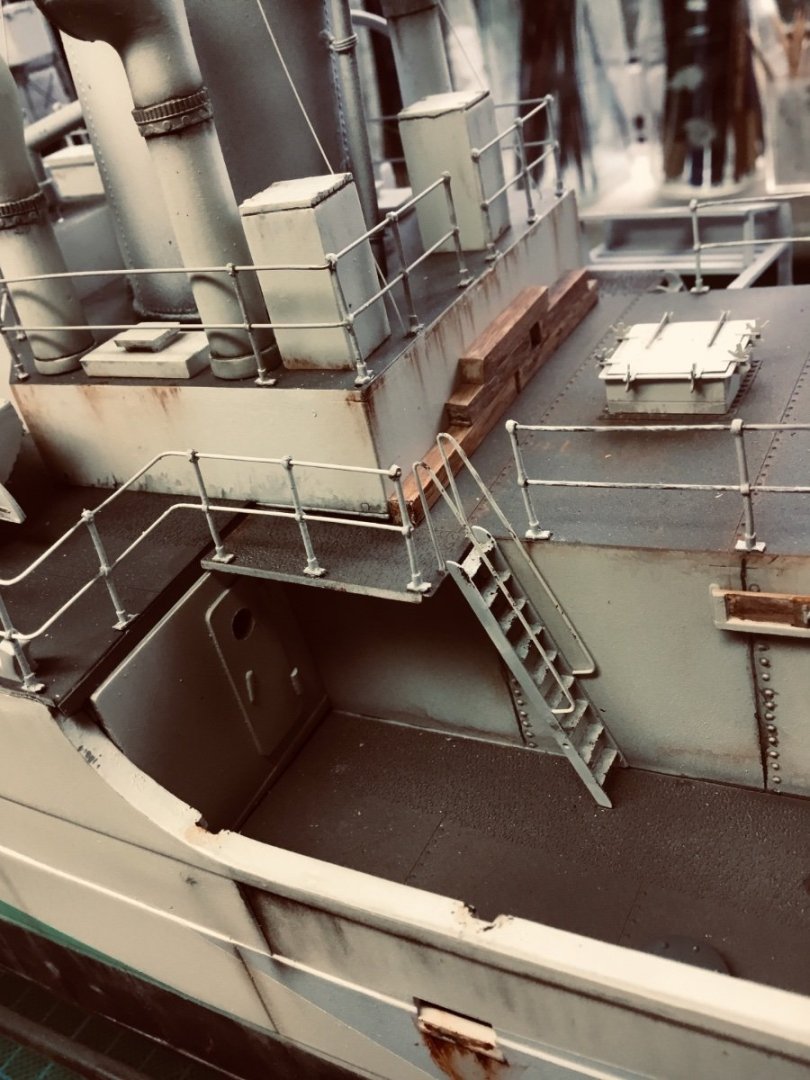
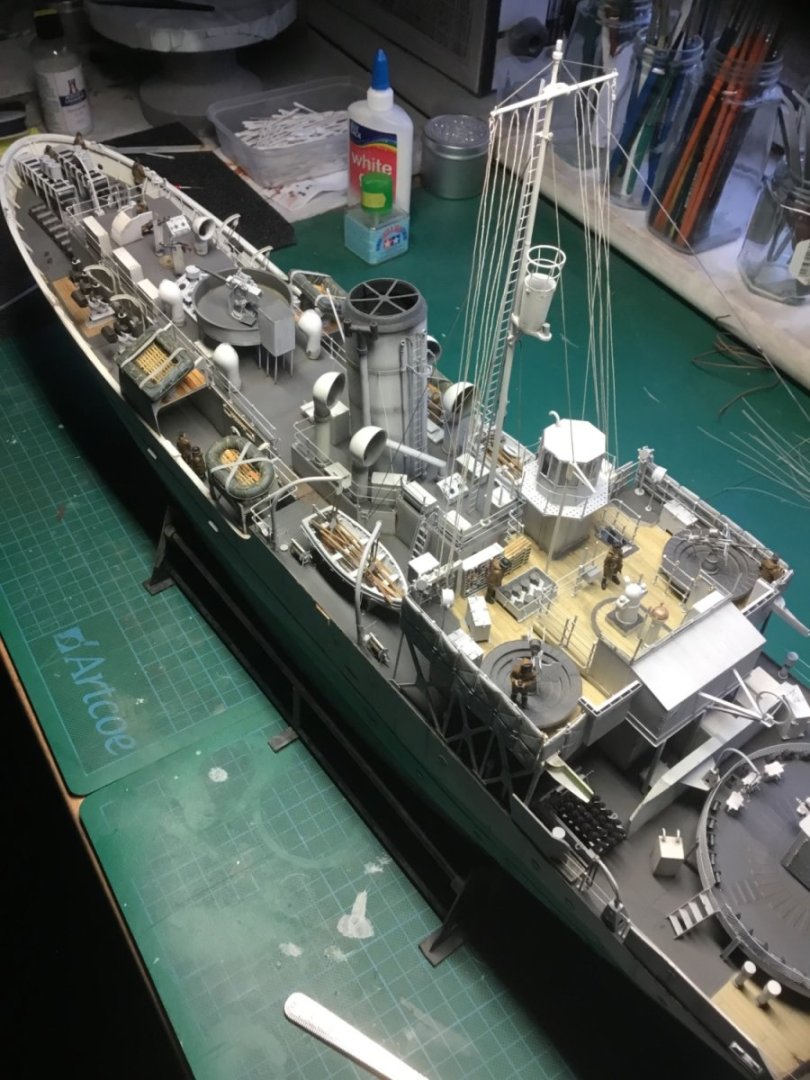
I feel like I’m about to be given a most obvious answer, but as I don’t know, I have to ask. From a ship design point of view, what was the thinking behind the cupola? Why bother?
-
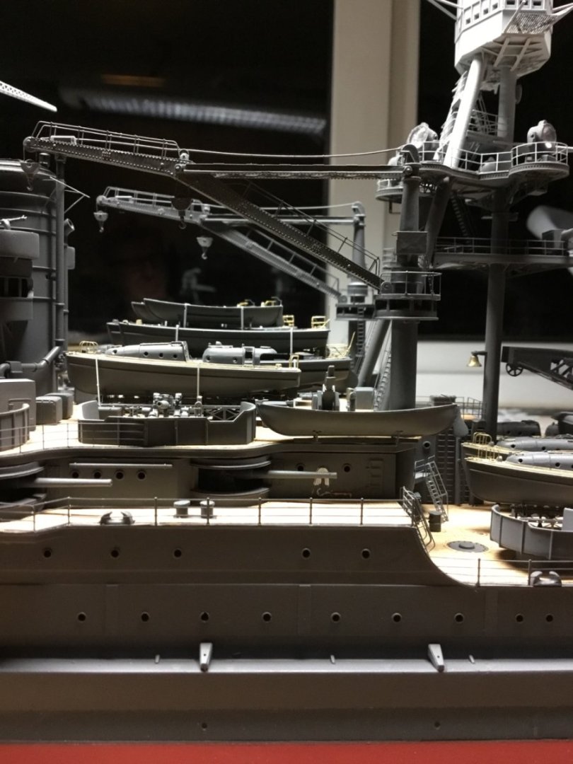
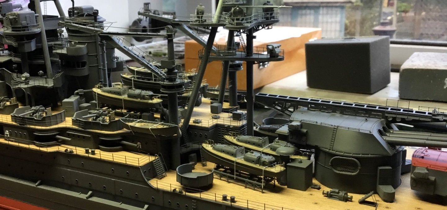
It’s the angle that the photograph is taken that is misleading you. It’s the same detail in both pictures.
-
Grainy, if there is such a word. Its no surprise as 3d printing of metal is termed "additive manufacturing". The process is done from grains of metal. It is generally done for very bespoke products and oft times it is more cost effective to machine the parts This video gives a good overview about the process and why it can be expensive. That said, cost are coming down with basic machines now affordable to hobbyists. I'm certainly no expert but have bought sintered metal products in the past.
- 1 reply
-
- 8
-
-
Making lifeboat small mast for 1:200 Yamato
Toolmaker replied to Olaf's topic in Metal Work, Soldering and Metal Fittings
Certainly 0.4mm/0.020” sizes in straight brass wire are available as I use it myself. -
Nice barbie mate. Great planning and equally good execution.
-
Mini Bench Drill Press
Toolmaker replied to Gregory's topic in Modeling tools and Workshop Equipment
The Sherline vice operates in the way you describe wefalck. This is a link to it for sale in the USA. https://www.sherline.com/product/3551-milling-vise/#description -
My guess would be that the op was referring to profiled router cutters.
-
A few seconds with one of these is great preparation prior to soft soldering brass photo etch. Refillable regarding the fibre glass brissles. Your right though Rob, thinking about it I do now wonder about the safe usage, albeit a bit late having used them for years.
-
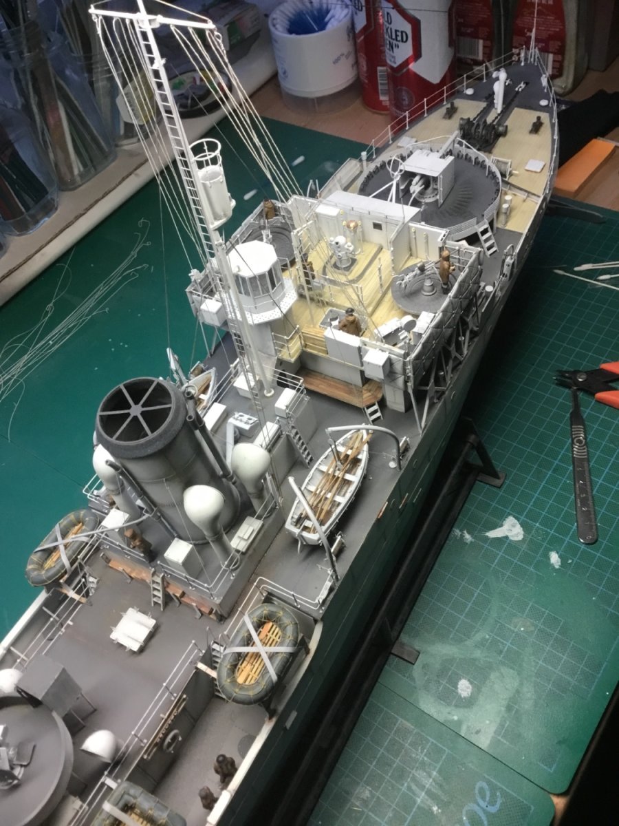
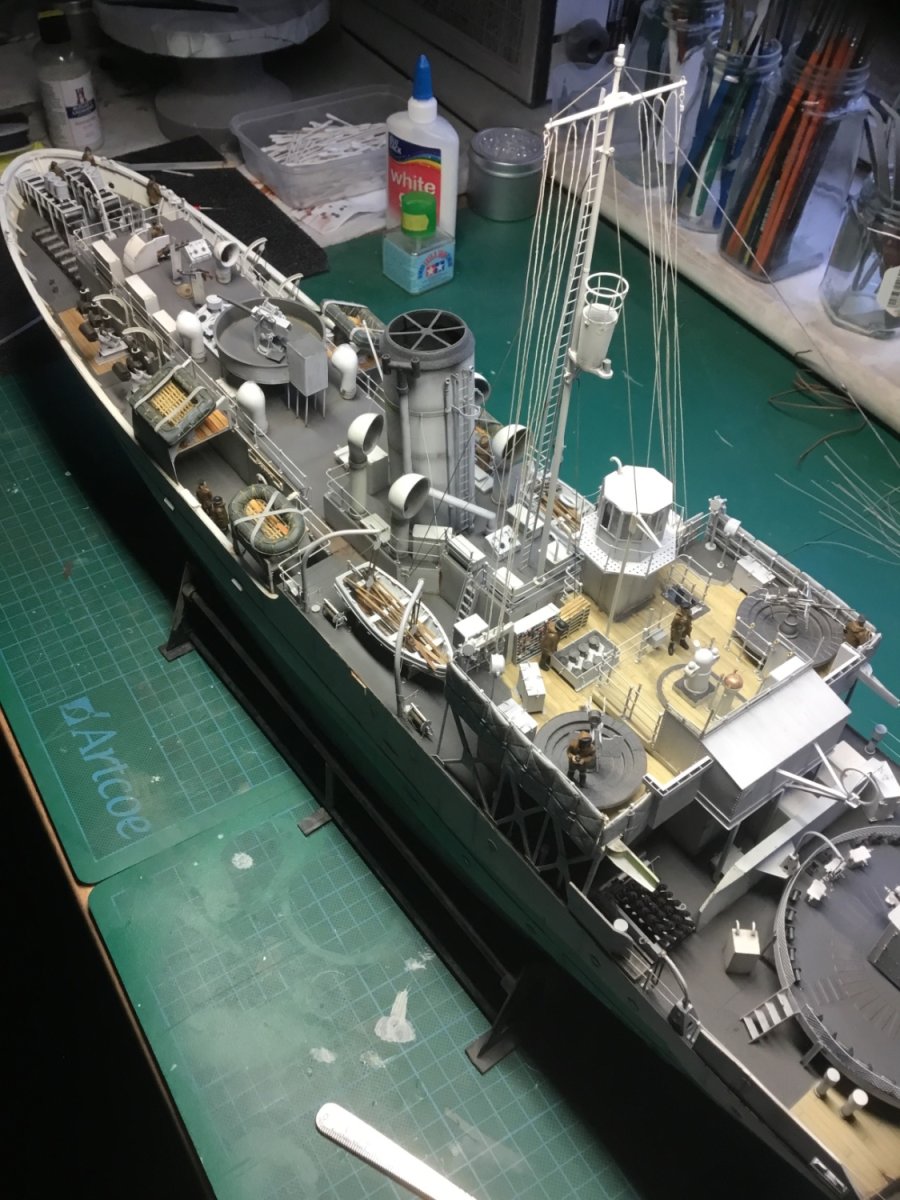
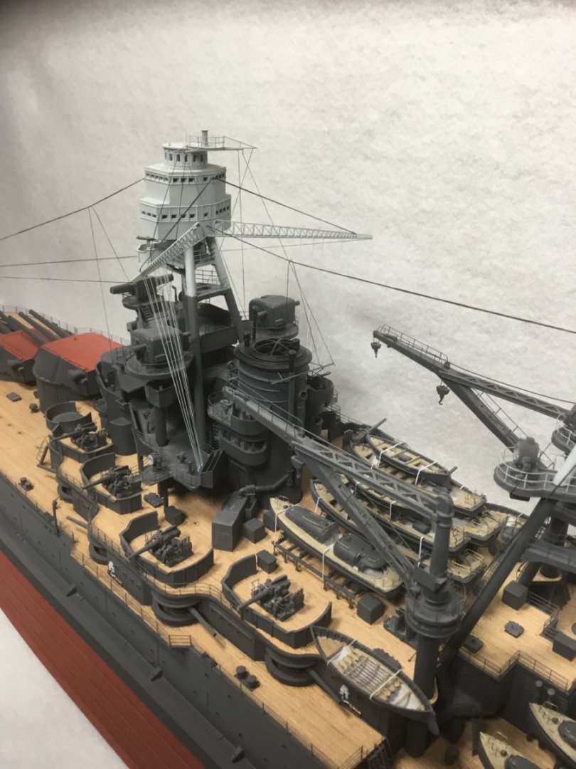
I transitioned from plastic to wooden ship building around 5 years ago. Prior to that I had built 2 plastic ship models, the battleship Arizona and a Flower Class Corvette. Arizona; Arizona detail Arizona finished Flower Class Corvette Flower Class Corvette lifeboat FCC finished FCC finished stern


-
Pulled the Trigger == Lathe coming
Toolmaker replied to kgstakes's topic in Modeling tools and Workshop Equipment
I can only offer advice based on industry standard machines. Although I use a miniature Sherline milling machine I do not currently own a model makers lathe. That said, in the past, at the spindle end I have used 2 jaw, 3 jaw, 4 jaw and collet chucks. Most of the 4 jaw chucks have had independent jaws but self cantering 4 jaw chucks are also common. I have worked with a 4 jaw chuck in a 3 jaw chuck and with a 3 jaw in a 4 jaw. Regarding soft jaws and their use. Soft jaws are available for many 3 jaw chucks and certain collets systems have soft collets available. Soft jaws/collets are predominantly used for second operation work. That’s when you have worked on one side of a part but still have work to do on the other side and want to hold it in an accurate manner. Most 1st op work would be done in hard jaws. So most soft jaws become stepped. You can step the inside of the jaws or the outside. The jaws have to be locked firm when you machine them. For utmost accuracy If you are stepping the inside of the jaws (to hold on the outside of your part) then you should clamp a piece of round bar in the chuck and bore the jaws to the same diameter you want to hold your part or very slightly larger. Conversely if you want to hold on the outside of the soft jaws you should hold a ring on the outside of the soft jaws. This method is to give better likely concentricity accuracy but in practice hobby machinists will likely clamp the jaws the same way as before, on a piece of round bar. Full soft jaws, sometimes called pie jaws, are useful when holding thin walled parts. These parts might likely distort if you held them in traditional 3 jaws, soft or otherwise. One instance when you might wish to bore soft jaws through is when you want to avoid damage from hard jaws, whilst wanting good concentricity from one end to the other of a shaft. You can also have soft jaws for your milling vice allowing you to hold specific shapes and without needing parallels. To be honest, most of this is referencing model engineering rather than wooden ship building but take it as a snapshot of soft jaw usage. I’m sure lots of usage videos are available on the internet. Most important message is work safely. 50 years ago I was told by a foreman “you can walk on a wooden leg, but you will never see out of a glass eye”.