HOLIDAY DONATION DRIVE - SUPPORT MSW - DO YOUR PART TO KEEP THIS GREAT FORUM GOING! (Only 36 donations so far out of 49,000 members - C'mon guys!)
×


Toolmaker
-
Posts
236 -
Joined
-
Last visited
Content Type
Profiles
Forums
Gallery
Events
Everything posted by Toolmaker
-
 Hi Fred, I really like what you have accomplished here and I will be extremely happy if I can match your standards with my own build. You are just finishing and I am just starting out which is great for me as I can use your example (along with a couple of others belonging to builders represented on this very page) to inspire me along the way. Thank you Paul
- 113 replies
-
- 3
-

-
- Cheerful
- Syren Ship Model Company
- (and 1 more)
-
Richard, You turned that around in fine style. As a hobby, there is no such thing as a mistake. It’s just another opportunity to practice. Can I ask what do you think of the wixey angle gauge. I’m still old school protractor here, but I can see the advantages. Thanks Paul
-
US 6” gun by RGL - FINISHED - Panzer Concepts
Toolmaker replied to RGL's topic in Non-ship/categorised builds
Having done my fair share of weathering I have to say “yes”. ”Yes” I would be extremely happy if this were my work. I think it’s superb and thank you for the entertainment Cheers Paul -
Great result Rob. Those figures bring it all to life giving a real sense of scale. I’ll keep an eye out for your next build Thank you Paul
-
Thanks for taking the time to reply on this. That’s interesting to hear and gets the imagination working in consideration of the old craftsman. Regards Paul
-
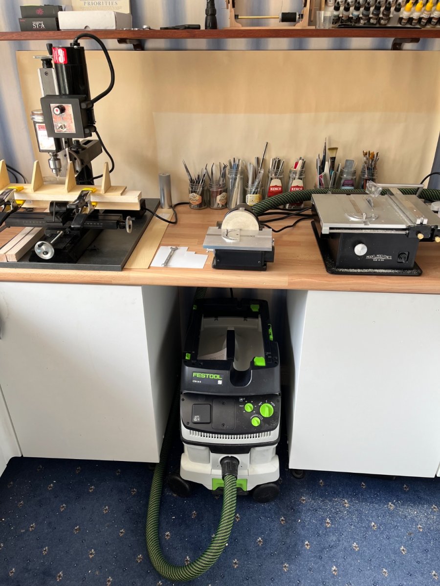
I think you are maybe missing at least one set of circumstances when “hobby sized” machines are the correct choice. I spent my working life using full size machines but as a retired hobby machinist my decision was to buy miniature machines. My Byrnes saw and sander are miniatures and I have recently purchased a sherline mill. I don’t have large workshop facilities and have commandeered the spare bedroom so I don’t think getting a full size set of machines up the stairs would wash with my better half nor would any sort of machine lubricating regime. Lack of floor space also meant bench top machines. The sherline is a good piece of kit and I can drill 0.5mm/0.020” without issue using the standard feed. Today I was taking 4mm/0.160” deep cuts in boxwood and holding better than 0.0015” tolerance. So yes to it being small but it certainly behaves like a full size machine. There are limitations, but there always is. You might say that as I’m working in 1/64 or 1/48 then my machines could be the same scale 😂 So for me it’s the usual advice; get the biggest and best that is practical and within budget. Thank you Paul

-
US 6” gun by RGL - FINISHED - Panzer Concepts
Toolmaker replied to RGL's topic in Non-ship/categorised builds
Very nice work sir. To build a realistic level of weathering takes numerous layers requiring patience and control. You have bucketfuls of both. Fab work. Thanks Paul- 235 replies
-
- 10
-

-
-
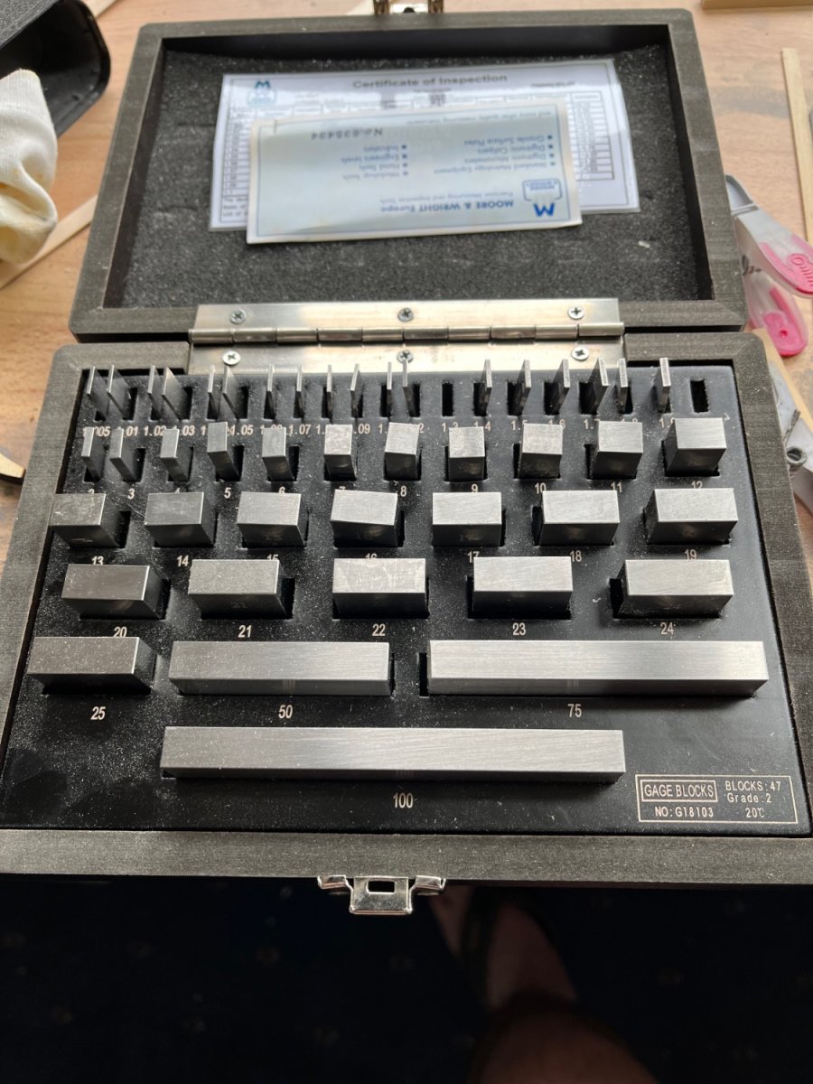
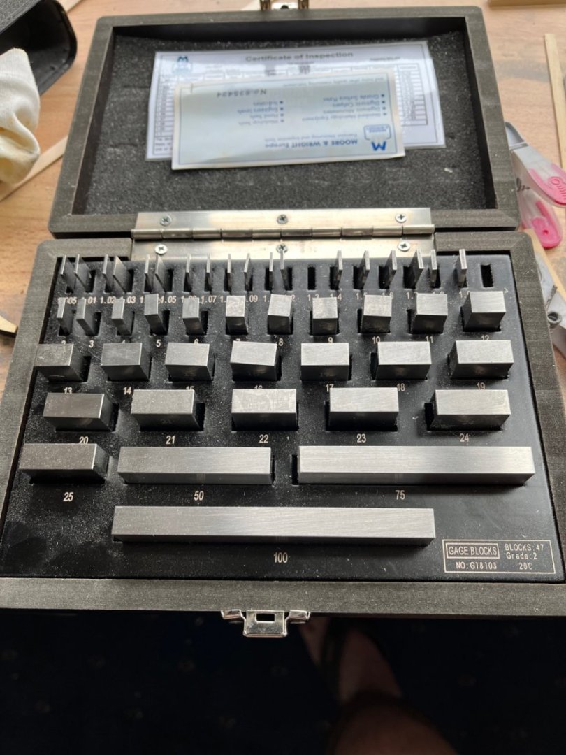
Thanks Bob, trying to be helpful is the aim really. I’ve posted a bit on soldering and metal prep as that’s what I know a little about. Being a recent convert to wooden models I hoover up knowledge from here so only seems right to offer some suggestions that aI am more knowledgeable about. To close my input here (unless any questions arise). I’d say the scribing block and some basic slip gauges are very useful basic editions prior to the full digital height gauge. I’m fortunate to also have a basic set of slip gauges. Mine are metric. A 1mm slip sat on one gunport; A 1.3mm slip sat on the opposite side; We have interference with the scribe point so the difference in height from the build board is less than 0.3mm or 1/2” in real world at 1/48 scale. Good enough for me. Im glad you found it interesting. Thanks Paul
-
Recommended pins for planking?
Toolmaker replied to Capella's topic in Modeling tools and Workshop Equipment
Although I have changed my methods over previous builds, these sort of pins can help with second planking as you are not putting them into the finish planks; regards Paul
-
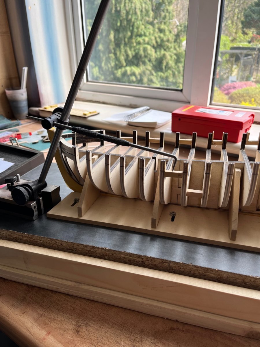
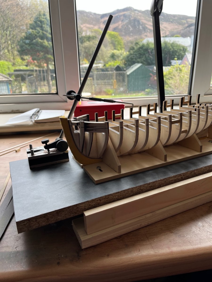
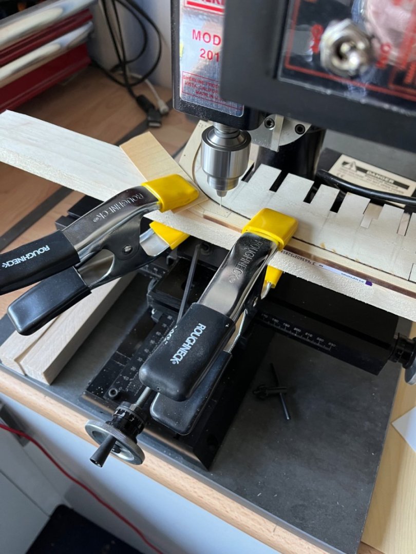
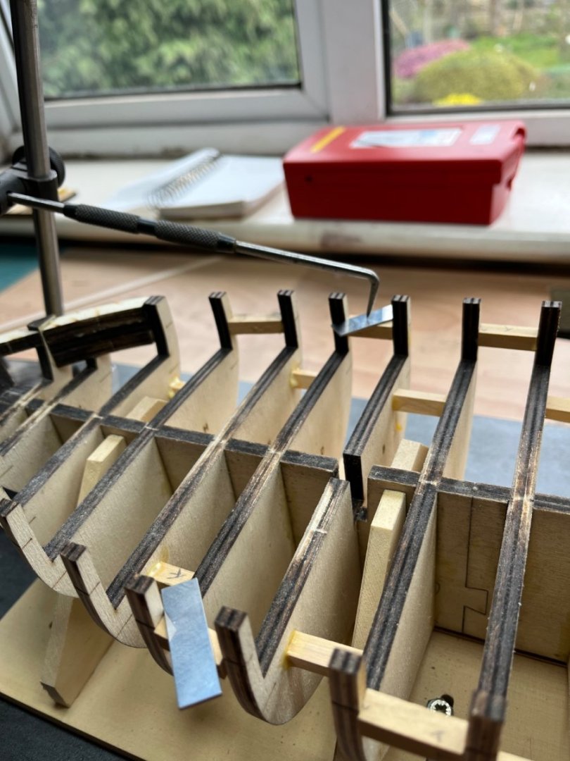
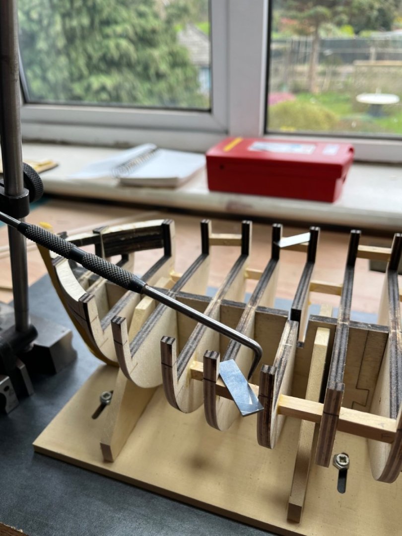
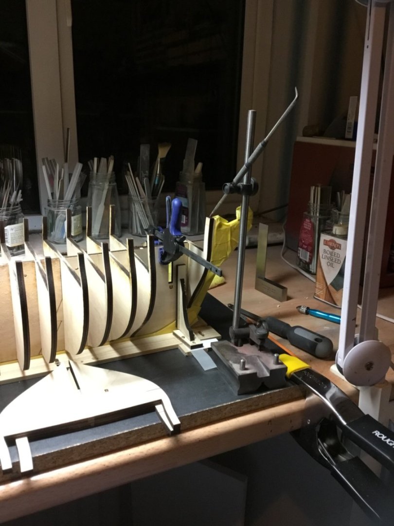
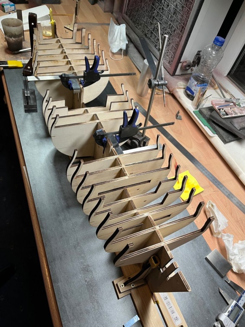
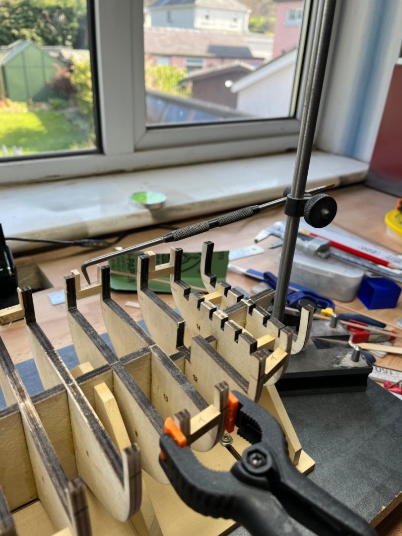
At this time I am fairly new to both wooden ship building and MSW. As such this is possibly a risky post as I might be either preaching to the converted or just plain wrong. Although having completed just three builds, I have no doubt that the journey becomes akin to “wood engineering”. I have two 1/48 scale builds on the go and am committed to trying to work within +/- 0.5mm which equals about an inch in real world. I’d be interested if anyone can quote records with regard to accuracy of the day in the early 19th century. Enough of the post introduction and on the the meat of the subject; I have not seen much use so far for this tool on MSW but I feel it is under utilised. I see lots of spirit levels but sometimes think the user may not be getting the results they believe they are. My two current builds have been set up on build boards made from spare kitchen cabinet panels. They are very flat and as spare, also very cheap. The top surface of the build board then becomes the datum. You don’t need to worry if your fixed work surface/table isn’t flat or level, just work from your build board datum. I think with a little experience it is easy to work within 0.2mm or 0.008”. The tool has different names depending who tells or sells it. To me it was a scribing block used for marking out but it could be a simple height gauge or comparator. You could attach a dial indicator (known as a clock) or just a simple scribe as I have. Above it is being used to adjust the heights of the bulwarks. In this instance I am not setting a known height, just matching the height of starboard and port. This next picture I am matching gun port heights. Using the fine adjustment screw whilst moving the scribes point back and forth across the gun port until a touch is felt/heard. You then slide your scribe block to the opposite side and set your wood height accordingly. You will find you are quickly working within very fine tolerances without effort. The following picture looks to show a point I am trying to make. I have tilted my build board by an inch or so. Tilting it makes it easier to see the laser etch marks used as guides on the gun ports. Using a spirit level in this instance would be inappropriate here, but the scribing block method still works the same. If you are building a flat keel model you can use the scribe block to set known heights from plans using an engineers rule or slip gauges to set the height. This takes a bit more effort if you are working on a curved keel model.. These scribe blocks are available for around £35 or $40. I’ll leave you to decide if that seems a worthwhile investment. If so, I would add a couple of caveats; 1. As per norm, make sure stem and stern are vertical to the build board. 2. That the build board is wide and long enough to move the scribe block around the model. Now, If you have taken the time to read all that, thanks Paul


-
Your work clearly shows the benefits of taking your time, maintaining high patience levels and a determination to not take short cuts. Coming from a manufacturing planning background I am having to educate myself in a similar vein. What May seem slow is often the quickest. Loverly work. Thank you Paul
- 648 replies
-
- 3
-
-
-
- Indefatigable
- Vanguard Models
- (and 1 more)
-
Richard, A tricky little component for sure. Lots going on there. I assume that you don’t intend working these machines once built other than showing a working mechanism. Therefore I think as long as you can get a working gib strip then what ever you choose will be fine. Potentially if you lost 1/16” from the 1.313” you will only have reduced the travel on that axis by 3/4” real world. Nobody would know and we won’t tell. Good luck and enjoy whichever skinning method you choose. My own day seems to be following a similar pattern as I attempt a raft of compound angles on gun ports. Hobbies eh, who would have one. Cheers Paul
-
Richard Yes, plenty of options here. Two pins would be enough. With it doweled you could re position if you had more work to do. I would put the dowels towards the middle where you won’t see them should you go right through. You could tap the holes in the casting, you can always drill them clear through later. I half expected you to dowel and loctite it, releasing it when done. Your super glue tip from your previous build. I haven’t seen this part but is it an option to use M3 left hand studding? It is available. If the part is shouldered can you drill/tap and screw some studding in and lock it in place? Regarding the play on the saddle of your lathe, it should not really be an issue. Assuming it’s the left hand thread, you will be cutting from headstock to tailstock and again I’m assuming you keep the lead screw permanently engaged while threading. When you power on for each cut your hand should act as a break on the saddle wheel, in effect you are holding against the backlash. Do that for each cut and your thread should have good form. Of course It’s still a challenge due to the small size. I’m sure you already have, but I learnt early on to read the drawing notes. It’s often there that the designer writes the detail he forgot to add when he did the drawings. Good luck, you have some interesting parts ahead. Paul
-
Thanks for the welcome. Good alignment will certainly help with smooth operation on completion. It looked like the feed mechanism will be operational when finished. I can also see they direct you to have the bosses and spindle bore square. The best way to ensure this would be to skim the two bosses in the same set up as finishing the spindle bore. Something you might apply to other builds and which may have helped on this one is a method to index the work without an indexer. For instance, if you machined the bottom of the main casting first and then fastened it to a square block. An al/al block would do in this case and block should be a little bigger than the base of the casting. You can now machine any of the other 5 faces of the casting by holding the block in the vice. It all looks very interesting. Do you have to cut the bevel gears or are they already complete? Are you going to make your own left hand tap? haha Does the kit come from the US? Its going to look great Regards Paul
-
I just spotted that you are off and running again Richard. It looks like you have plenty on your plate with this build. I see another miniature gem in the making and shall follow along with your fun. Paul
-
I don’t know how to do it yet, but I do know fab work when I see it. Outstanding stuff Rigging at its best. Thank you for showing your work Paul
- 589 replies
-
- 2
-
-
- le gros ventre
- cargo
- (and 1 more)
-
I looked at this, your latest post, from an offline position. I thought it would be just rude not to immediately log in and offer my “crikey that’s outstanding” comment. It really is super work. I know you can take great photo’s, which they are, but you can only show us what’s in front of you. You present a high bar indeed. Lovely stuff. Thank you Paul
- 840 replies
-
- 4
-
-
- winchelsea
- Syren Ship Model Company
- (and 1 more)
-
Holding small parts for soldering
Toolmaker replied to BETAQDAVE's topic in Metal Work, Soldering and Metal Fittings
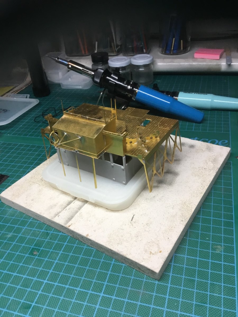
You can see here the type of iron I use; The method is simple enough; Have the joint clean and fixed in place. Load the hot iron with solder. Using a modellers paint brush, paint the joint with liquid flux and immediately offer the loaded iron to the joint. The brass immediately heats up and the solder transfers from the iron to the joint. lastly, avoid any stupid methods of seeing if the iron is hot! Thanks Paul

-
Holding small parts for soldering
Toolmaker replied to BETAQDAVE's topic in Metal Work, Soldering and Metal Fittings
Its Tamiya modellers masking tape. Its fairly low tack and in normal use doesn't leave residue. I think for the most part its about keeping the heat very localised which you can do with a fine nosed soldering iron. I generally use a small radiused nose rather than flat. I hope that helps Paul -
How an 18th Century Sailing Battleship Works
Toolmaker replied to Tossedman's topic in Nautical/Naval History
A very enjoyable watch Thank you Paul -
Holding small parts for soldering
Toolmaker replied to BETAQDAVE's topic in Metal Work, Soldering and Metal Fittings
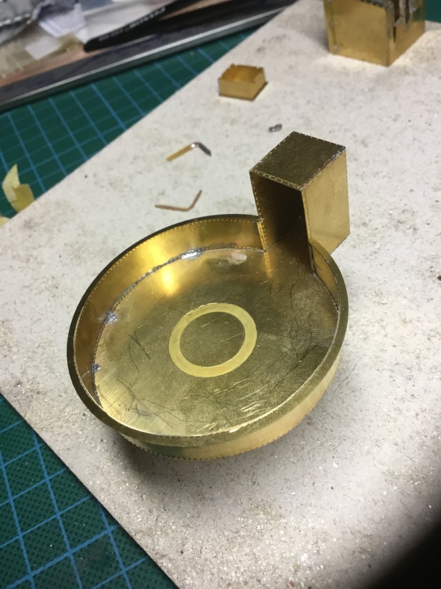
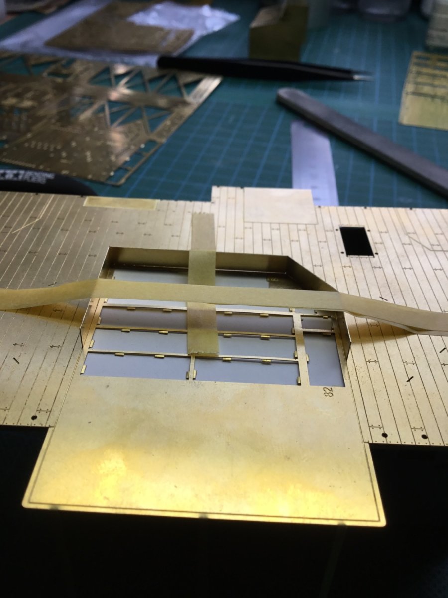
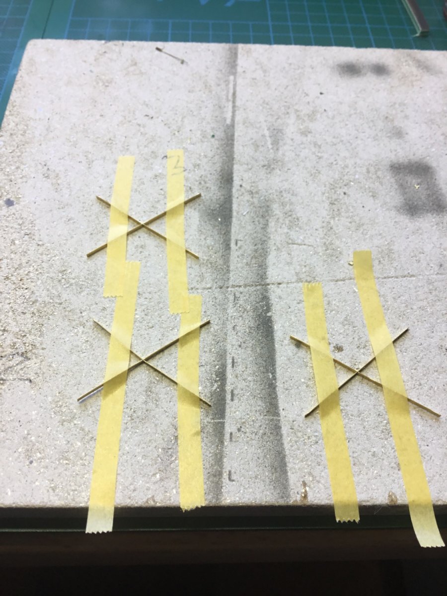
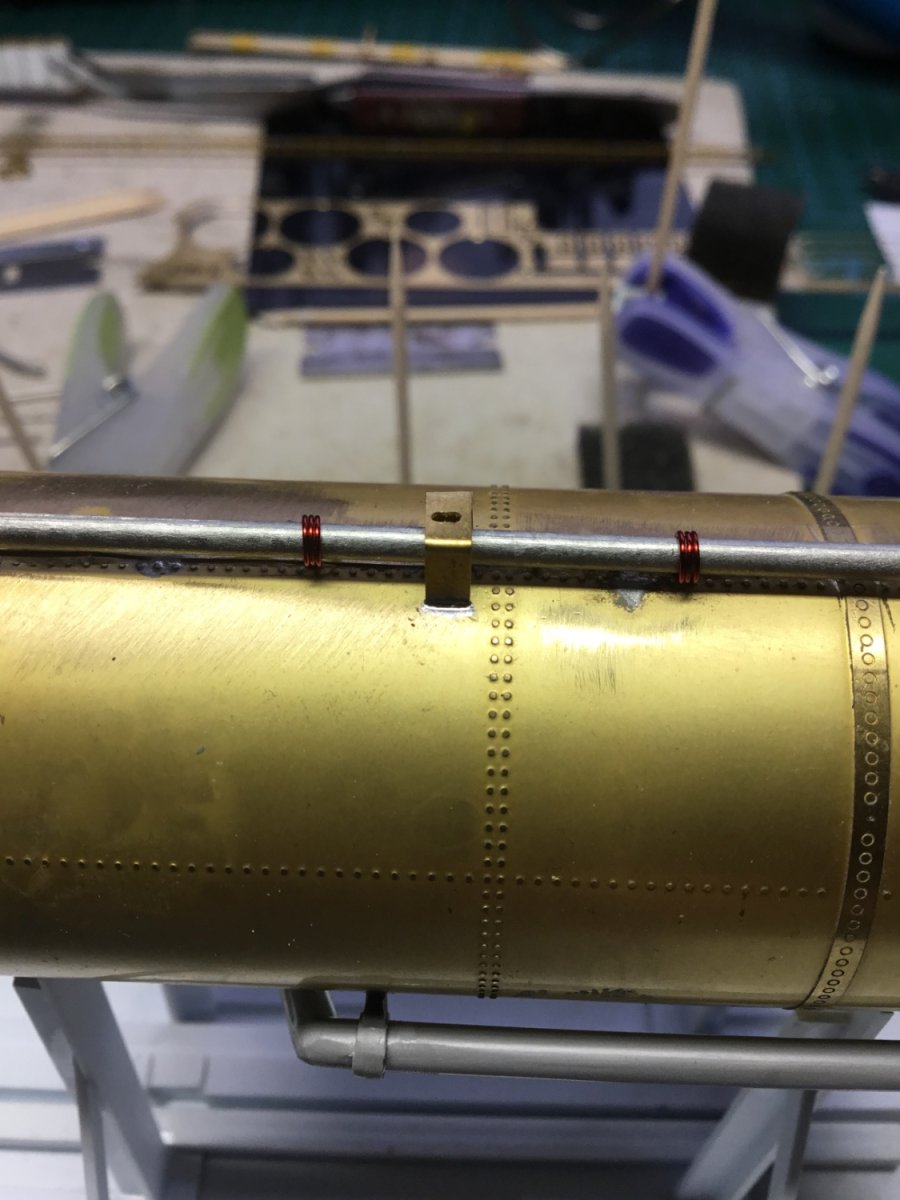
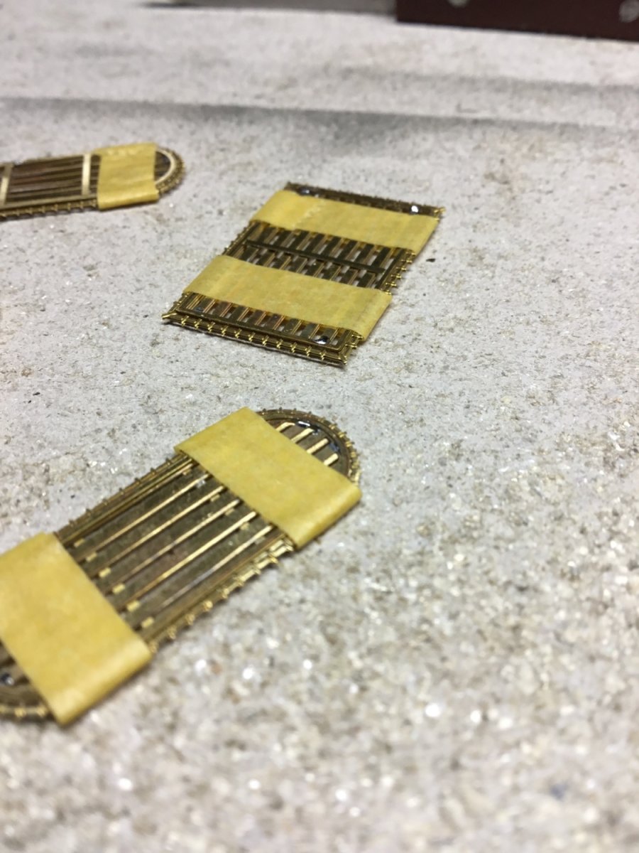
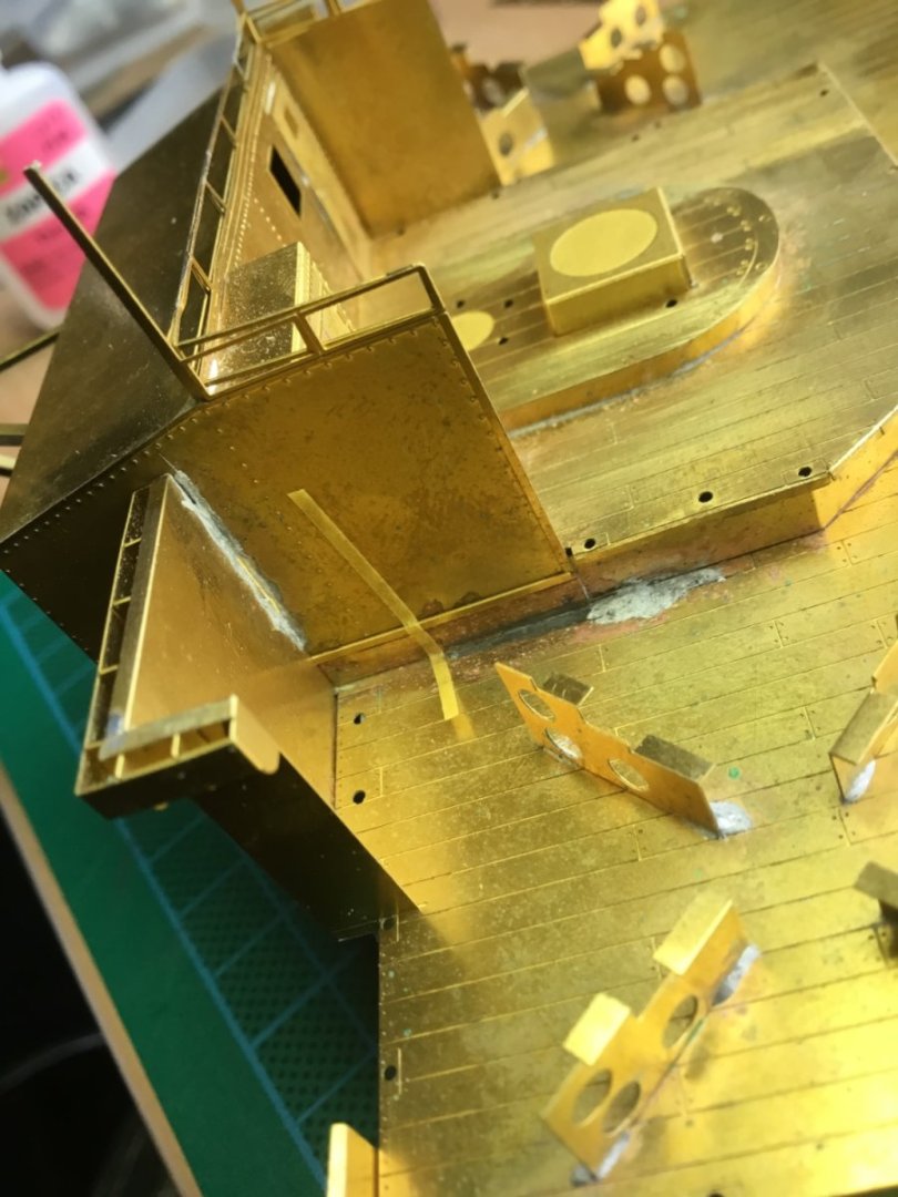
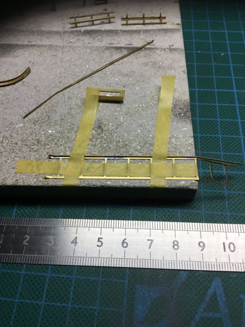
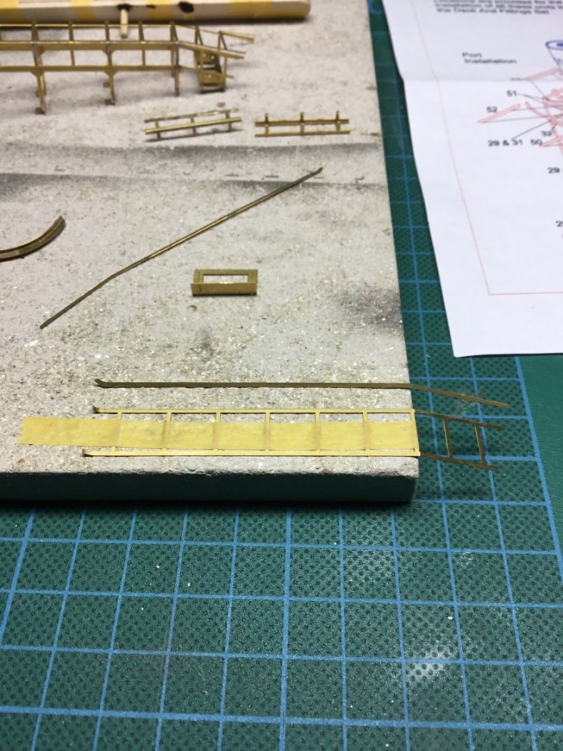
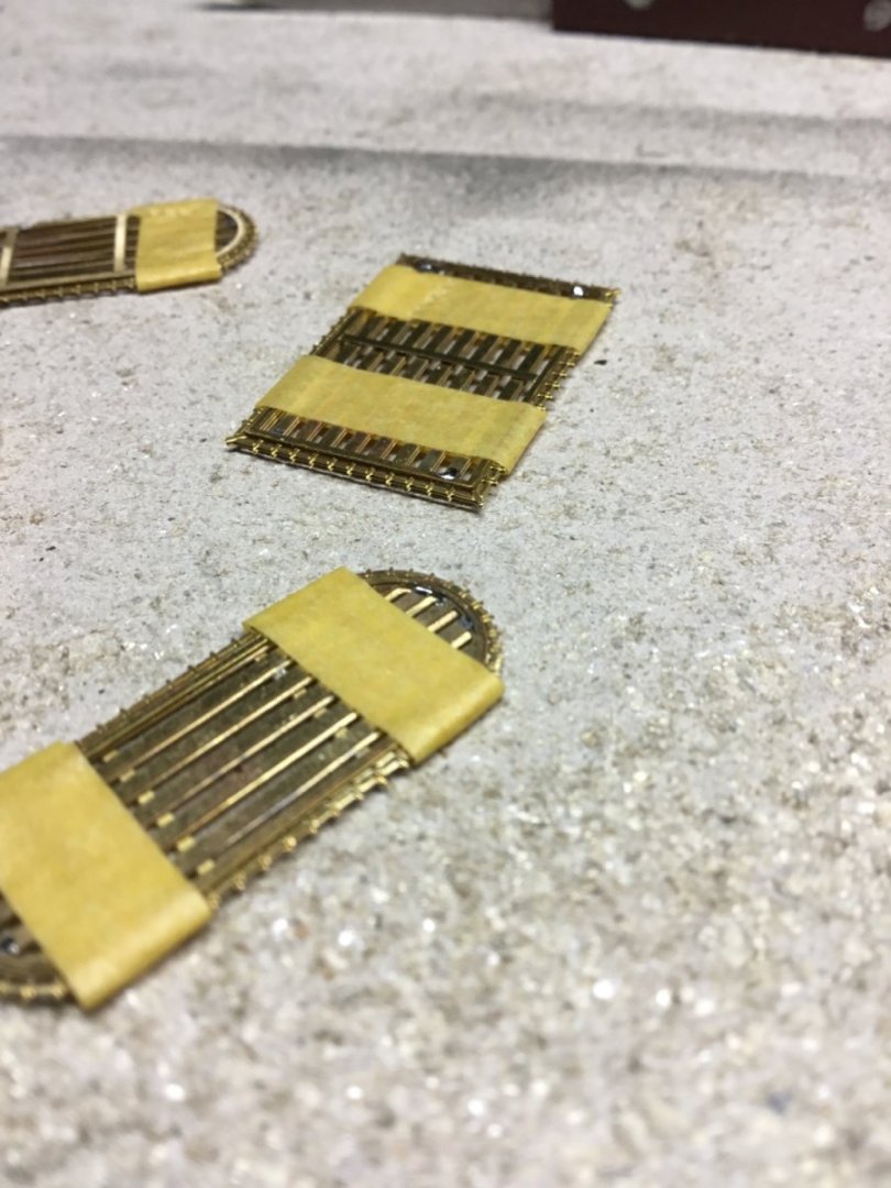
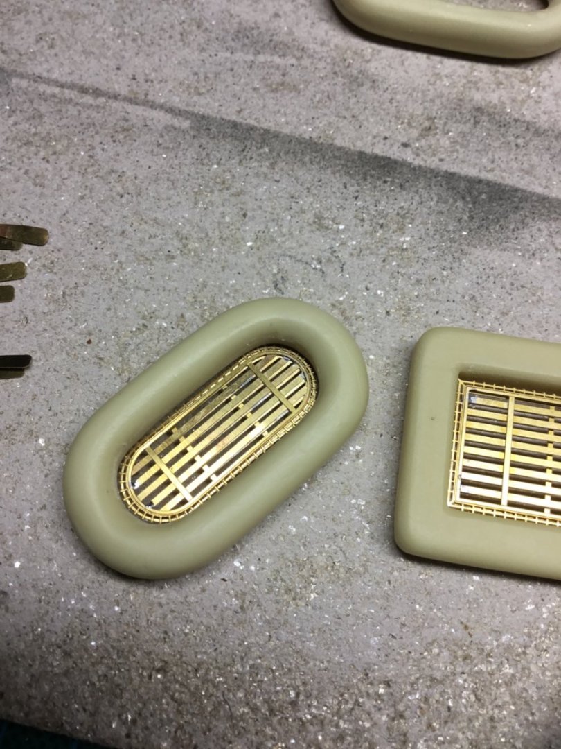
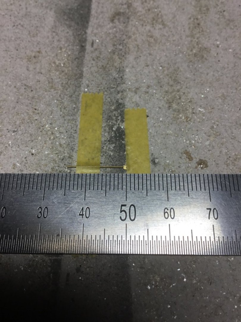
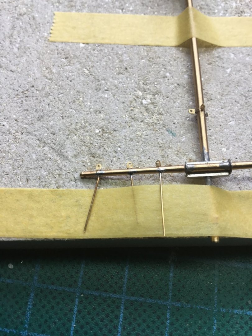
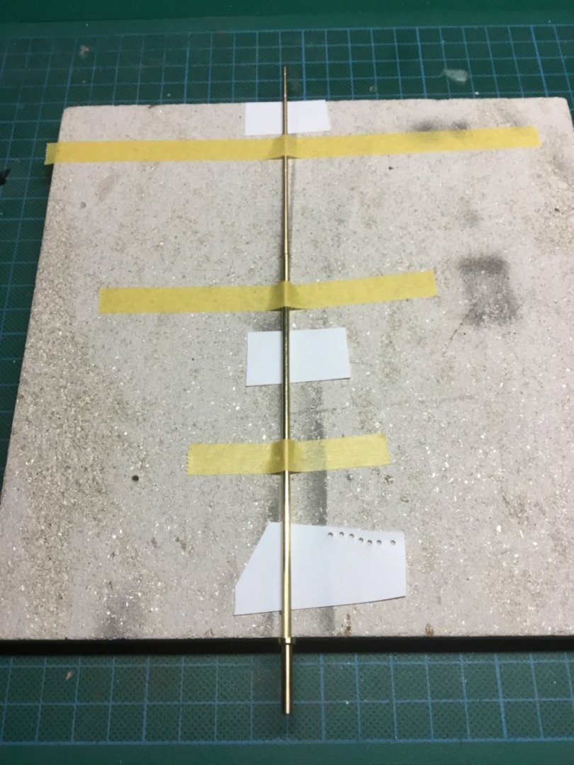
As a follow up to Roger’s post and in agreement with him, I am also a supporter of the soldering iron. My personal preference is a gas powered item. For the most part, ship fittings are lightweight enough to need only soft soldering. My preferred method for holding parts in place is masking tape. That may sound doubtful but it is easier to explain in clear pictures. I hope this is seen as helpful rather than indulgent. Here you can solder between the masking tape and when the tape is removed then solder the rest if you feel it’s necessary. I didn’t. The next two pictures are the all brass bridge. Almost all the parts were soldered whilst held in place with masking tape. Some similar examples Parts were usually taped to a heat resistant tile or held in self grip tweezers. Another example is the Carley floats. Minimum size was also not a barrier. This method of soldering has been discussed before but I thought it worth showing some ideas regarding holding. Thats definitely me done here on soldering 😂. Thank you Paul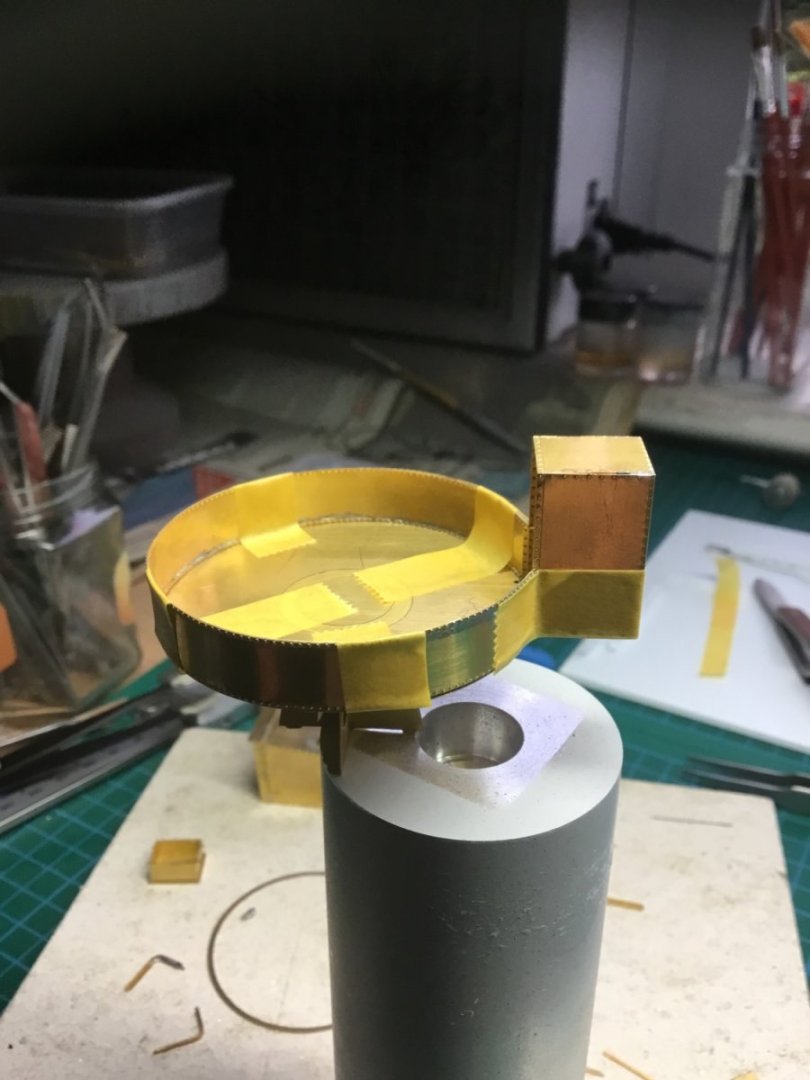


-
Certainly 300 series and 17-4PH(precipitation hardened). I’m sure if you Google it you will find many suppliers for the process. Thank you Paul
-
I’m not sure if I’m missing something here, but I have done a lot of blacking to stainless steel parts.
-
US 6” gun by RGL - FINISHED - Panzer Concepts
Toolmaker replied to RGL's topic in Non-ship/categorised builds
This is great fella’s , your enthusiasm is palpable. It’s always good to see a “all in” approach. Thank Paul