
Toolmaker
-
Posts
237 -
Joined
-
Last visited
Content Type
Profiles
Forums
Gallery
Events
Everything posted by Toolmaker
-
 How I manage to miss these I will never know. Today is the first time I have spotted this and it’s virtually finished. So well done on your latest machine tool. It’s another beaut. You certainly went to town on the base casting and pushed on from there without too many issues. As for the broken tap, cast aluminium can be a little “sticky”. The only advice I can offer is to make sure that your hole at the top of the tapping size or even a little over and use some switch cleaner or paraffin. Another lovely edition to your miniature workshop. I shall try to keep up and catch the start next time. Regards Paul
 -
Size bears no relation to quality
Toolmaker replied to Toolmaker's topic in Modeling tools and Workshop Equipment
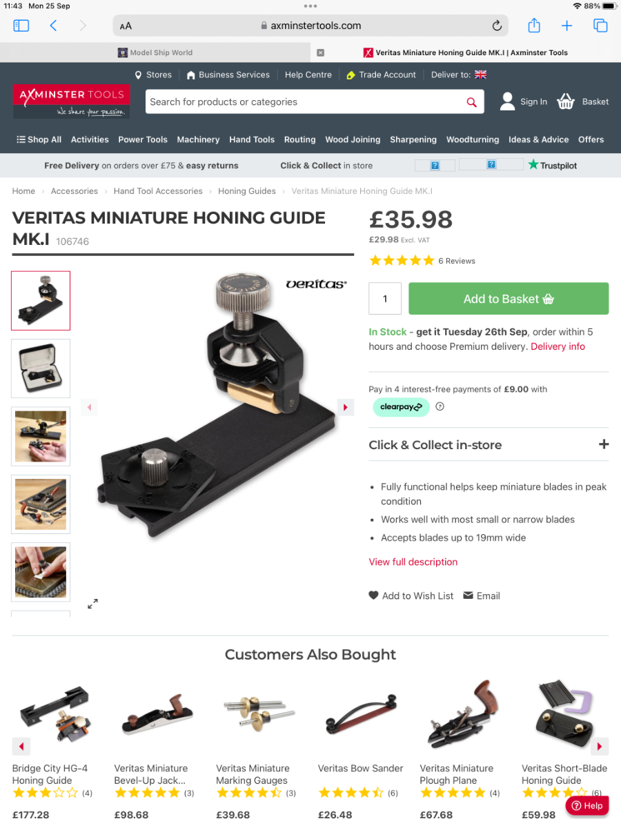
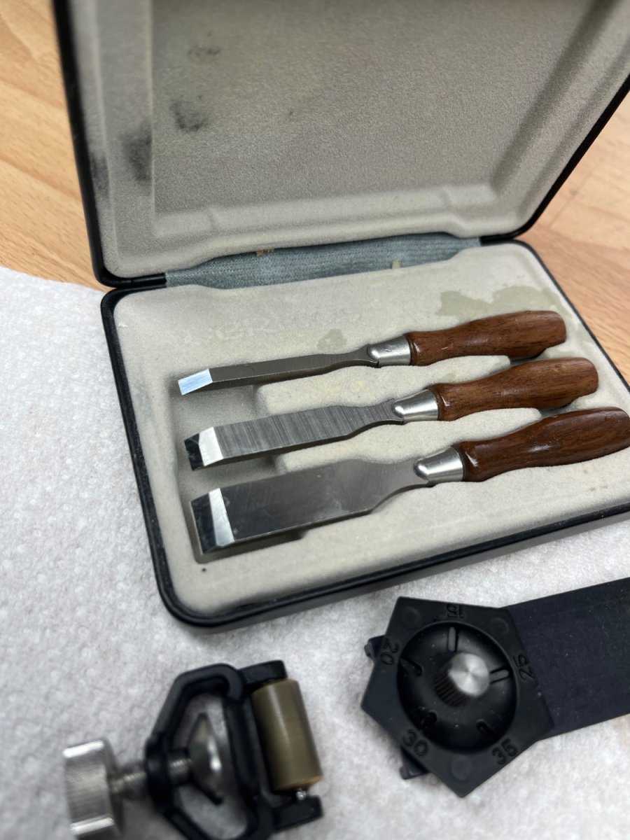
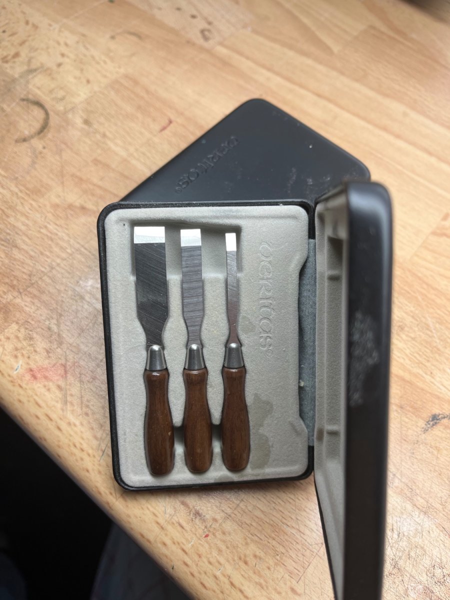
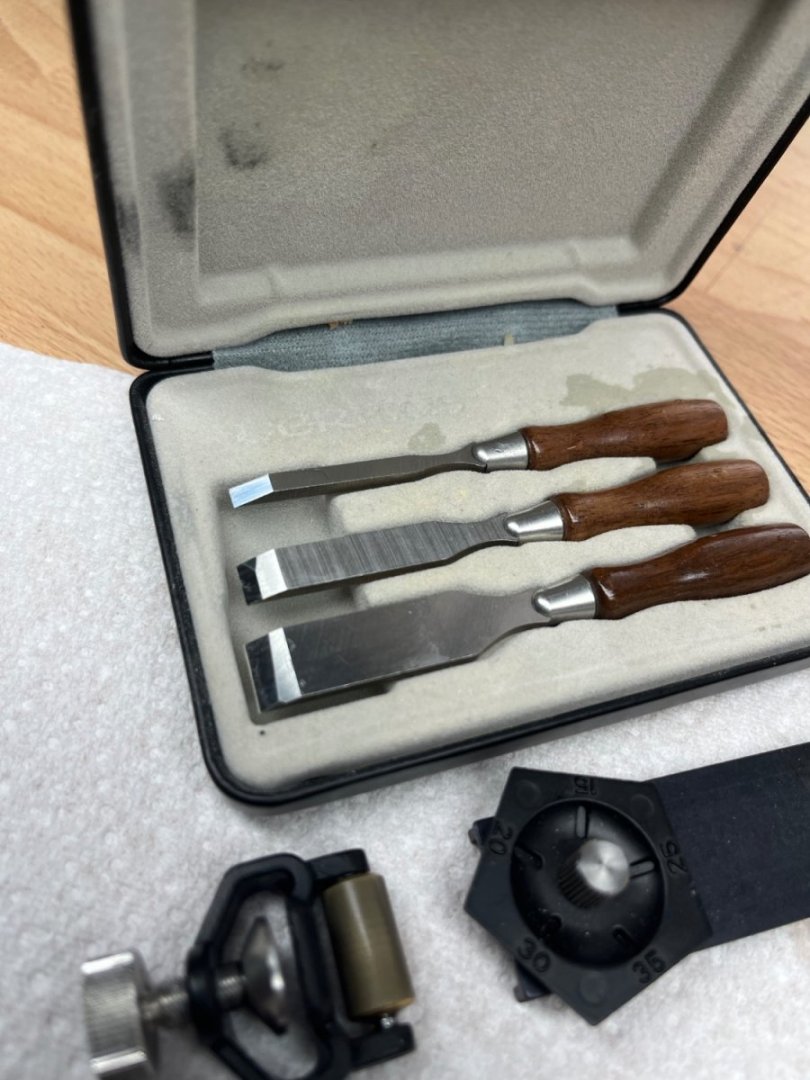
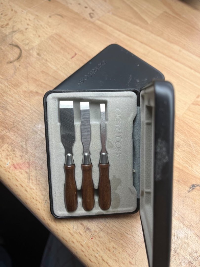
Allan it was Veritas, this is photo from a uk supplier. It’s not a link as they often disappear but it shows what you are looking for. Regards Paul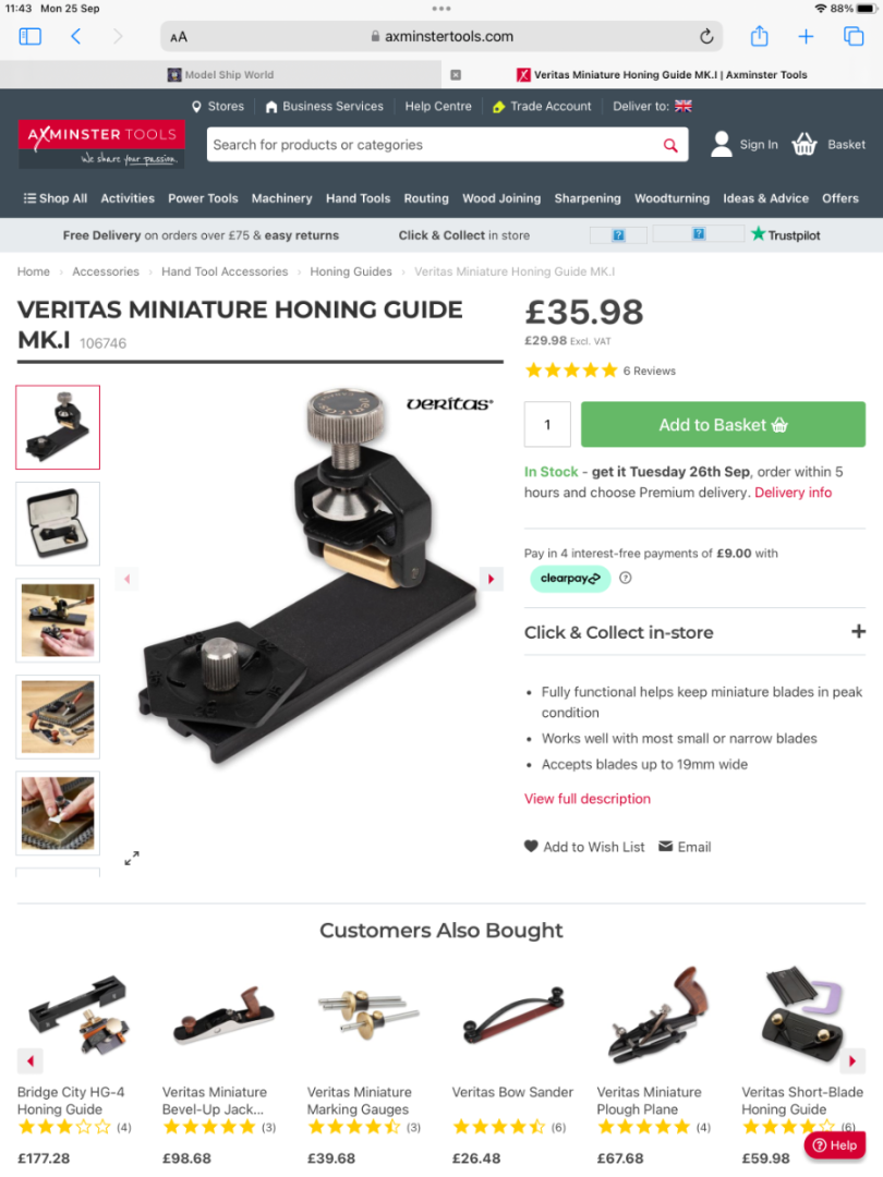
-
Size bears no relation to quality
Toolmaker replied to Toolmaker's topic in Modeling tools and Workshop Equipment
No arguments from me on that point 👍🏼 -
Size bears no relation to quality
Toolmaker replied to Toolmaker's topic in Modeling tools and Workshop Equipment
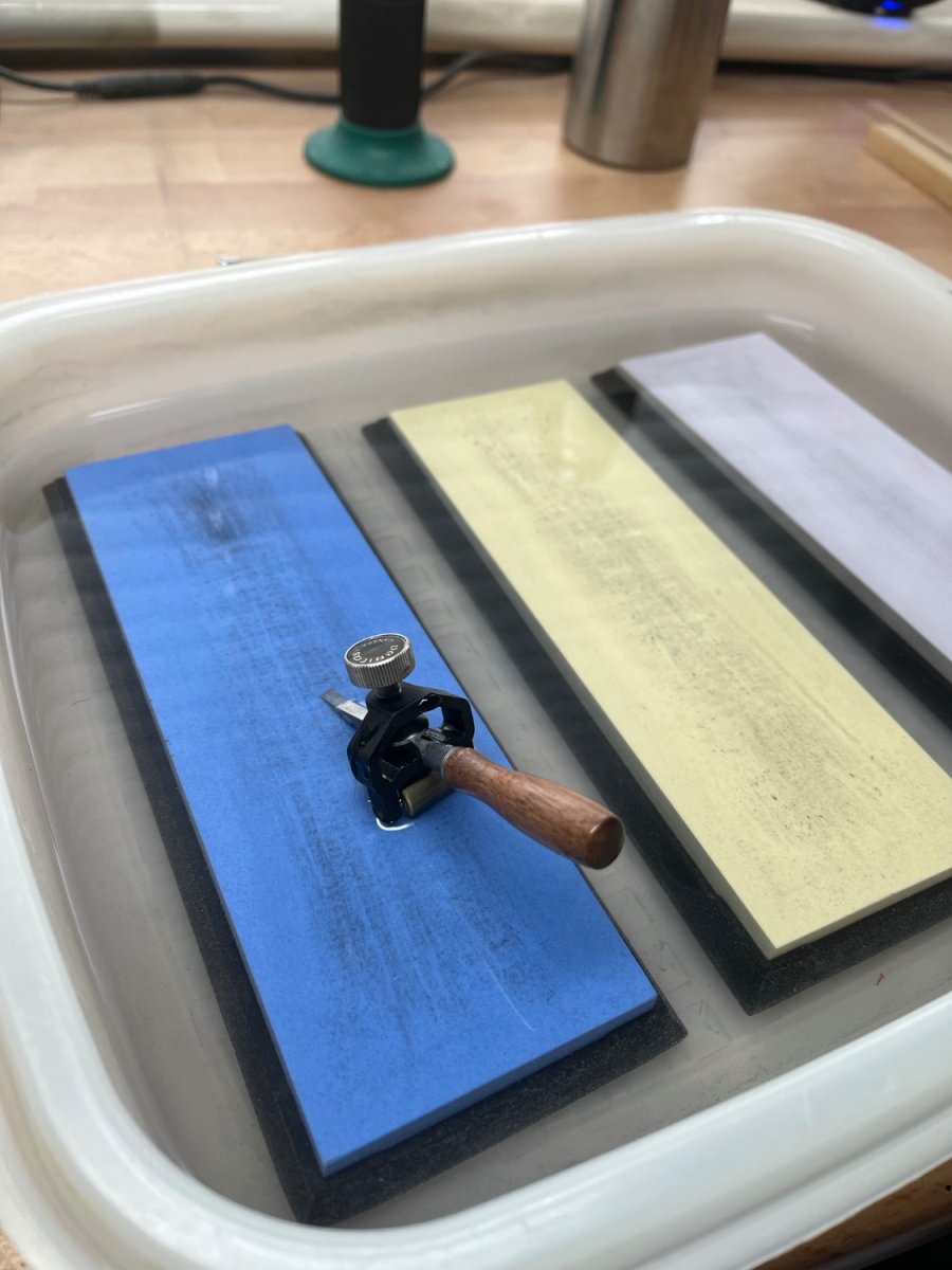
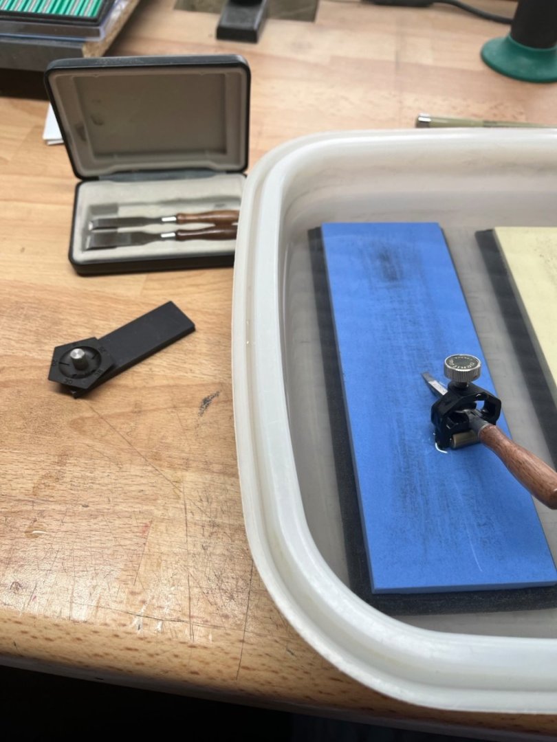
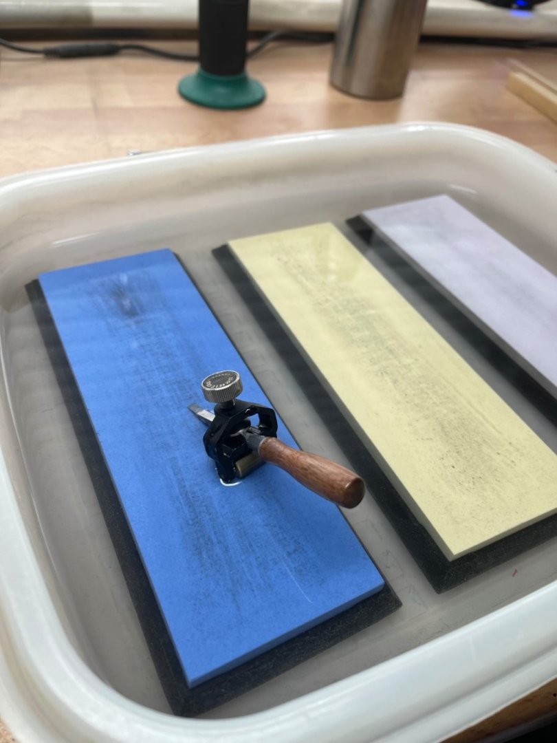
Serious input, thanks. I have to say that these little chisels hold a great edge for weeks/months from a single sharpening. I hope I’m not going to disappoint here, but the holder is a veritas model if memory serves me right. Tighten it as hard as possible and then sharpen from that position. Don’t remove until done. -
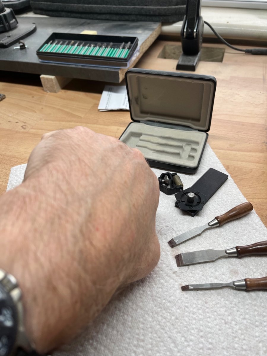
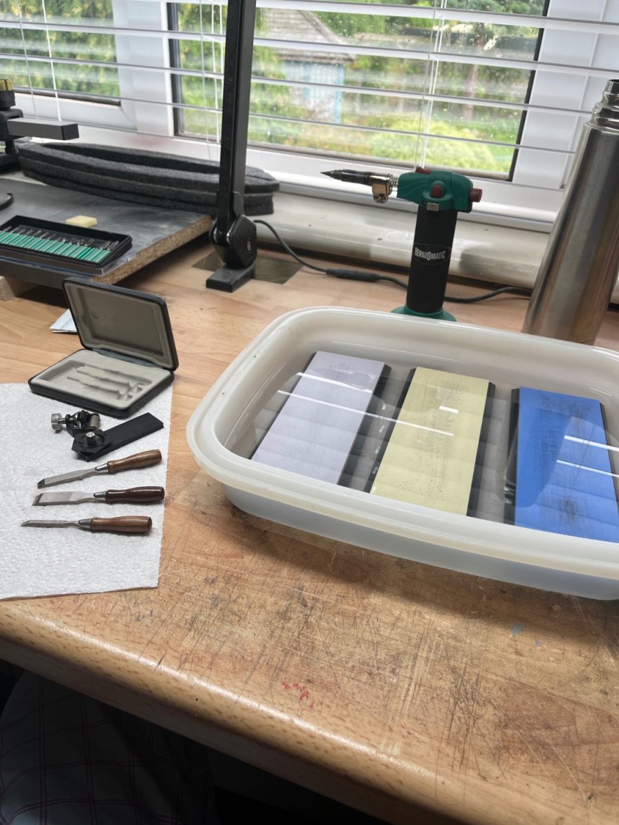
I’ve just sharpened my miniature chisels for the second time I bought these with a large dose of scepticism as apart from 4 years rearing chickens I have spent all my professional life in the pursuit of the best cutting tools. I’m in my mid sixties now, so that’s been a while. As expected, when they arrived they were not finished when it came to edge confirmation. I spent the best part of a day getting them to where I thought they could best perform. I have just completed the hull on the Syren model HMS Cheerful which has been done in Costello Boxwood. These chisels have been exemplary. I can happily state that the whole process would have been much more difficult without them. Those previous 2 pictures are trying to show that the steel used is good enough to take a “shaving” edge. I know it’s a little bizarre to shave your own hand and I accept no responsibility for any of you attempting similar, but it does prove a point. This is a simple set up using 600, 1000 and 3000 grit stones in a sunken bath of water. After completing a hull, it took less than an hour to reinstate a good edge on all three chisels. Its not easy to get a good shot of the edge with a phone camera. Get in touch if I can help with your chisel sharpening challenge. I’m sure you recognise these chisels and I have no relationship to the manufacturer. They are however the real deal, albeit in miniature. Cheers folks, I hope that might be useful. regards Paul


-
Hi Rob, I’ve not commented on your more recent builds, but I have enjoyed following along immensely. I feel your pain regarding rigging, or in fact any other aspect of modelling that we might struggle with to match our peers. To that end, I have a good friend who is a very accomplished modeller, he is an IPMS Championship winner in the UK and his work is well respected in aircraft modelling magazines. He recently told me how he would “love” to copy my model ship woodwork, but felt he was rubbish at woodwork. Now I know he would be fantastic at doing wooden ship models, (eventually), but of course the “apprenticeship is still x number of years”, and that won’t be full of walk in the park fun. Myself, I have been a confident airbrusher, hey I could spray, clean the airbrush and spray again six time an hour. I used to solder 0.5mm brass for fun, but for the past 3 years I have struggled with wood ship building. Thankfully I am improving (I realise that’s only my opinion) and I am committed to this part of the hobby as I have sold all my plastic kits. I think the upshot is that some of the model making skills take years to master and like with anything if you don’t keep updating those skills you will lose them. “Jack of all trades, master of none” was a saying from my youth and it still stands today. I think eventually you will probably decide to focus more on what you enjoy, which of course is obvious as long as it remains a hobby. Aside from the modelling, I enjoy your open approach and collective sharing. Thank you. Cheers bud Regards Paul
-
Mini self contained airbrush
Toolmaker replied to Bill Hudson's topic in Modeling tools and Workshop Equipment
Am I wrong in thinking you would have continually changing pressure with that style. -
searchig
Toolmaker replied to Pirate's topic in Using the MSW forum - **NO MODELING CONTENT IN THIS SUB-FORUM**
Top link in lists of kits. Top link again https://modelshipworld.com/forum/150-index-of-all-kits-by-brand-and-subject/ Top link again pick the date 1851-1900👍🏼 Scroll down and you find around 50 build logs for your requested subject -
Would you buy pre-owned wooden kits?
Toolmaker replied to Frank Burroughs's topic in Wood ship model kits
Hey Frank, this post will be substantially shorter than the previous. Don't overthink it mate, grab the Fife or similar. There is no wood to cut, there is no need for the garage. The painted hull is done with acrylics so no ventilation. Sanding is maybe 3 or 4 hours over the complete build, so half a day outside is the total demand. Think easy. I do everything in a spare bedroom. -
Would you buy pre-owned wooden kits?
Toolmaker replied to Frank Burroughs's topic in Wood ship model kits
Hi Frank, it’s good to talk. I’ll start by saying you always have to plough your own furrow, and what people write here is the advice they can offer after ploughing their own. The beauty is, you get lots of it and then get to pick what to take on board (see what I did there, humour that was). My only qualifications are the same as others, just what I learnt so far and it’s not that much to be fair. I previously did plenty of plastic modelling reaching an ok standard. I even managed a mention in the forward of a ship modelling book for contribution, Yay! My biggest effort was 2000 hours spent on building a Flower Class Corvette. That said, a couple or more years ago I sold all my accumulated plastic kits, around 60, and embarked on wooden ship building. For context, I’m an oldish bloke with dozens of years in mechanical engineering, good with my hands and tools and comfortable around plans and measurements (that’s my resume/CV over). Here are my thoughts on your original post. First, I thought your opening line was classic modellers talk and very funny. Advice and my own journey. Buy the Vanguard Fife kit. Even if you didn’t have any tools prior, you could buy everything needed for less than a large 1/200 scale plastic kit. Straight edge, scalpel, wood glue, clamps and sanding sticks/paper is all that’s needed. An electric drill is handy to taper the mast, but not necessary. It’s a simple hull shape but offering all the opportunities to learn good planking techniques. A kit even as basic as this (don’t mistake basic for poor quality) will likely take a number of months to complete. By the end you will know if you wish to continue with wooden ship building without great expense. Yes, this was my first wood build and yes I did have a lot to learn and yes I did want more. Learning from my previous “eyes bigger than stomach” syndrome I went for the Vanguard HMS Alert. Another great quality kit that would offer me a (slightly) more complex hull shape and a goodly starter complement of rigging. Man, I was going to need to up my tool chest for this one. The Amati keel clamp was more excuse than absolutely necessary but acquired nevertheless, along with a palm plane and a hair dryer(travel iron is another option). Some months later I was again on the lookout for the next step as I saw it. Syren Medway Longboat. Large scale demanding greater accuracy. For the third time in a row I had chosen a fabulous kit. This route exposes you as there can be no blame laid on the kit for any failure. That’s not quite how I saw it but more that I was giving myself the best chance of success. The longboat was another leap in acquiring skills needed for my ultimate builds. It was only after this that I flicked the switch on tool purchase. A saw and sander imported from the US, a US made milling machine and a German dust extractor (ha, and me a British engineer). I have now embarked on building two Syren models. HMS Cheerful and HMS Winchelsea. I call them my legacy builds as I feel my plastic ships will be heading for the rubbish bin when I’m gone but the kids will probably keep the wooden stuff. I have purchased the kit components from Syren for both and the wood has come from Vahur at Hobbymill. What a great guy he is. He cut the Winchelsea planks for me but I’m milling all my own for Cheerful. These two builds will take 5 to 6 years to complete which is akin to me saying don’t acquire a stash of wooden kits as they take such a long time to build. Well that’s as long winded as I have ever been and tells you my route from plastic to wood ship building. Basically don’t acquire more than you need and get going on the skill building. Give yourself the best chance by using a good kit. If you are specific subject driven then this is more difficult but it is easier to acquire the skills with good materials. Lastly, I have always been both impressed and grateful by the effort that Bob Cleek gives in his responses to people’s questions on this forum. His commitment to full and rational replies was my inspiration for this one. Cheers Bob and good luck Frank regards Paul -
Is it the red or the gloss that you don’t like? If it’s the gloss then try spraying on a dull coat (clear matt varnish).
-
Late advice might be worse than none, but it might help next time. I have built a number of tanks including this kit and find some items are more suited to being painted before attaching. On the Whippet build I painted the exhausts, the machine guns with mounts, the towing cables and the tracks prior to fixing them in place. Fixing hem was after the base colour had been applied to the main tank body. it’s a great kit and lends itself to some nice weathering. Good luck with the build. Regards Paul
-
Thoughtful and tidy as ever Mark, very nice work mate
-
Hi Richard, I have been off piste for a few months and sadly missed much of this build. That said and having spent a couple of hours catching up with your efforts I gladly offer a huge thumbs up. The finished job looks fab. Paul
-
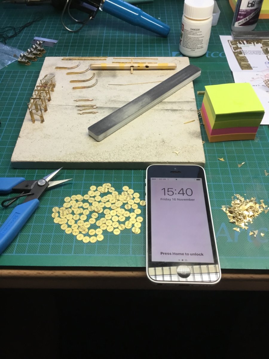
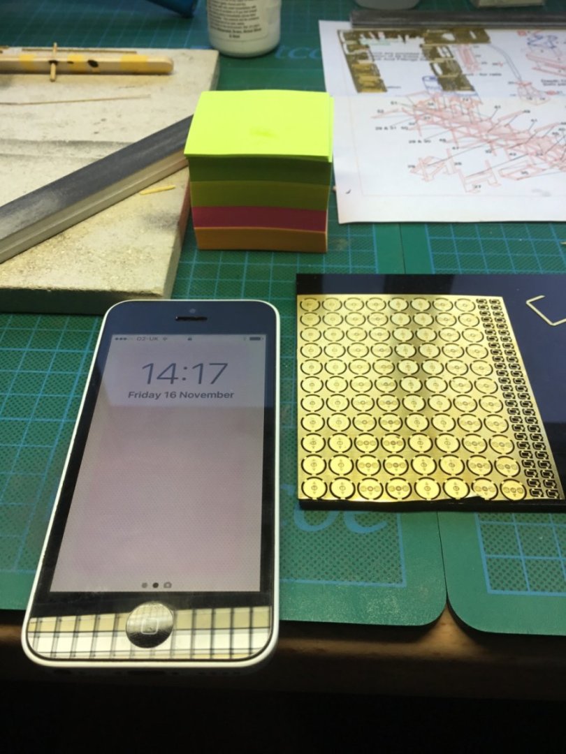
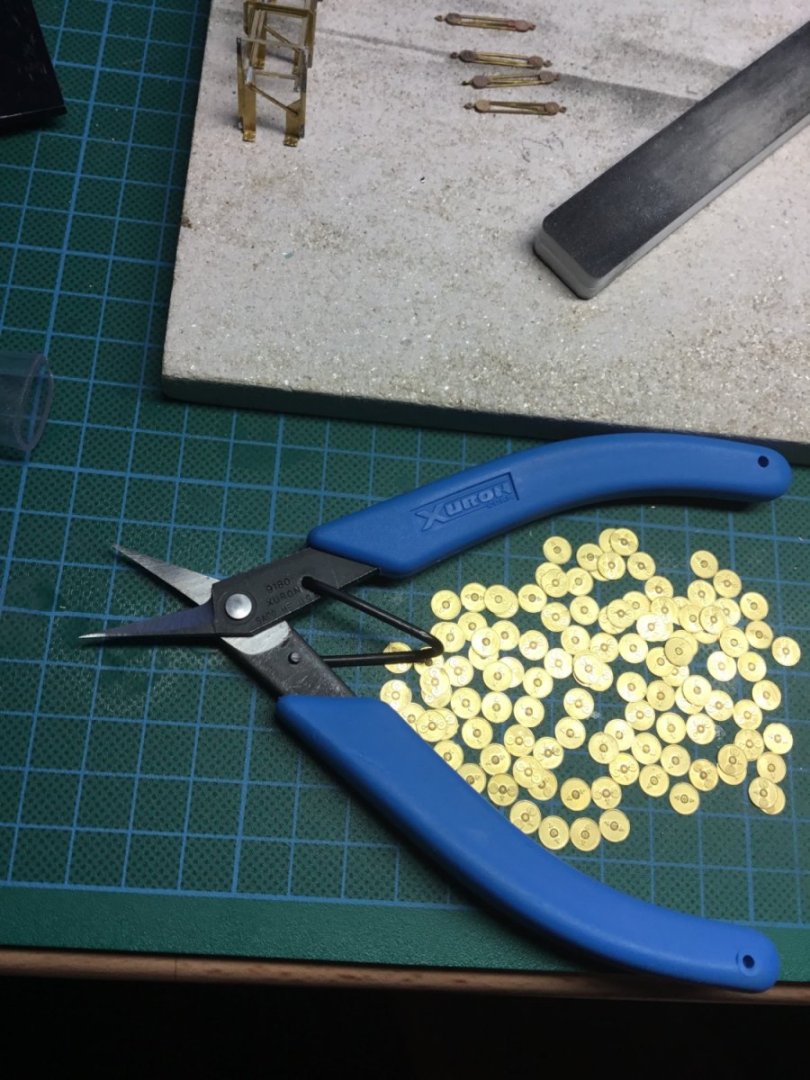
“A picture paints a thousand words” apparently. So here is a quick 3k words. Hope it helps Excuse the phone, it’s a few years ago A scalpel just wasn’t appropriate on this occasion great cutters, really worth the money if your going to be doing a lot of photo etch. Good luck Paul

-
I’m not sure on the protocol here but as somebody who knew Kev I thought I should share the sad news that Kev passed away yesterday morning. Having spent time with him over recent years I always found him to be great company and I shall miss not listening to his sea fairing tales. Although not seen so much here as he was just a recent convert, he was a fabulous show winning modeller. RIP Kev.
-
Where can I get small grommets?
Toolmaker replied to Seamus107's topic in Masting, rigging and sails
I’m unsure if any kind of self manufacture is an option. This picture comes from Chuck at Syren and shows his simple method using small pieces of brass tube. Other than sawing the pieces no other machining is required. He just swages the end with a tapered punch and a hammer. I hope that is useful Thanks Paul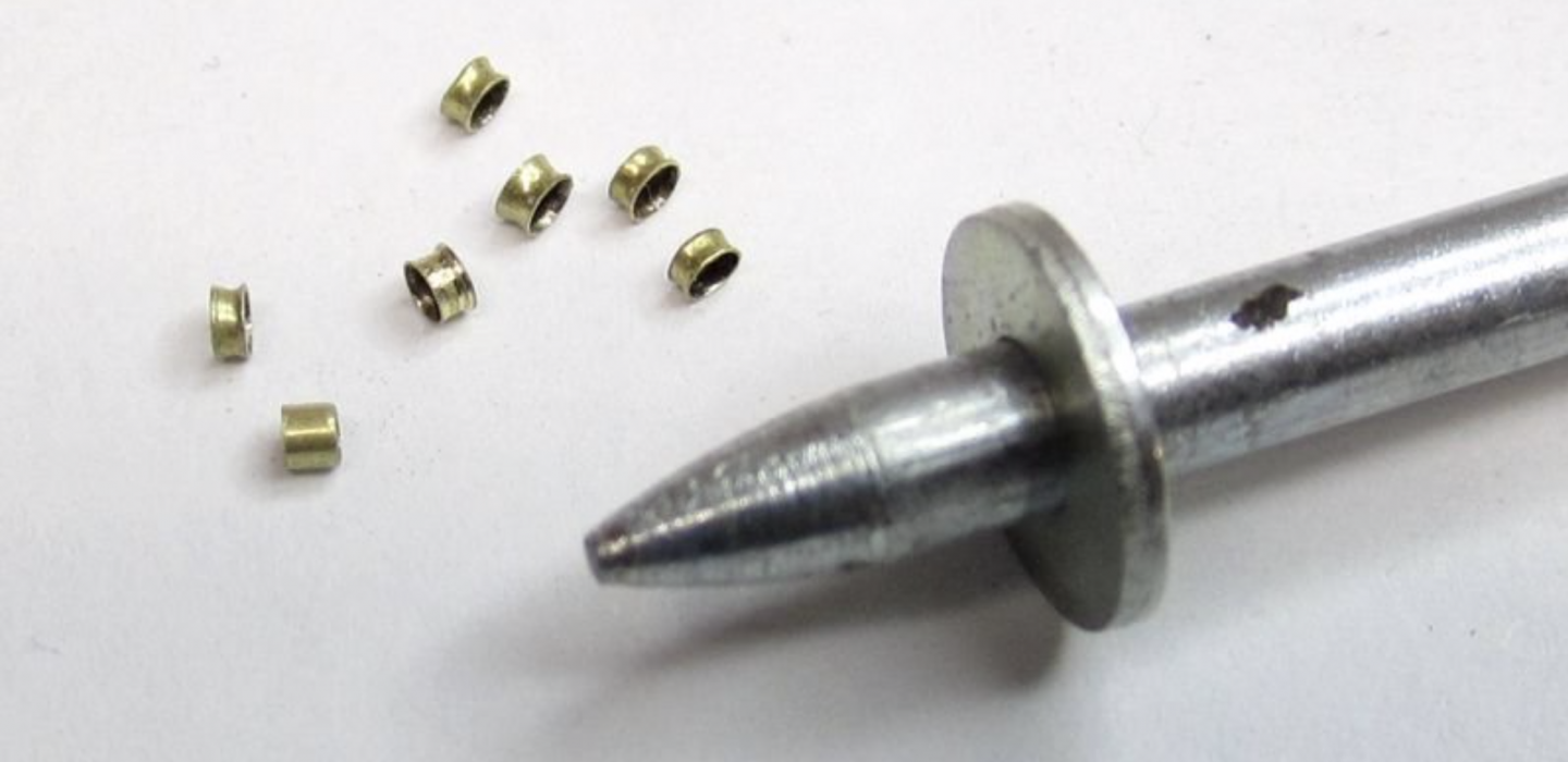
-
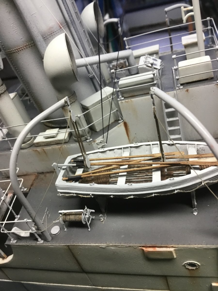
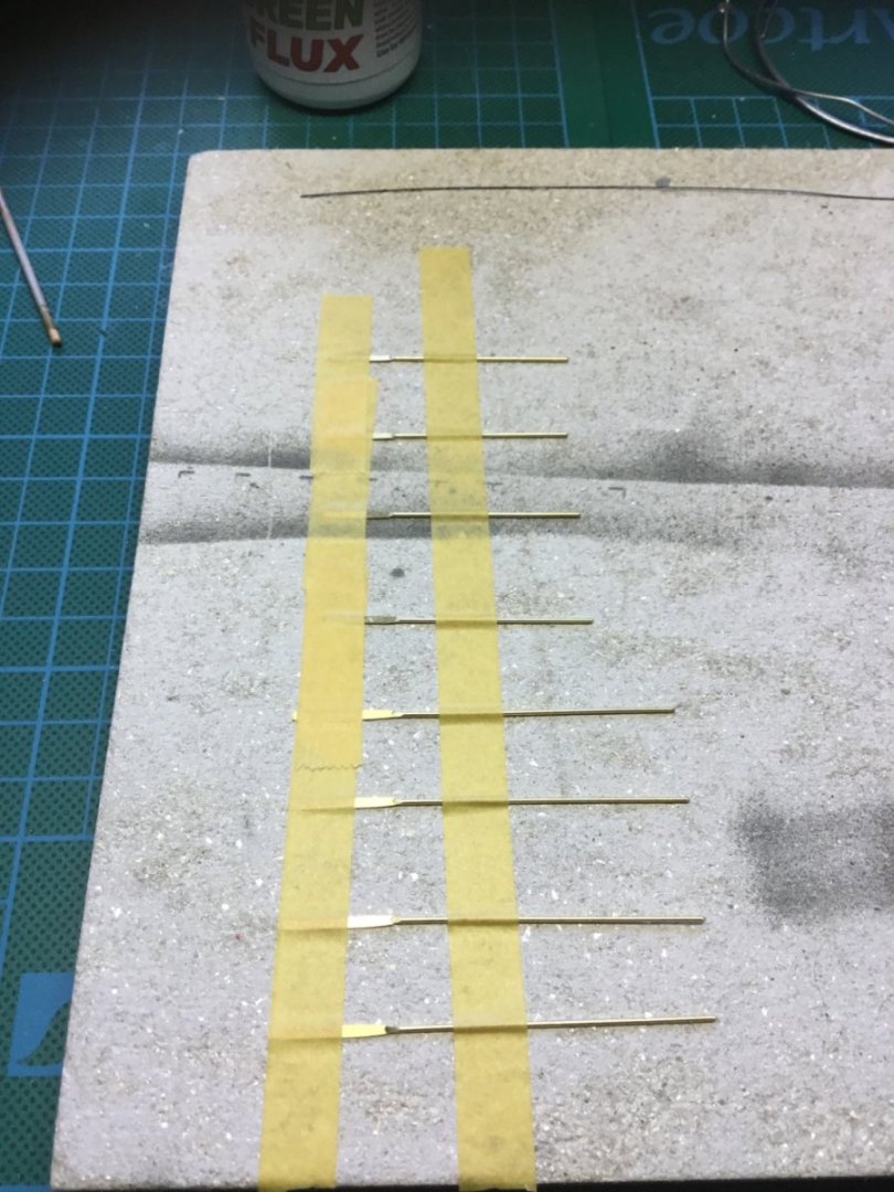
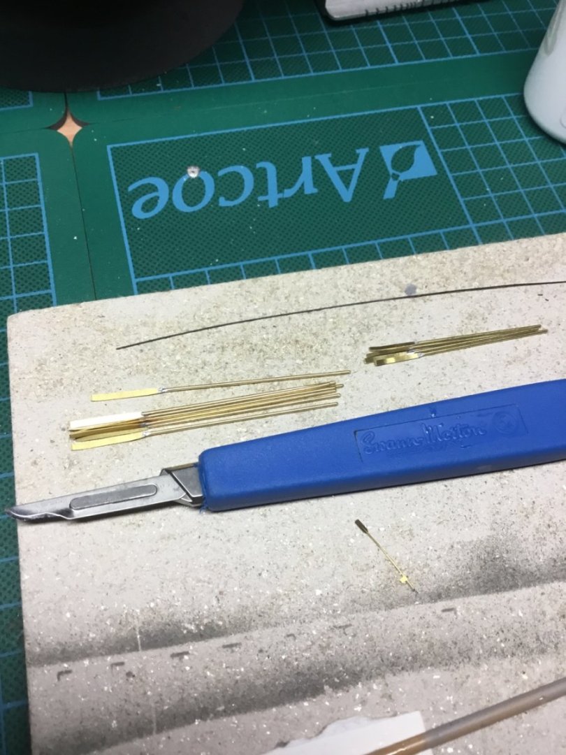
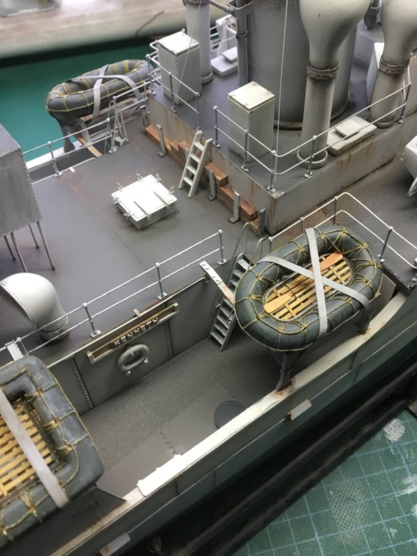
I can endorse this method. I used it for various oars on a 1/72 scale WW2 era vessel. The pictures will show all but if further details are wanted, just ask. Hope that is useful. Cheers Paul

- 58 replies
-
- 10
-

-

-
Yes, you could bore soft jaws on the lathe.
-
On the subject of turning long thin diameters, did you ever use roller boxes for turning?
-
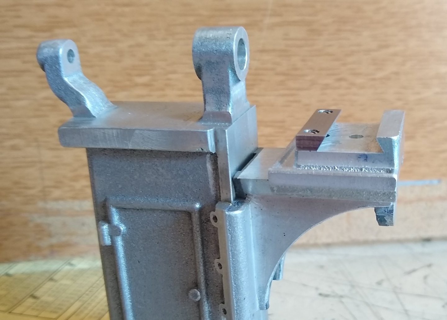
Hi Richard, It seems I have been asleep on watch and have missed a couple of updates. It’s all moving along and looking well. That tapered pin is a sneaky little widget. It looks simple enough until you come to execute. I looked at the drawings that showed it and the picture of the assembled model, and in both it looks like the hole in the end is not central. Am I seeing that correctly? This is my offering; Al/Al round bar, drill and taper ream so your taper pin sits under flush by a couple of mm. So longer than the pin and the pin is fully inside. Mill the al/al bar to give 2 parallel sides or 4 if you prefer. At the mid point drill and tap through to the taper hole. This s for a grub screw. 2mm or perhaps 3mm will be fine. Locate the taper pin in the al/al fixture with a bit of force, tighten the grub screw and Mill the ends of the al/al flush to the pin. Stand in vice with the bottom on a parallel which adds further security for the pin not pushing out and do your work. Turn over and repeat. Remove pin and dress you grub screw indent. It won’t be seen on assembly. This all seems long winded, but 1 offs can be that way. Thank you Paul
-
Seriously nice work on show there Mark. A heady mix of carpentry and wood engineering which you have combined perfectly. Cheers Paul
-
Good thinking, it never entered my head that someone might try and make this without buying the plans. More fool them I say. Regarding the nut/dovetail thing; I was suggesting you screw and dowel the steel dovetail on to the cast aluminium part, then machine the complete dovetail to clean up true, parallel etc. Then the steel piece can be taken off/put back on at your leisure. The dowels would always maintain its positional accuracy. Two 1.5mm holes should suffice. Every possibility you and I are going around in circles here, but that’s ok Regards Paul
-
You and me both Richard, unfortunately your the only one with the plans, hahaha Due to my current strong pain killers I am yet to decide if we are at cross purpose on my latest convoluted plan. Why is it you feel the feed nut needs to be in place. Is it for alignment? I’m maybe thinking it could sit in a slot as opposed to a hole…….but then again it could be the drugs! Best regards as always and if I become annoying just shoo me away. Paul
-
Hi Richard, I think I am up to speed now. You were noting that the separate dovetail piece had to be so to enable access to the partially hidden hole in the above picture, which takes the knee nut. Agreed. Being simple, I thought you were concerned about reaching the steel dovetail screws and pointed out that you need to turn the saddle 180 deg in the above picture, duh 🙄 Assembly is fasten the saddle nut in place, slide saddle onto knee whilst locating knee nut. Fasten knee nut with cap head. Add part four and hold in place against fixed dovetail. Offer up separate dovetail slide slide and fit for play and then install a dowel. I don’t think 1 dowel is good engineering as the part could rotate on that to the extent of the play in the screw threads holding the dovetail piece. What does part 4 look like? Do you still need to machine the dovetail in that? You could dowel the piece on now and re machine the complete saddle dovetail knowing that in the doweled position it is all nice and parallel. Then machine part 4 to suit. You will have to be able to remove the dowels for assembly. There! Clear as mud! Enjoy Paul