
Toolmaker
-
Posts
240 -
Joined
-
Last visited
Content Type
Profiles
Forums
Gallery
Events
Everything posted by Toolmaker
-

US 6” gun by RGL - FINISHED - Panzer Concepts
Toolmaker replied to RGL's topic in Non-ship/categorised builds
This is great fella’s , your enthusiasm is palpable. It’s always good to see a “all in” approach. Thank Paul -
Looking at your gallery images it’s certainly something I would like to see more of. Thank you Paul
-
Thank you for the interest shown and taking the time to comment. I’m sure you’re correct that this only worked due to the reasonably simple hull shape. The appeal for me was that I was able to have full length strakes over the complete hull. The last strake ended up varying between 2.2mm and 3.5mm so not much lost over the hull. I only measured on one side, over assuming, however I was lucky that it came out fairly even. After I had shaped each piece and bevelled the edge, I did pre-shape them. It’s a very neat kit. I thoroughly enjoyed it. Thank you. I intend to follow your lead. I got away with my cheap fix but intend to up my game going forward. Thanks for commenting, it’s appreciated. Thanks Tim, I’m sure you will do a great job on your upcoming build. If you do intend to try the route I took, here are some notes I made at the time. The shaping of the planks, even as a bunch of 10 brings its own if’s and but’s; Measure the widths of your planks and bundle them into +/- 0.05. My 4.1mm average width became 4.0mm on one batch. My Alert planks varied by 0.3mm over the lot. Choose the best side of each plank, when you stack them for profiling you will want 5 with the best side facing you and 5 with it facing away. Port and Starboard become a mirror image. On the reverse of each plank Mark the bottom as it’s surprisingly difficult to tell which edge you have profiled once they are all separated. Mark m/s on each plank as everything is taken from there. Watch out for losing that mark when you soak the plank😂 The front taper lends itself to using a plane. As a batch your stack is now about 12mm wide. The v shaped in the plank towards the stern is more problematic. Now if only I had a laser cutter and some nice sheets of pear wood! I found I approximately shaped the planks as a batch and then finished each individually. I needed to taper the front end of each plank to fit in the keel slot. It’s just a couple of millimetres. Do it on the back of the plank. This and the upper edge bevel should be done before bending. It can be done after should you forget but it’s a lot harder to bevel a compound curved edge. All the best Paul

-
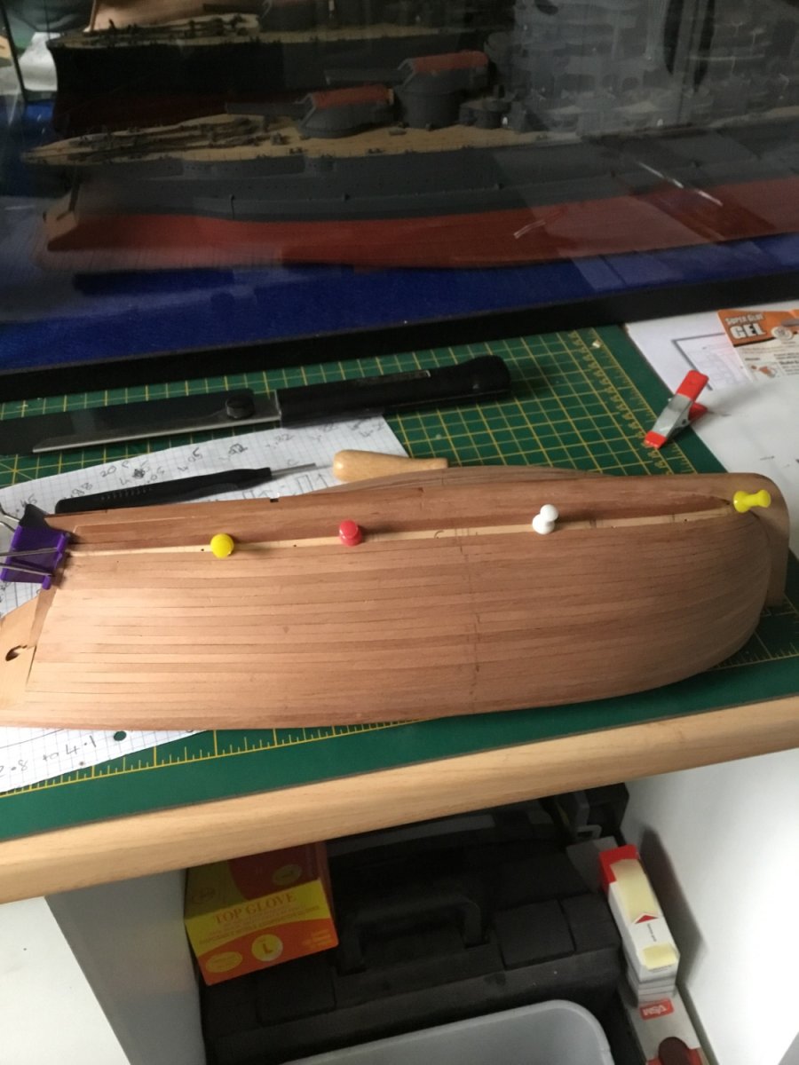
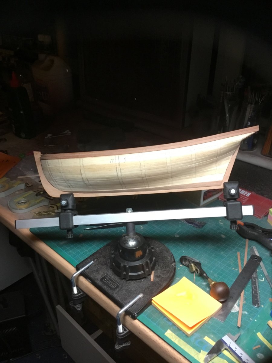
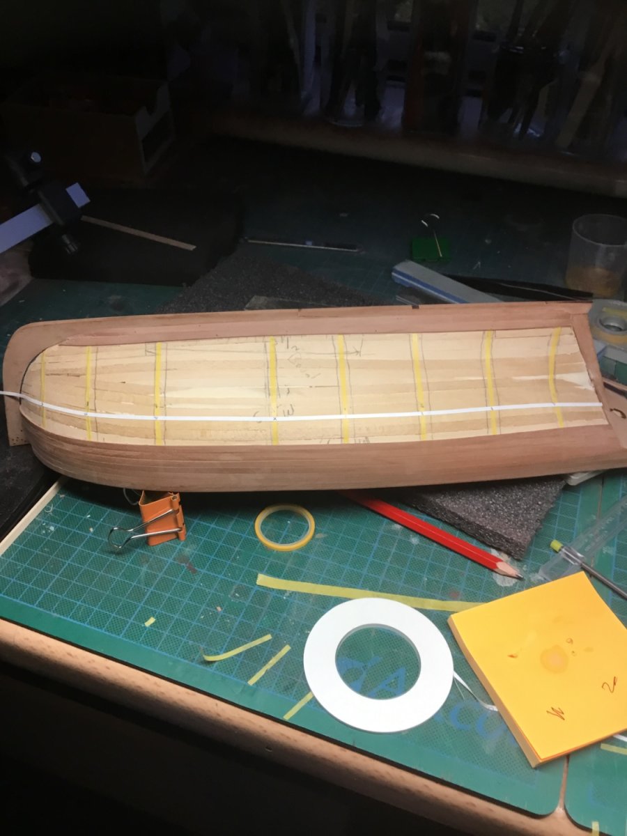
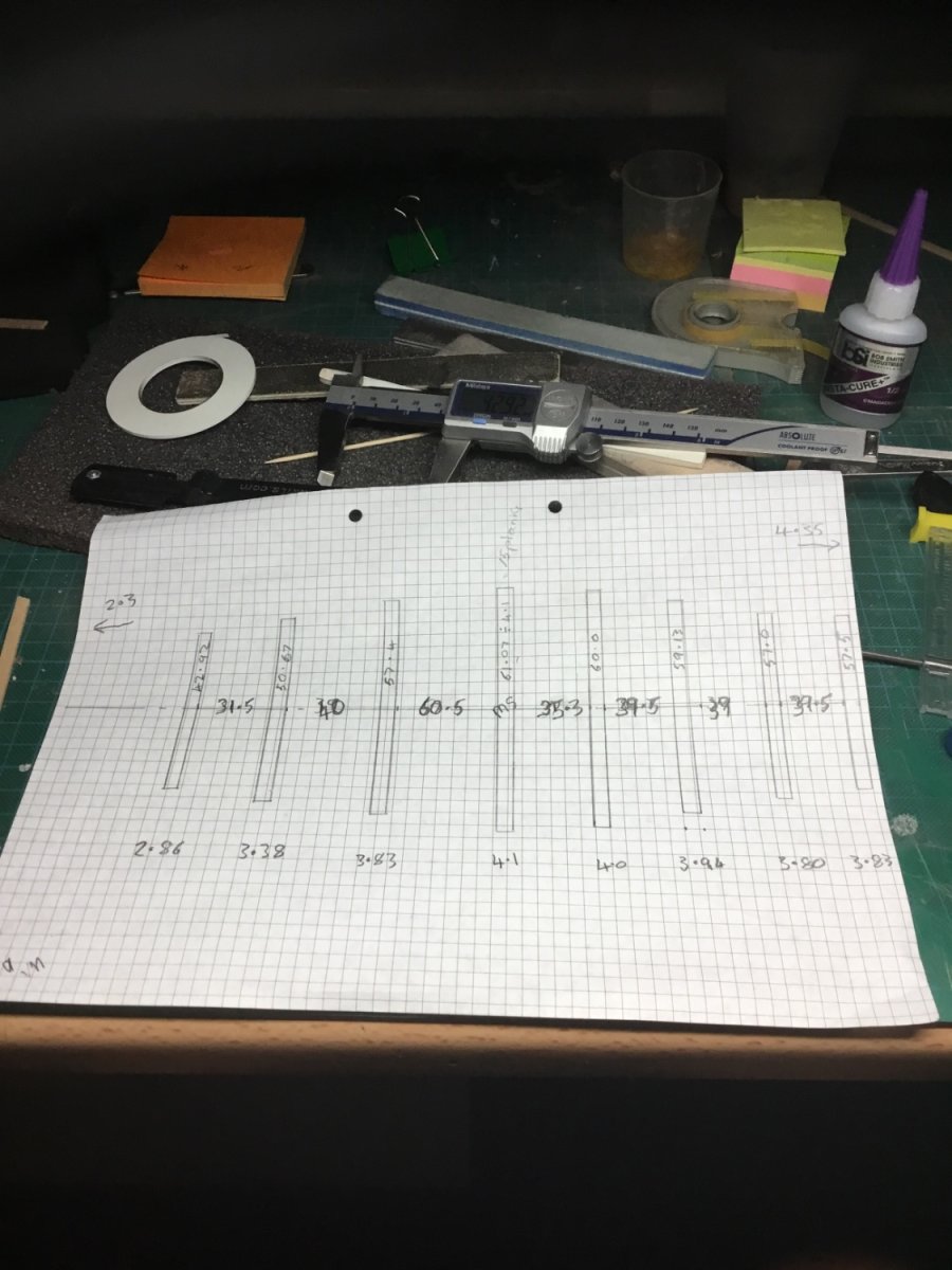
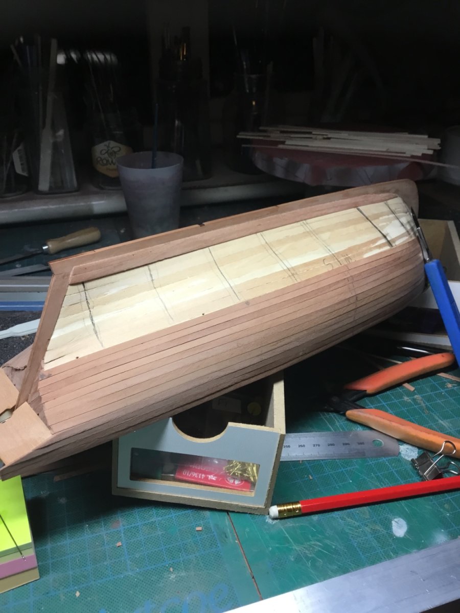
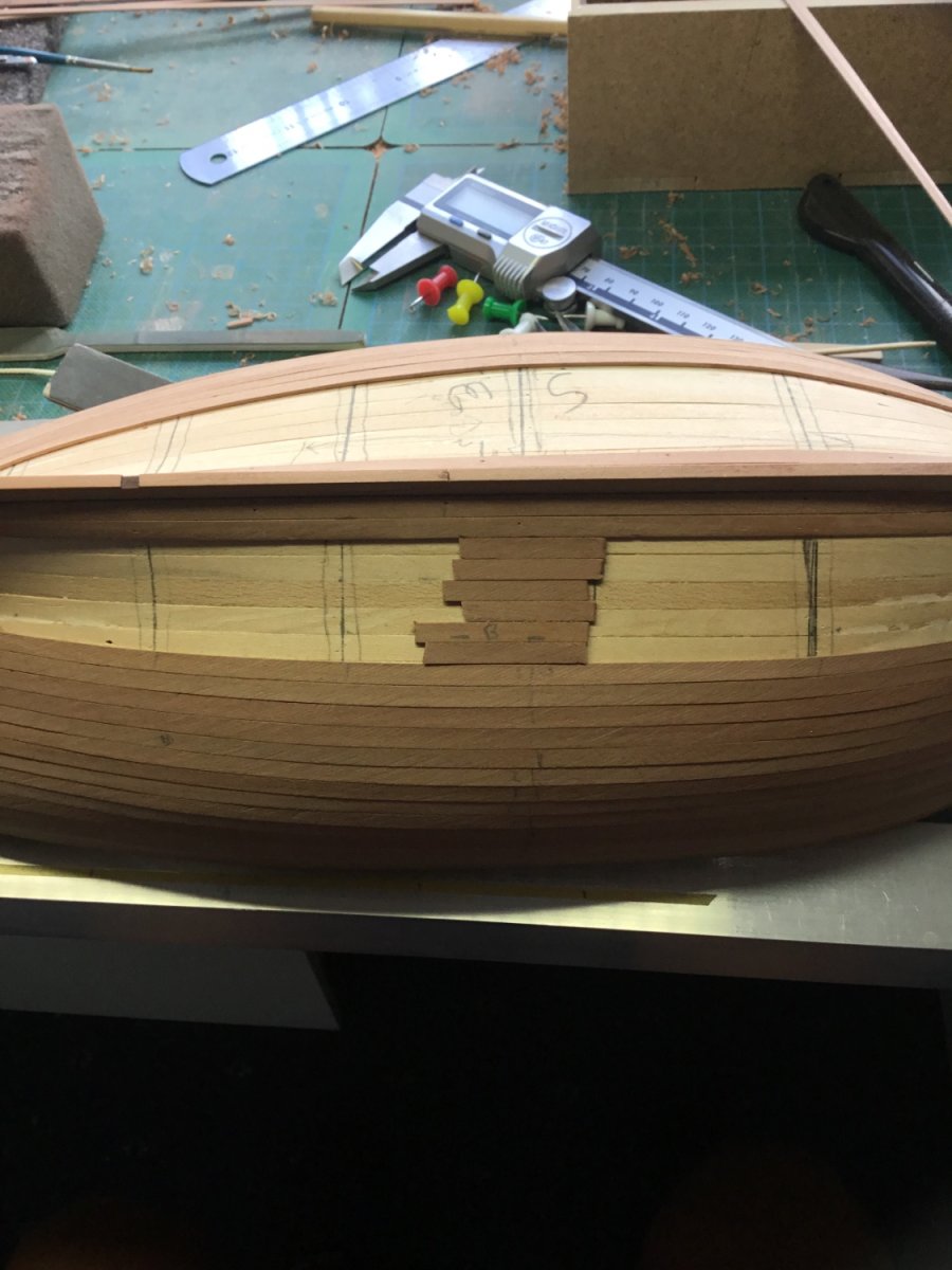
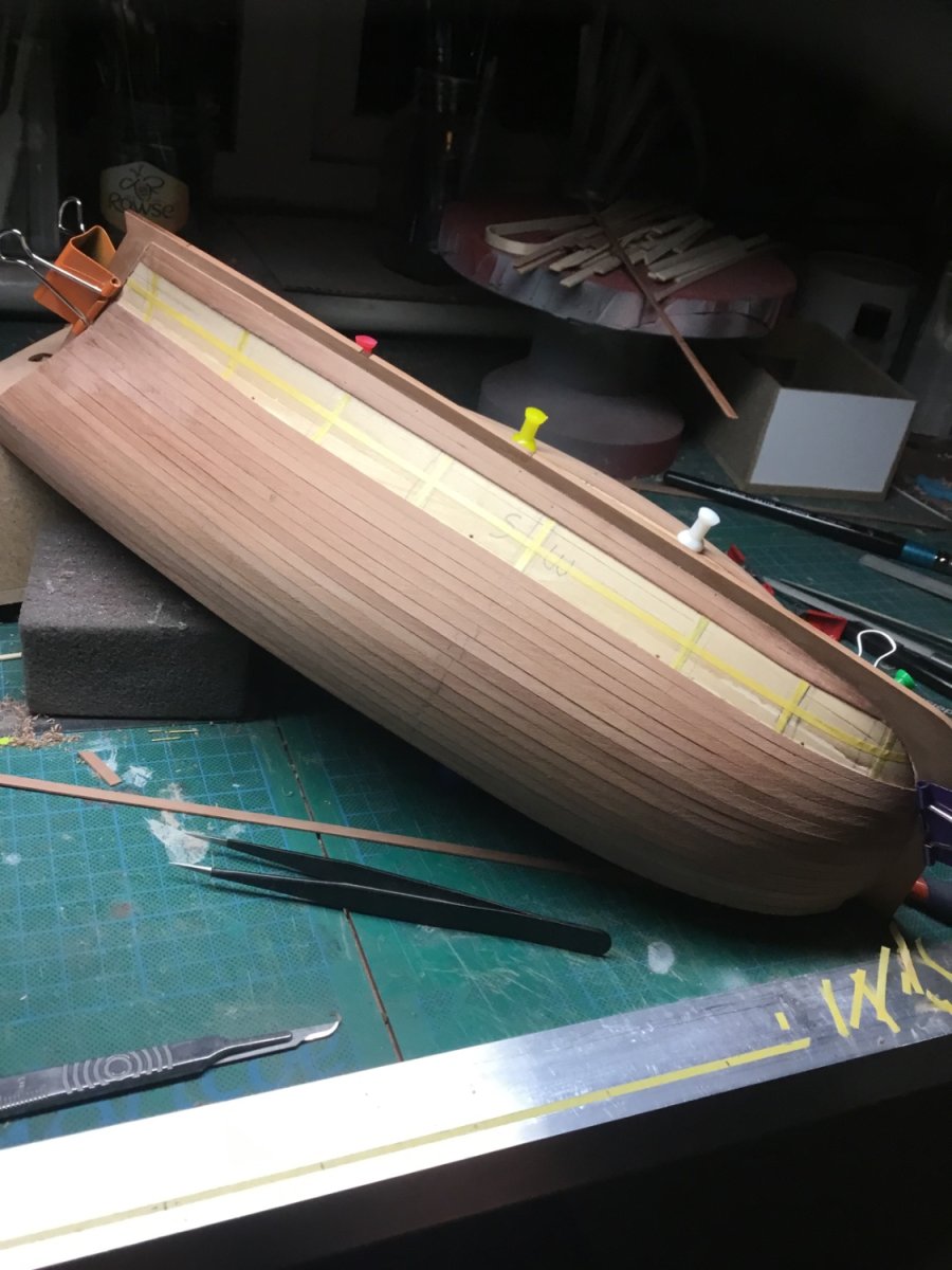
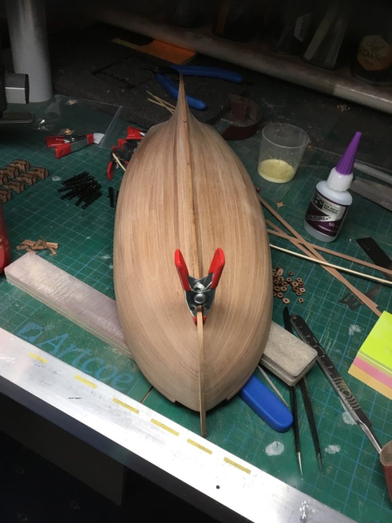
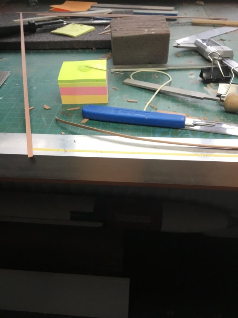
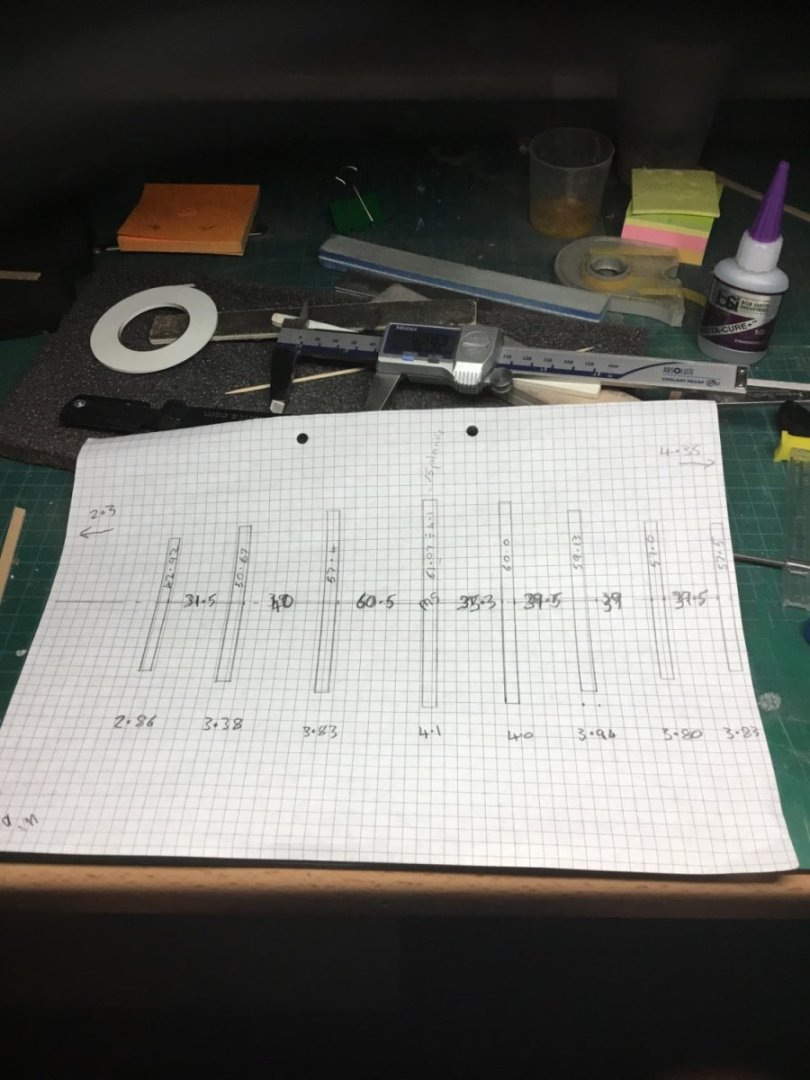
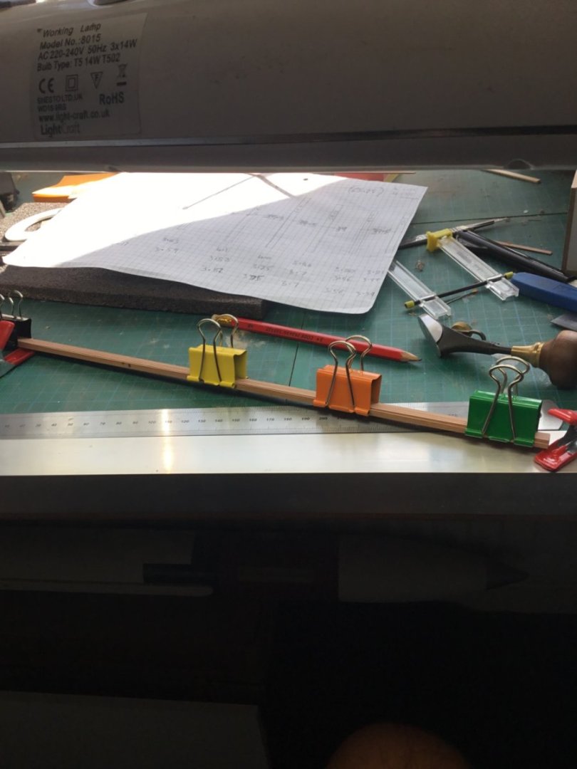
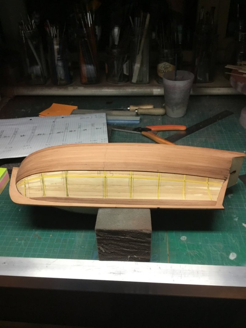
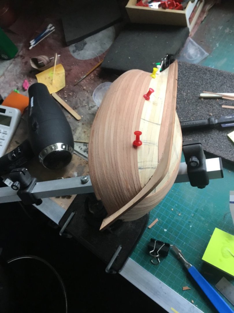
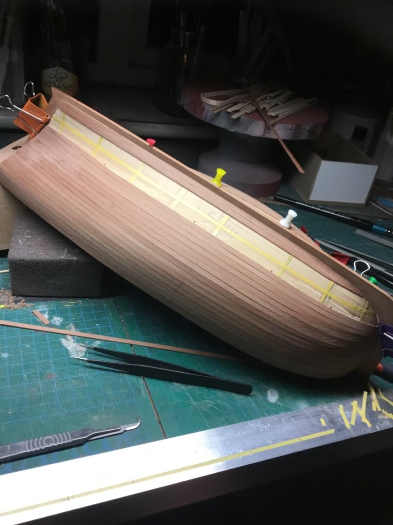
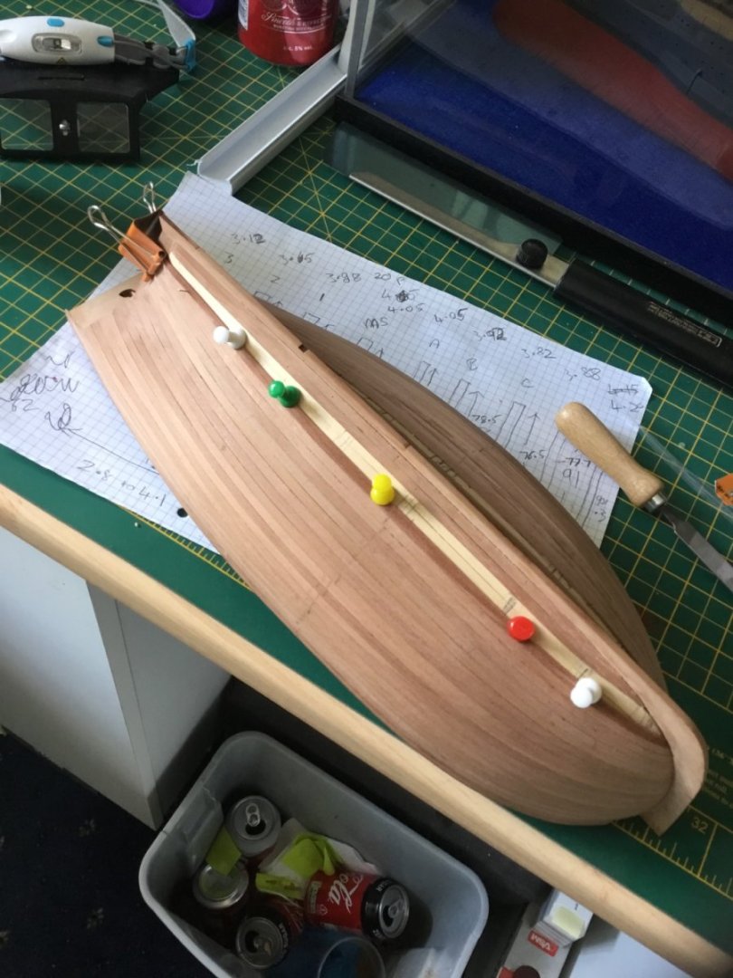
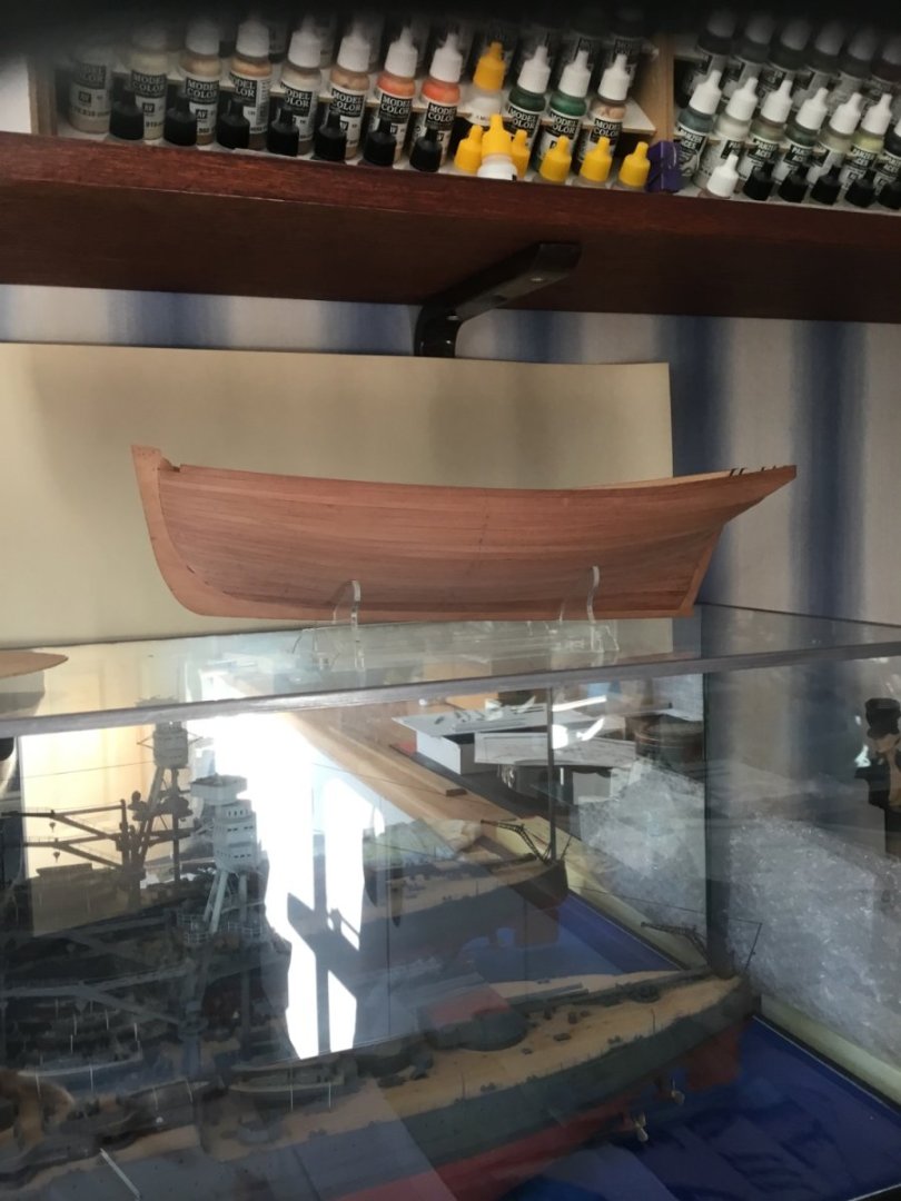
Fairly recently I came over to the other side and began wooden ship building. My first build was a Vanguard Fifie. I feel I planked the hull in the traditional beginner manner and although happy with the result I wanted to improve on my next build. Unfortunately I found this forum a little late and embarked using my own method. My second build was another Vanguard kit, HMS Alert. Here is breakdown of how I planked the hull. The first layer was done in the manner of my Fifie The next picture is after I had tested my idea with the first 5 planks. It shows me taking measurements for the second band. I have put tape between the lower and upper planks on the bulwarks position. I have also taped (in white) the length at a halfway position for a 5 plank band. The tapes were removed and the measurements put on paper. I had previously sorted the planking strips and for this band was using 4.1mm width planks. That gave me 15 planks at mid ships. I then divide each bulwark length by 15 and I get a plank width at each bulwark. I then make 1 plank to those dimensions making sure to mark midship position. This strake is now my pattern and I make nine more to the same dimensions. The planks are individually bevelled and fastened to the framework. This process is then continued for batches of 5 planks per side. I did change the tape from white to yellow Tamiya, as the white had too much stretch. Hopefully, the rest of the pictures become self explanatory. By the end it wasn’t too far out for a rough and ready method. I’m not suggesting this is a great method, but it was a step up towards lining off the hull in a more exacting manner. My third and current build is the Syren Medway Longboat so I suspect my ad-lib method will not be used by me again. Like I said, it worked for me at that time. Thanks for looking Paul


- 5 replies
-
- 15
-

-
Sorry for that Rob, just a bit of cross purposes. I agree with your approach on this. In fact some of those bits are so small I would probably be sticking them on with varnish! The paint would hold them in place. Cheers
-
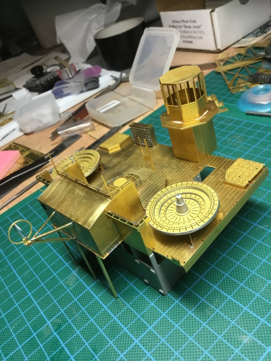
Love it, I have definitely shouted lots worse. That there is frustration. To be fair Rob, although you know the issues you have faced, your photo’s rarely show anything other than “job done”. It all looks really good, those racks look great and will improve even further when fitted and painted. They will become just another part of an “amazing” assembly. I got slightly involved in a conversation on here today about soldering, and your build here was at the forefront of my mind. I can’t help but think you are batting way above the production level of this kit. The plastic doesn’t look good but your etch work does. Cheers fella. Thank you Paul
-
Silver soldering
Toolmaker replied to Dziadeczek's topic in Metal Work, Soldering and Metal Fittings
Cheers, thanks. That combination build really leaves you with no option but to solder. To try and ca the David Parkins sets just wouldn’t bode well. The last paragraph that Dr PR (coincidently, my initials!) wrote sums up my method beautifully. It has to be said that almost all the soldering on that build is fairly thin photo etch but comparable to what many of us require in our modelling. Its a different story when working with solid machined parts and silver solder. Thanks Paul -
Silver soldering
Toolmaker replied to Dziadeczek's topic in Metal Work, Soldering and Metal Fittings
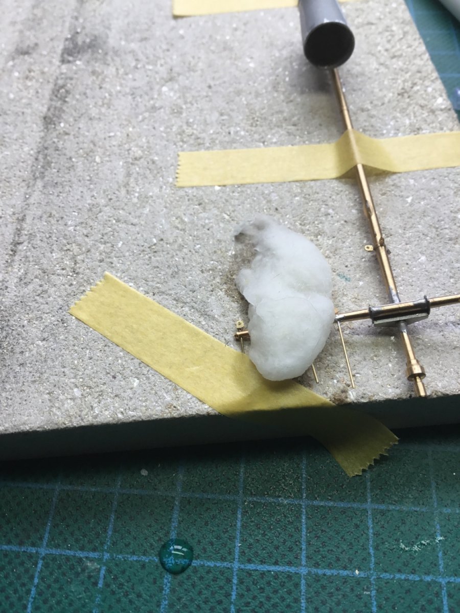
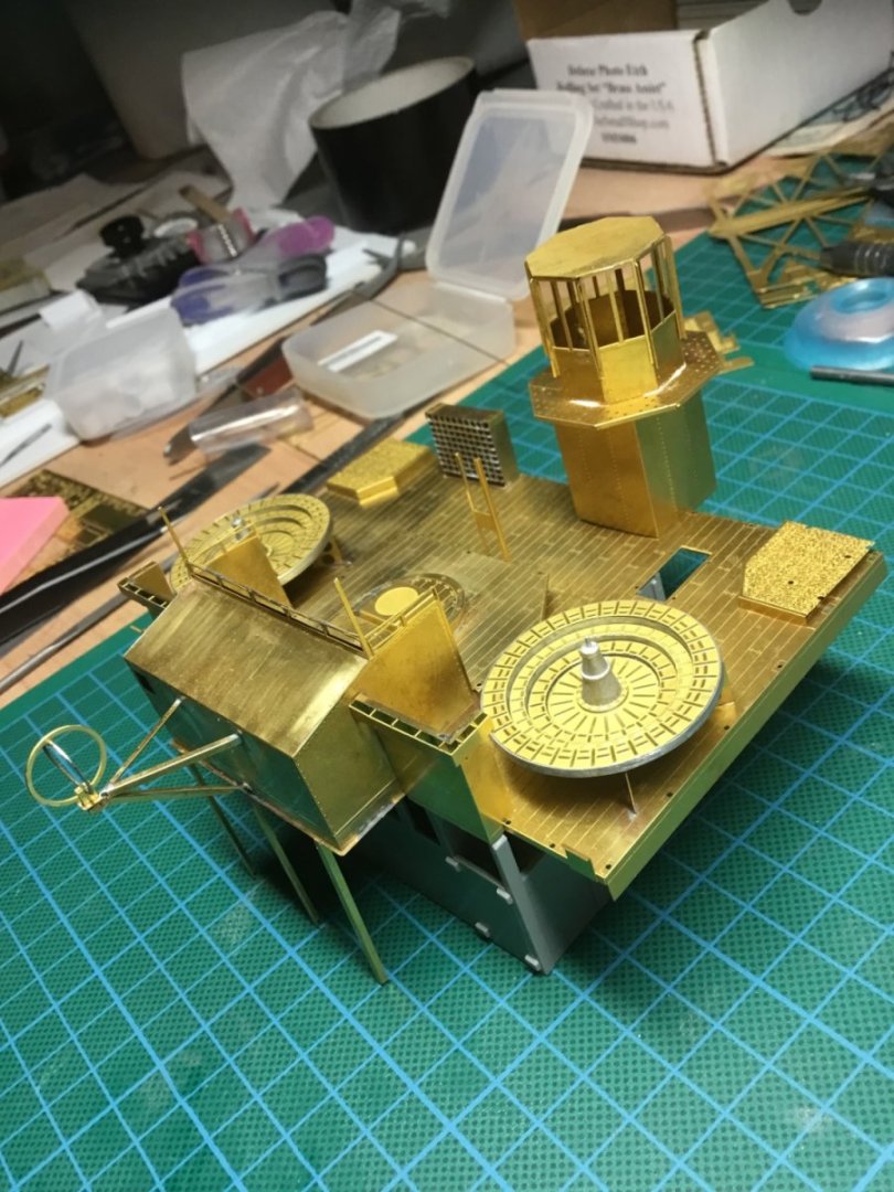
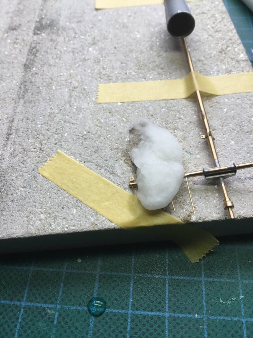
My thoughts entirely. It takes some effort to become proficient but after that it seems so simple. I believe I could teach anyone to solder small brass parts within an hour. The quoted paragraph is what I do, using a gas soldering iron. I have never considered a flame since. This component is 10 individual parts, I can’t imagine taking a flame anywhere near it, that would be a scatter gun approach. How small can you go using this method? Less than 0.4mm Getting close to other parts requires serious heat sinks. In this case it’s just wet cotton wool. The same method copes with bigger size parts equally well. If it wasn’t for the thousands of miles between most of us, we could set up a little soldering workshop. Thank you Paul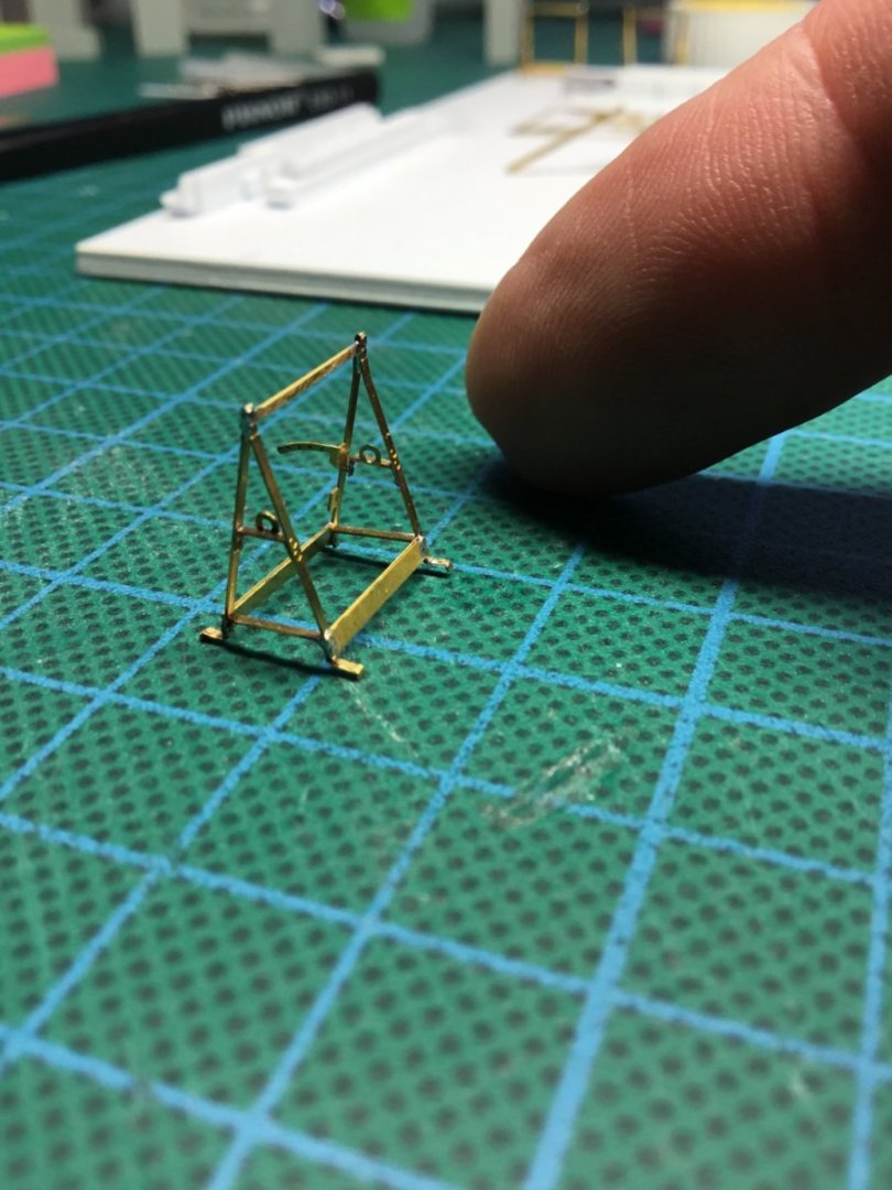
-
This brought back memories and had me chuckling. As for your fab build, it has become one of my favourites to follow. This is another aspirational build, the sort that creates a rush of kit buying. For me it’s the complete package, great woodwork, painted to the same level and now equally impressive fittings and rigging. Wow, I certainly have my work cut out trying to catch up with you fella’s. Thank you Paul
- 113 replies
-
- 1
-
-
- Cheerful
- Syren Ship Model Company
- (and 1 more)
-
Both inspirational and aspirational, which translates to, that’s beautiful work which I hope to match one day.
- 840 replies
-
- 3
-
-
- winchelsea
- Syren Ship Model Company
- (and 1 more)
-
https://qmro.qmul.ac.uk/xmlui/bitstream/handle/123456789/1703/PIETSCHShips'Boys2003.pdf?sequence=1&isAllowed=y I wasn’t sure if the document should be embedded or just linked? The link is to a large research document written using the records of the Marine Society. Still operating today, at the time in question the society was responsible for approximately 15% of Royal Navy recruitment. Page 149 shows a graph regarding Boys ages. Although only one portion of a larger picture I hope it is of some use. Thank you Paul
-
During the second half of the 18th century the London Marine Society registered around 4500 boys for sea service. Their stated minimum age was 14 although it was accepted that many boys younger than that may have been accepted.
-
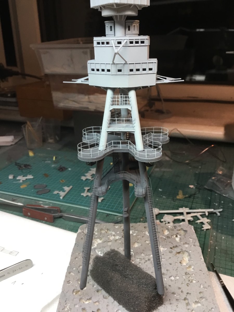
Hi Rob, yes spot on, that’s what I did in the end. The top half of the legs are hand painted although I had painted those curved railings prior to fixing them on. It’s at this point you end up thinking why didn’t I just stick to armour, ha. Ship building is so much more challenging. I went to 1/700 scale for a short while before moving to the wood stuff. That sure demands a steady hand. Regarding my own Arizona, at the moment there are just a few pictures in the gallery here. I did a build log on another forum some years ago but it has since gone. I may eventually repeat it on MSW as a retrospective log, but for now I will happily continue to enjoy yours. cheers Paul
-
You’re really knocking this into shape fella, it’s hard to see that and not be impressed. Great stuff. Just to add another level of awkwardness, when I did mine (in the easier 200 scale) I found during some research that the demarcation line for the paint colours wasn’t always as helpful as it could have been. Keep going, it’s fab to follow. Thank you Paul

- 115 replies
-
- 10
-
-

-
US 6” gun by RGL - FINISHED - Panzer Concepts
Toolmaker replied to RGL's topic in Non-ship/categorised builds
“It’s inside a cowling” Ha, now why didn’t I think of that 👍🏼 -
US 6” gun by RGL - FINISHED - Panzer Concepts
Toolmaker replied to RGL's topic in Non-ship/categorised builds
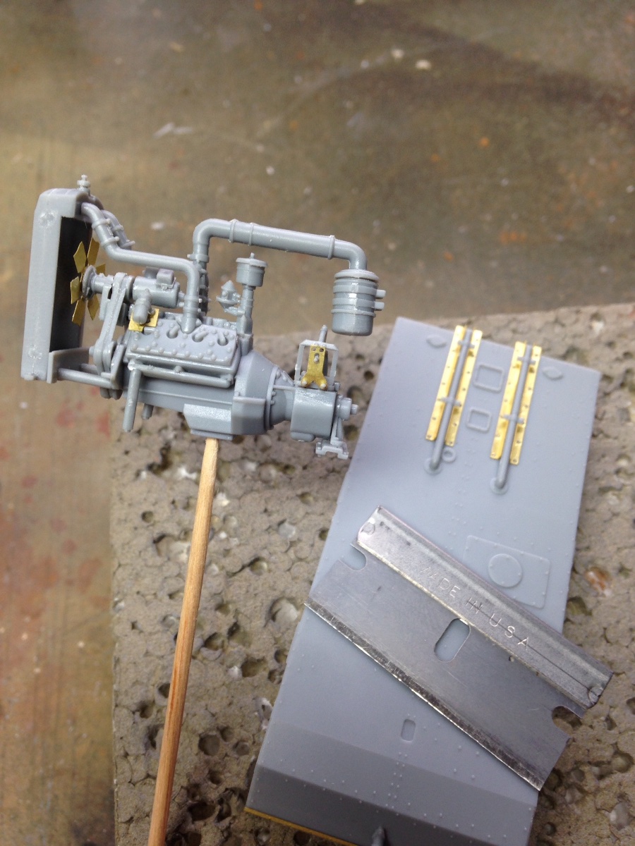
I’m appreciating your attention to detail, the kit looks very good, but your additions will make all the difference. The only thing I can think to add is you might have looked at thinning the fan blades. When I built a universal carrier the manufacturer had added etch for that particular item to offer better scale reproduction; Thank you Paul
- 235 replies
-
- 12
-
-
I would endorse the advice for uncoated hss bits from a reputable manufacturer. As has been said, at such fine diameters and without having the required rigidity, hand drilling with carbide is likely going to result in breakages. As for the pcb type drills, they are just not suitable for our modelling needs. They need very high revs and controlled feed rates offered by cnc machines. Without the controlled feed rates they tend to screw themselves into wood and any thin walled plastics and other sheet materials. The prices are very attractive but the results often disappoint. Thanks Paul
-
Introducing myself and already seeking advice
Toolmaker replied to kdm's topic in New member Introductions
I think 5 or 6 years is a touch late. Or did I miss something 😂 -
Looks good to me too
-
uploading pictures
Toolmaker replied to David56's topic in Using the MSW forum - **NO MODELING CONTENT IN THIS SUB-FORUM**
Mark, Thanks for the help. I’m not quite there yet and it’s not an important issue, but at least I am no longer just a T in someone else’s alphabet. I whatsapped myself which compressed the picture. Then saved it and used it here. It ended up half the allowable size. It’s a start and can wait until another day to refine. Thank you Paul -
uploading pictures
Toolmaker replied to David56's topic in Using the MSW forum - **NO MODELING CONTENT IN THIS SUB-FORUM**
Hi folks, I am managing fine to upload photo’s in topics, replies etc. However when I try to upload a picture to my profile I am told that the file is too large. Can I edit the photo on an iPad and upload it direct as I do with other photo’s. When I have uploaded photo’s from the iPad to other topics and gallery’s it has done so without any request to re-size. I hope that makes sense to at least one able person. Thank you Paul -
US 6” gun by RGL - FINISHED - Panzer Concepts
Toolmaker replied to RGL's topic in Non-ship/categorised builds
Lovely 3D printing detail and the opportunities for a diorama seem endless. I’m looking forward to seeing what you do with this beauty. Thank you Paul -
Another high bar Winchelsea build to follow. I’m feeling blessed to have so many excellent examples to learn from. The planking looks superb. Thank you Paul
-
Hello Glen, I’m fairly new to wooden ship building and this is my first comment on your build, so hence the formality. Your log is both inspirational, educational and a pleasure to read. Yes, there are multiple wonderful builds of this model, but the detail you show, whilst not being over repetitive is a perfect fit for me. I hope you don’t mind but I have a question on the use of the monofilament fishing line, used to represent bolts. So far, I can only see the “size” given as the breaking strain. I was hoping you could measure the diameter used and quote that either in MM or English. My concern is that different manufacturers will offer varying diameters for a given breaking strain so a known size would be useful. Of course if I knew the size of the ship builders bolts/nails etc, I could scale them myself. I intend to commence with my own build of HMS Winchelsea later this year and your build will be my favoured mentoring resource. Thank you Paul
- 840 replies
-
- 4
-
-
- winchelsea
- Syren Ship Model Company
- (and 1 more)
-
Still cheering and willing you on from the sidelines. Your words about the integrity and how delicate the build is, bought back uncomfortable memories of my own efforts. I actually did experience blowing parts from the build with an airbrush and did also lose parts only to find them up a finger nail. If you remain determined to continue this madness for years to come you may also conclude that taking soldering to an art form becomes a must. Like yours, my Arizona etch to etch was all held with super glue as it was also my first ship build. However, after that, any subsequent etch to etch build was going to be soldered. After some practice I found I could solder the tiniest of pieces and the smallest of diameters. Once learned, the stress levels plummeted. You are also on the money when noting the demands of planning for painting. Unlike many modelling subjects, ships have a lot of fine detail above decks, requiring careful planning. Many detail parts need painting off the model and adding after. Enough waffle from me, keep up the good work. Cheers Paul