
ERS Rich
-
Posts
761 -
Joined
-
Last visited
Content Type
Profiles
Forums
Gallery
Events
Everything posted by ERS Rich
-
 Thank you JS for the recommendation. Have to give credit to the Robert E Hunt practicum. Will definitely checkout Ken’s work. I like seeing how others do it and figuring out how to do it in my shop. Also this is the first project fully using the Byrnes table saw, the sliding table takes it to another level - safely and precisely cutting small pieces of wood.
 -
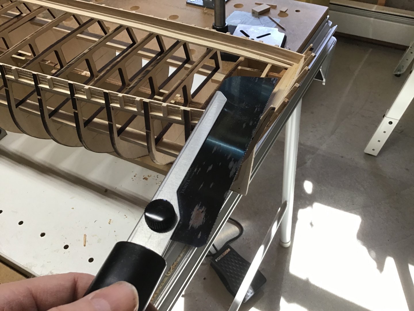
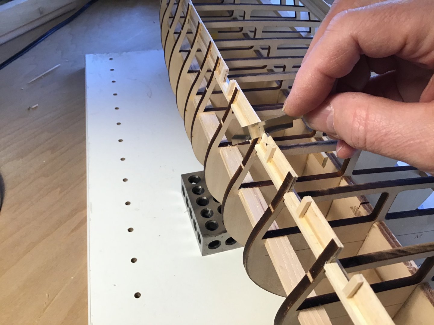
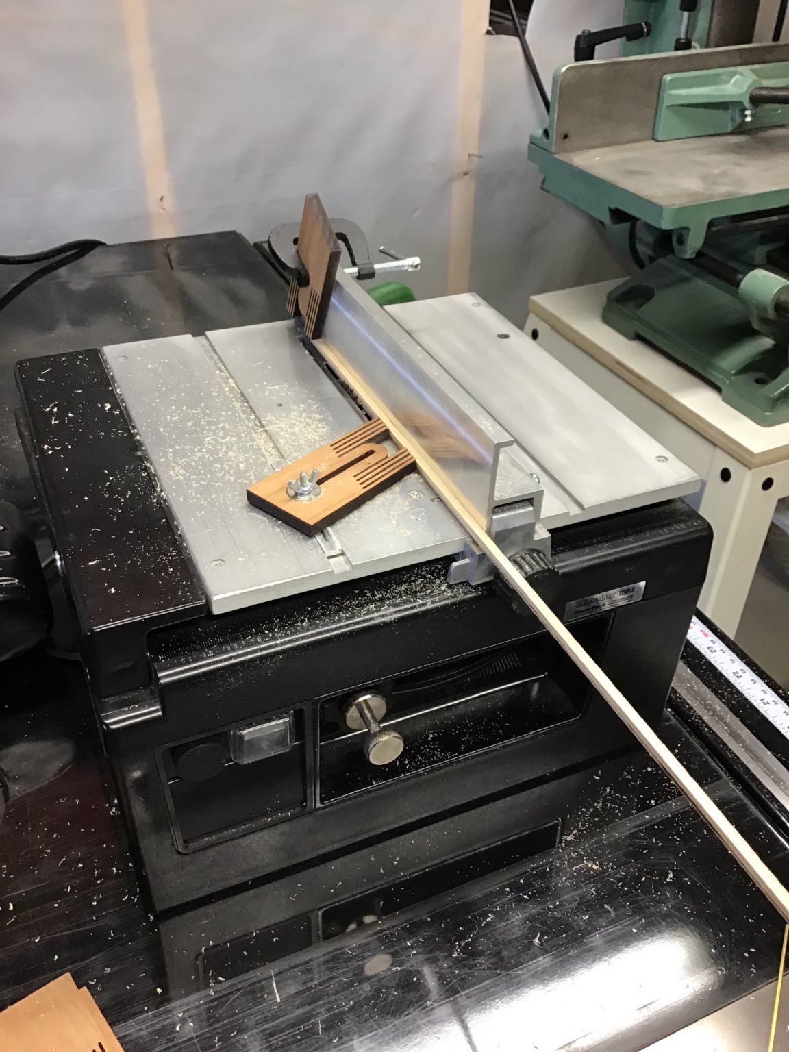
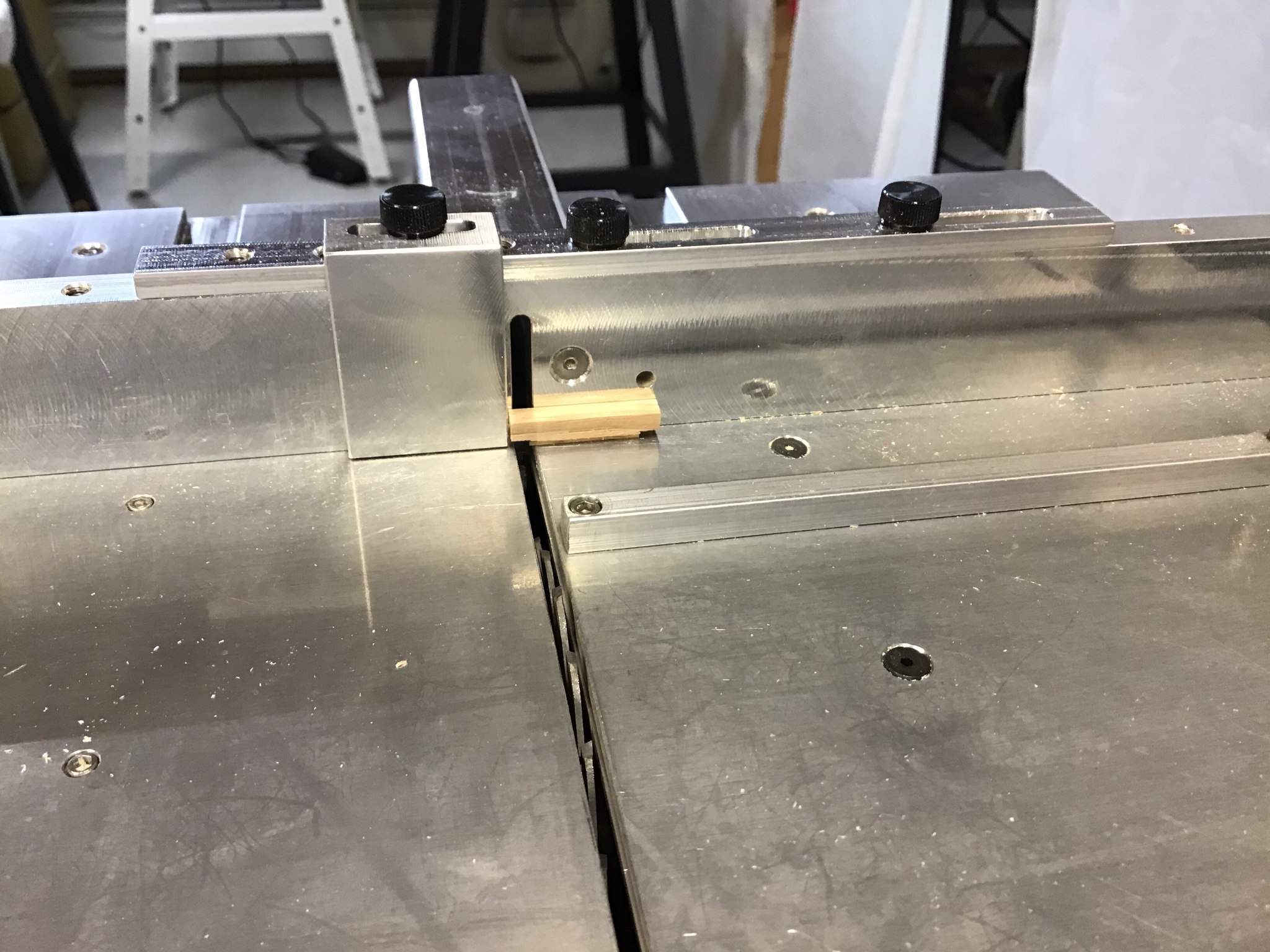
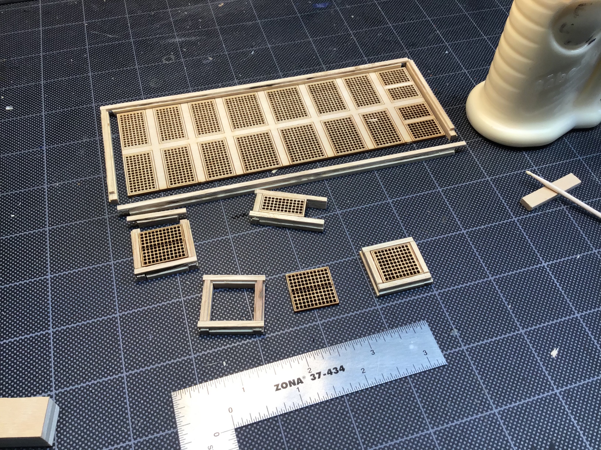
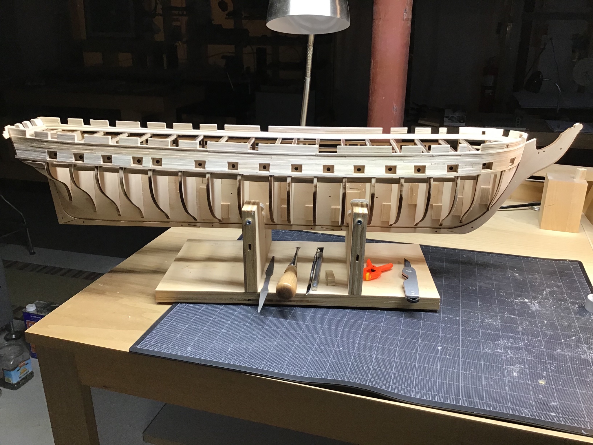
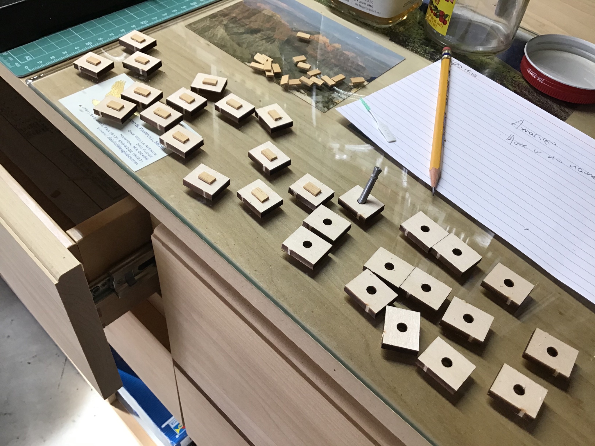
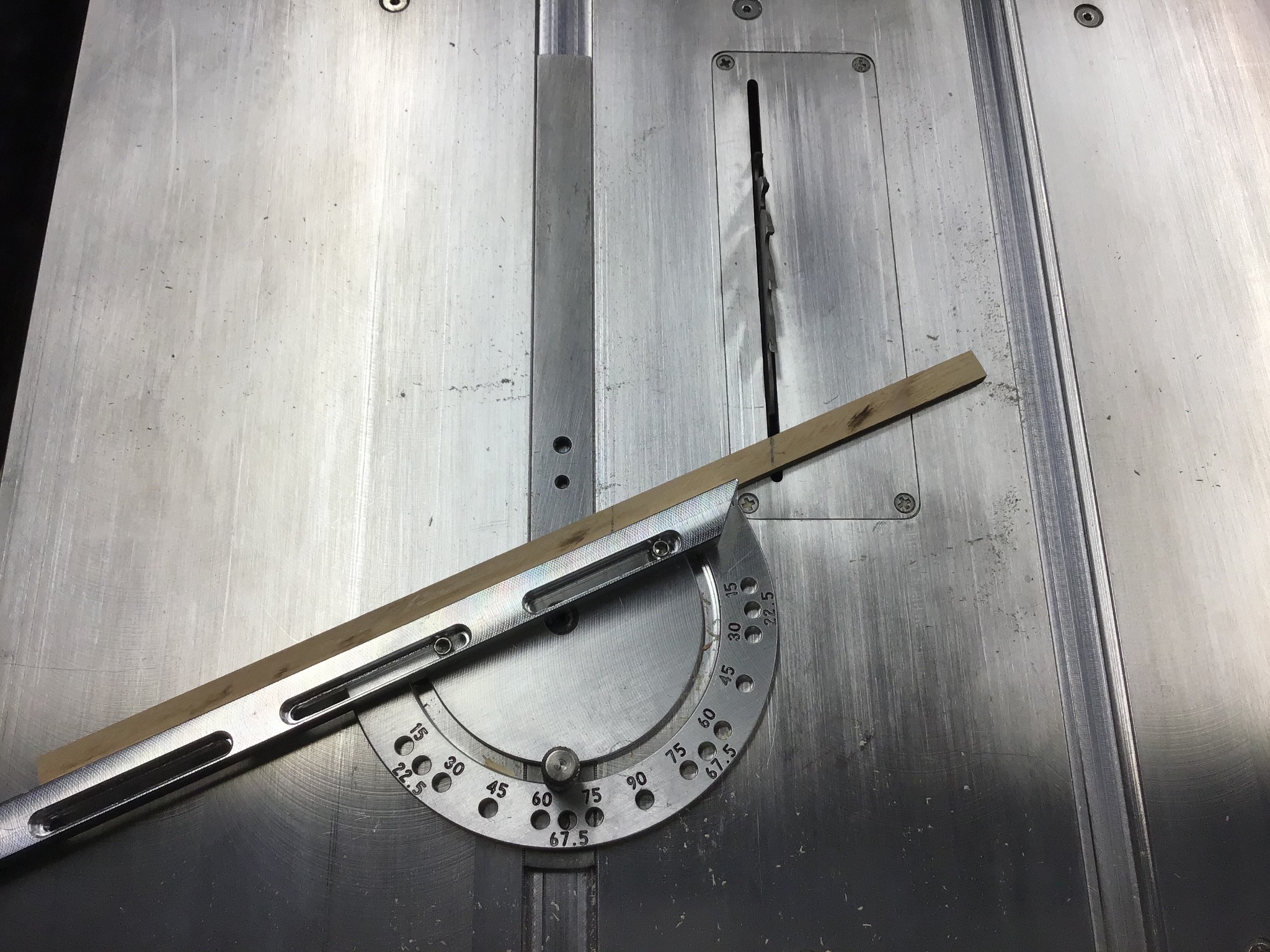
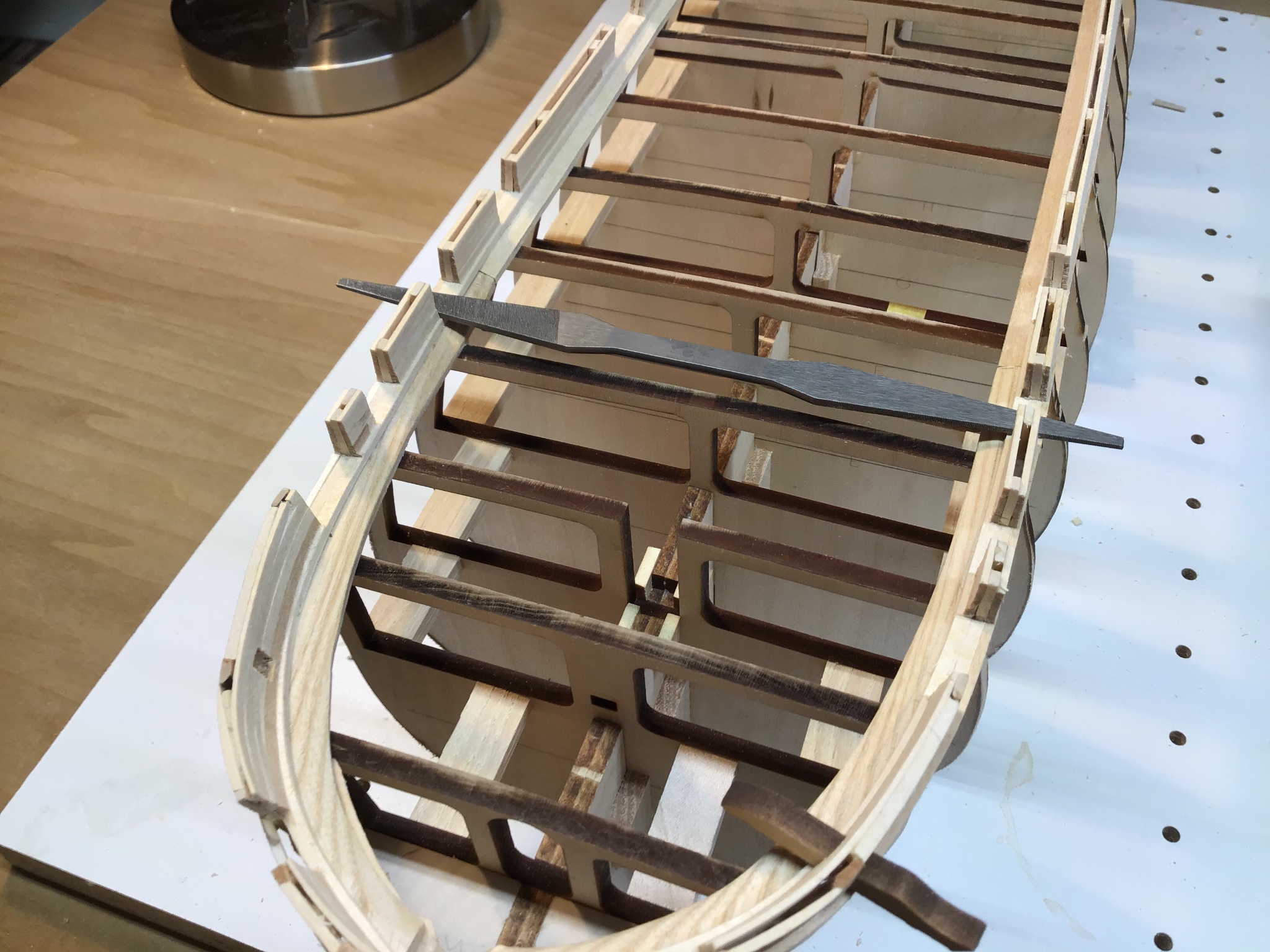
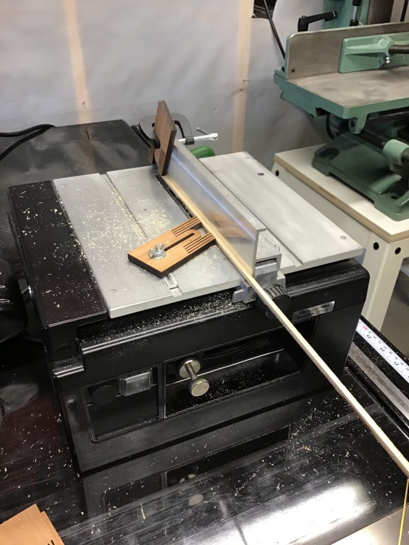
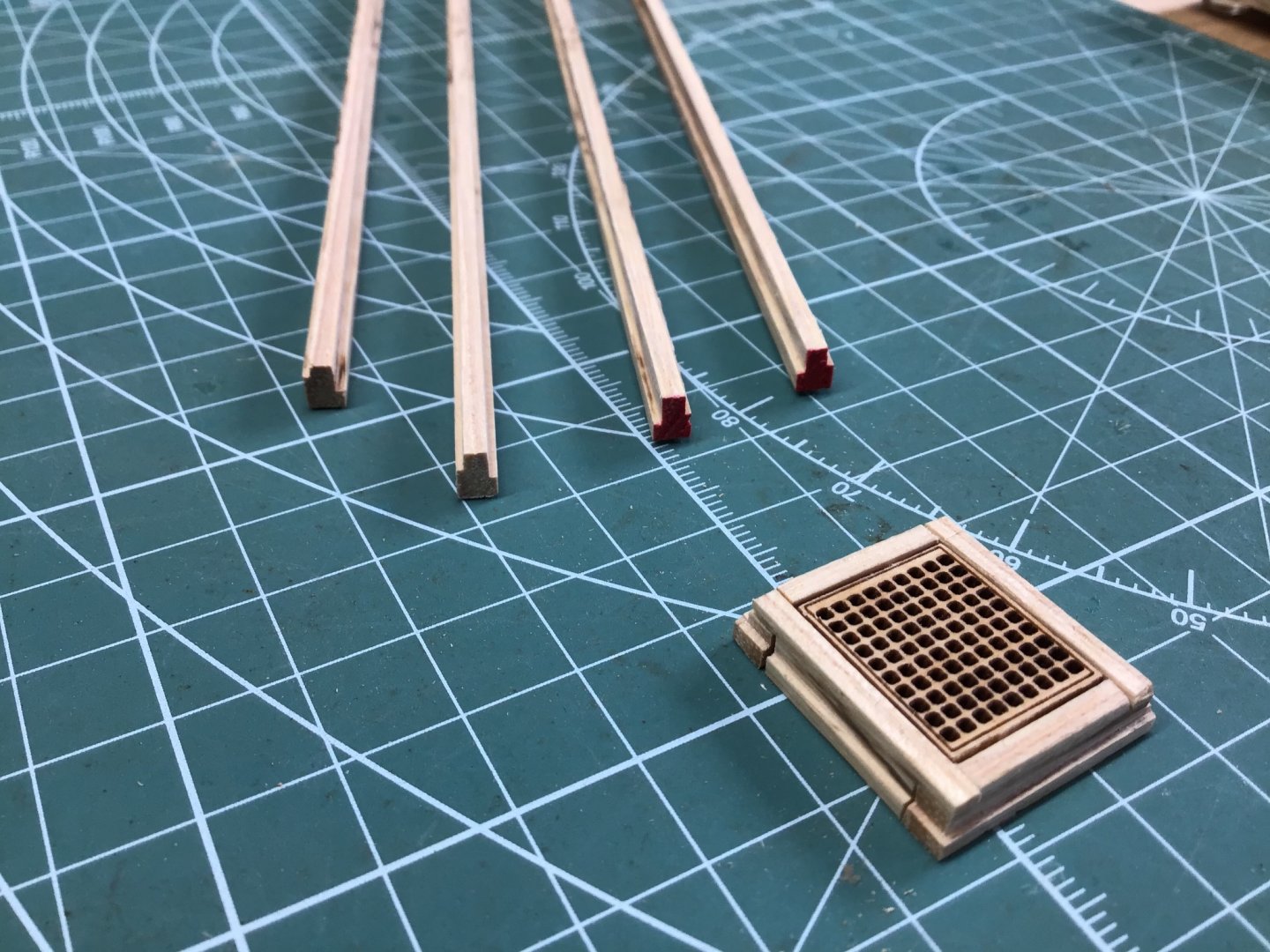
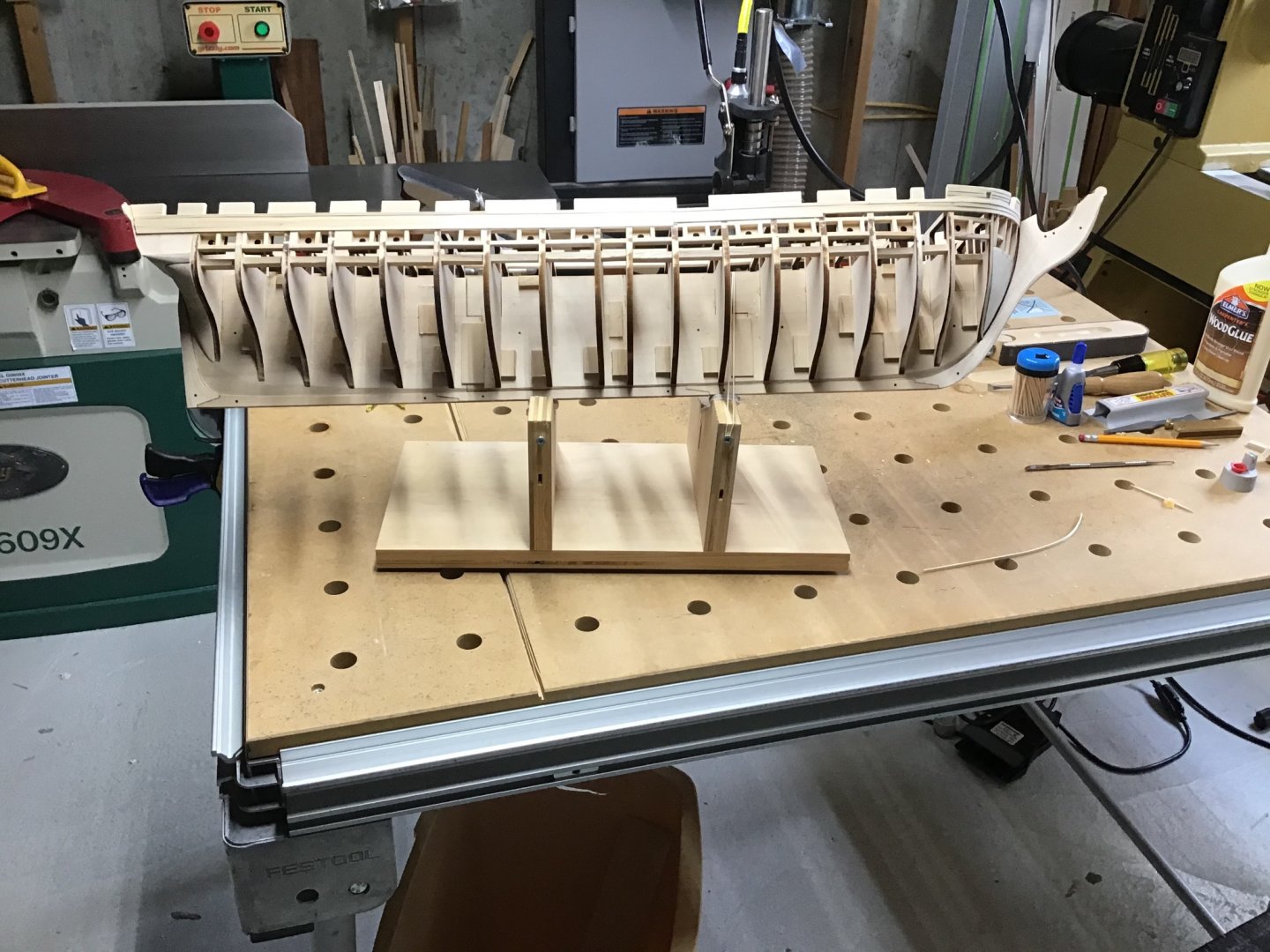
Coamings and Hatch Framing The kit calls for the builder to use 3 pieces of stripwood to build up the coamings (base moulding around the hatches and companionways. Doable but difficult. Instead I used hickory hardwood as stock and milled it with the Byrnes table saw. Start by milling the stock 5/32” wide by 7/32” high. The job is to cut two rabbets 1/32” wide, one 1/16” deep for the inner lip the grate sits on, the other 1/8” deep leaving 3/32” for the outside lip forming the outer base moulding. Set the table saw fence to 1/8” (4/32”). This leaves 1/32” for the rabbet width on the outer edge. Feather boards are needed to hold the stock against the fence and the table - Picture 1. Set the blade height to 1/16”. Cut the first rabbet. Set the blade height to 1/8”, flip the stock around and cut the second rabbet. Picture 2 shows milled stock, notice the rabbets on the outer sides. Next is framing the grate. In this procedure we’ll refer to the long side and short side of the grates, and will cut long sides and short sides of the coaming stock. The coaming sides need rabbets too, the coaming short sides will have the rabbets cut on top, the long sides on the bottom. First measure the length of the short side of the grate. Short sides will have a 1/8” wide rabbet on each end that is 1/16” deep. So the coaming short side length is the measured length of the grate short side plus 1/4” (2 x 1/8”). Cut the coaming short sides and cut the rabbet on the top side of each end 1/8” wide by 1/16” deep. Picture 3 shows the fence setup on the sliding table ready to cut rabbets for the short sides 1/8” wide by 1/16” deep. Next dry fit the coaming short sides to the short sides of the grate. Measure the width of the assembly. This width of the assembly is the length of the coaming for the long side. Cut two coamings for the long sides. Last is to cut the rabbets on the bottom of each end 5/32” wide by 5/32” high. Glue up the frame. Cut the excess stock in the corners so the outside edges match up. Last picture shows the process, bottom left to right, from dry fitting, glue up, and finished product with excess material removed to even up the outside base.


-
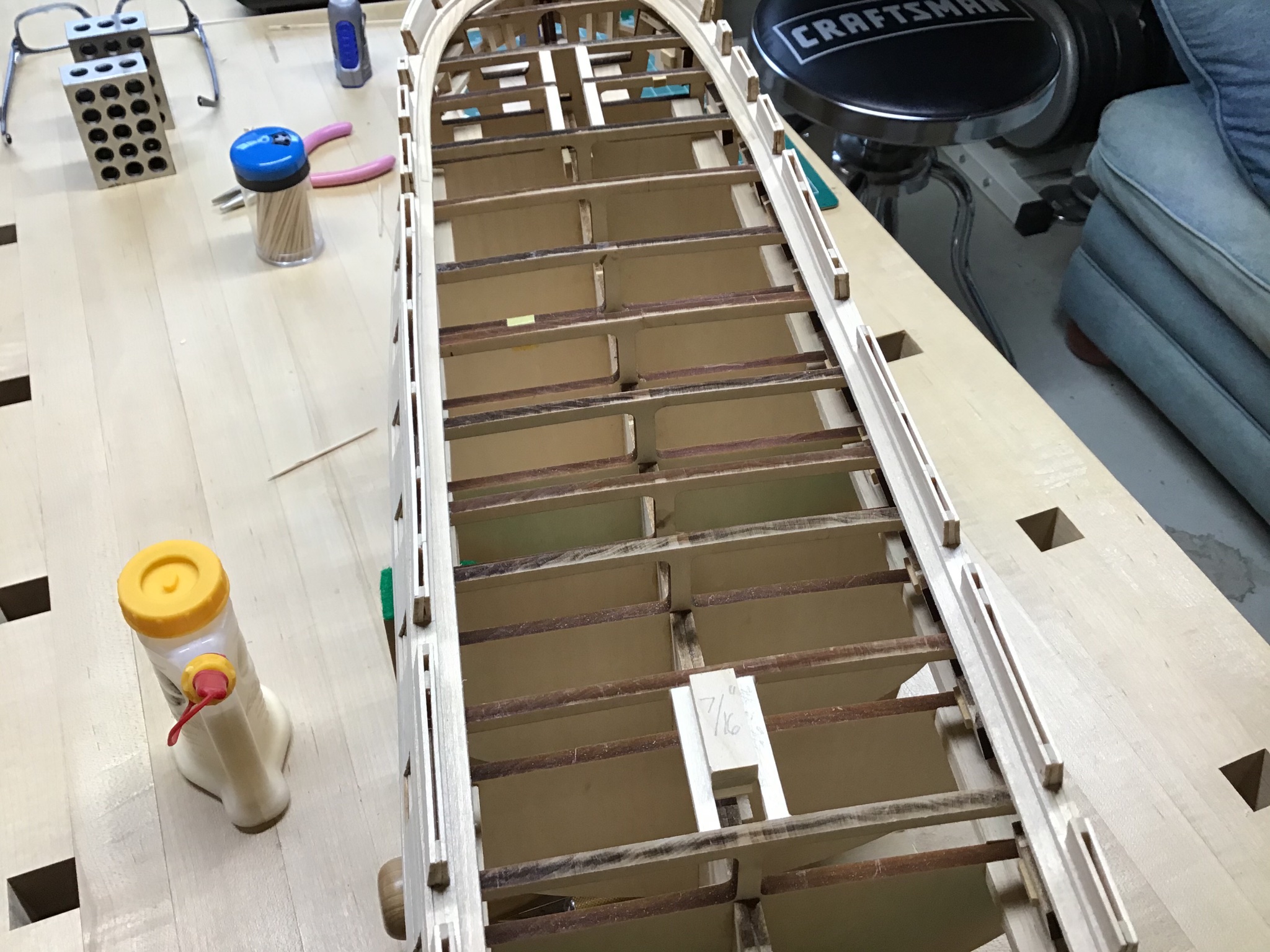
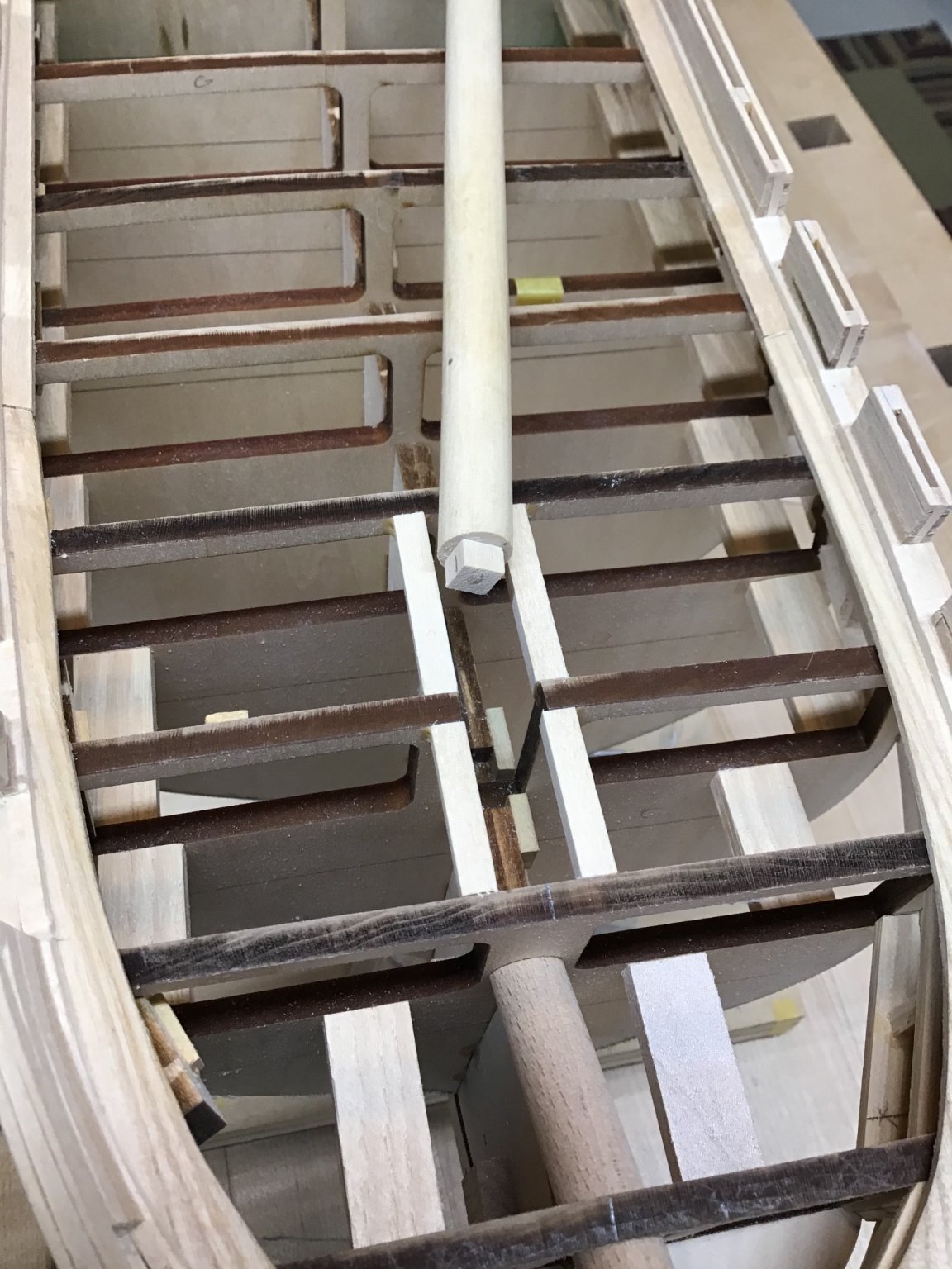
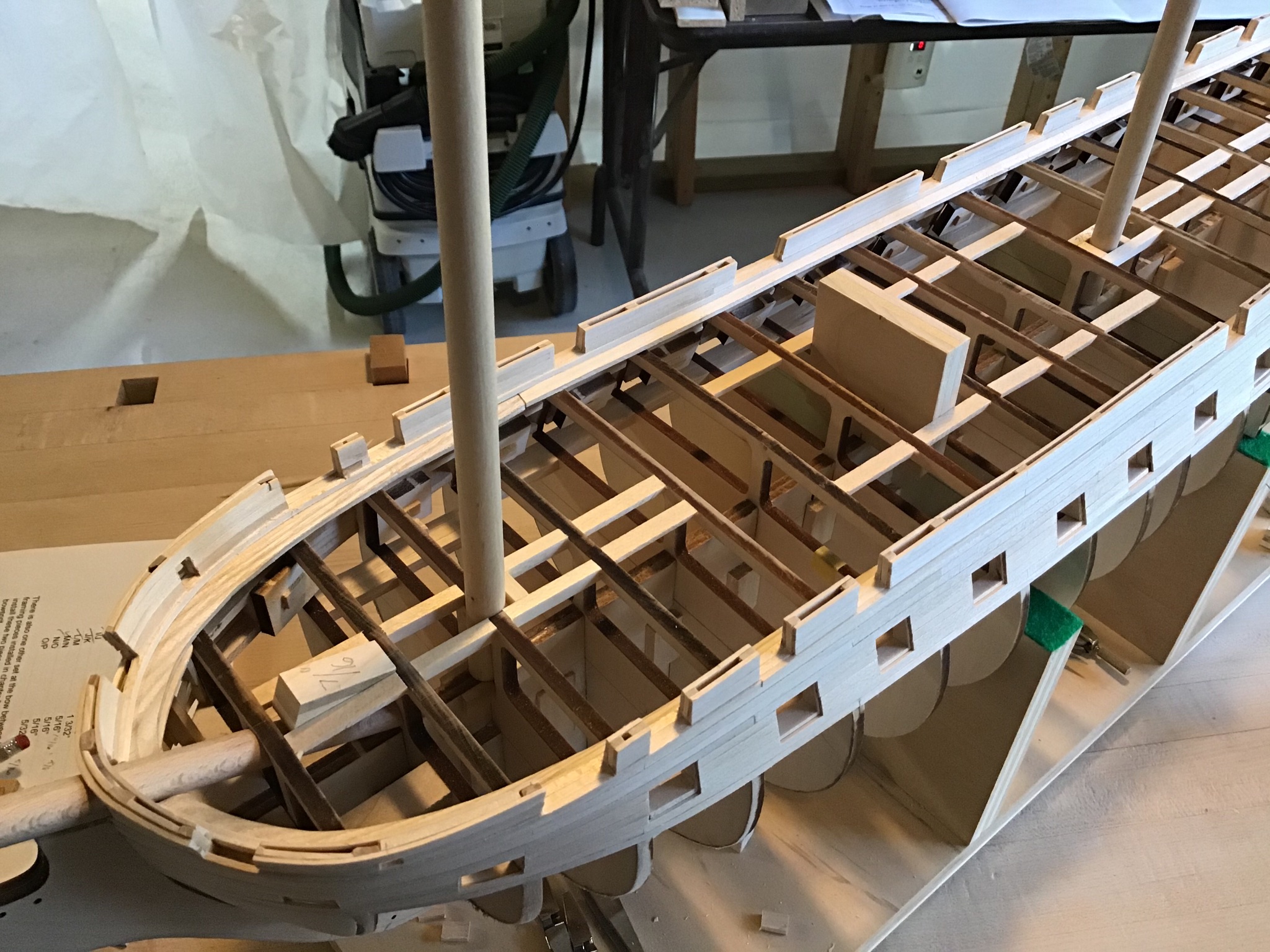
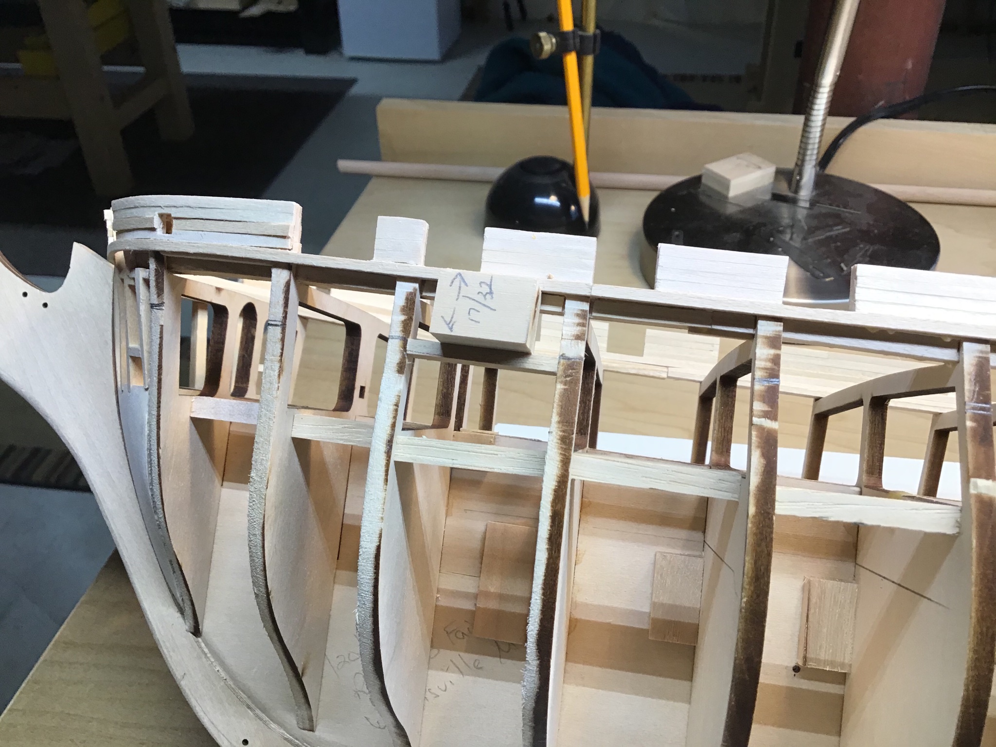
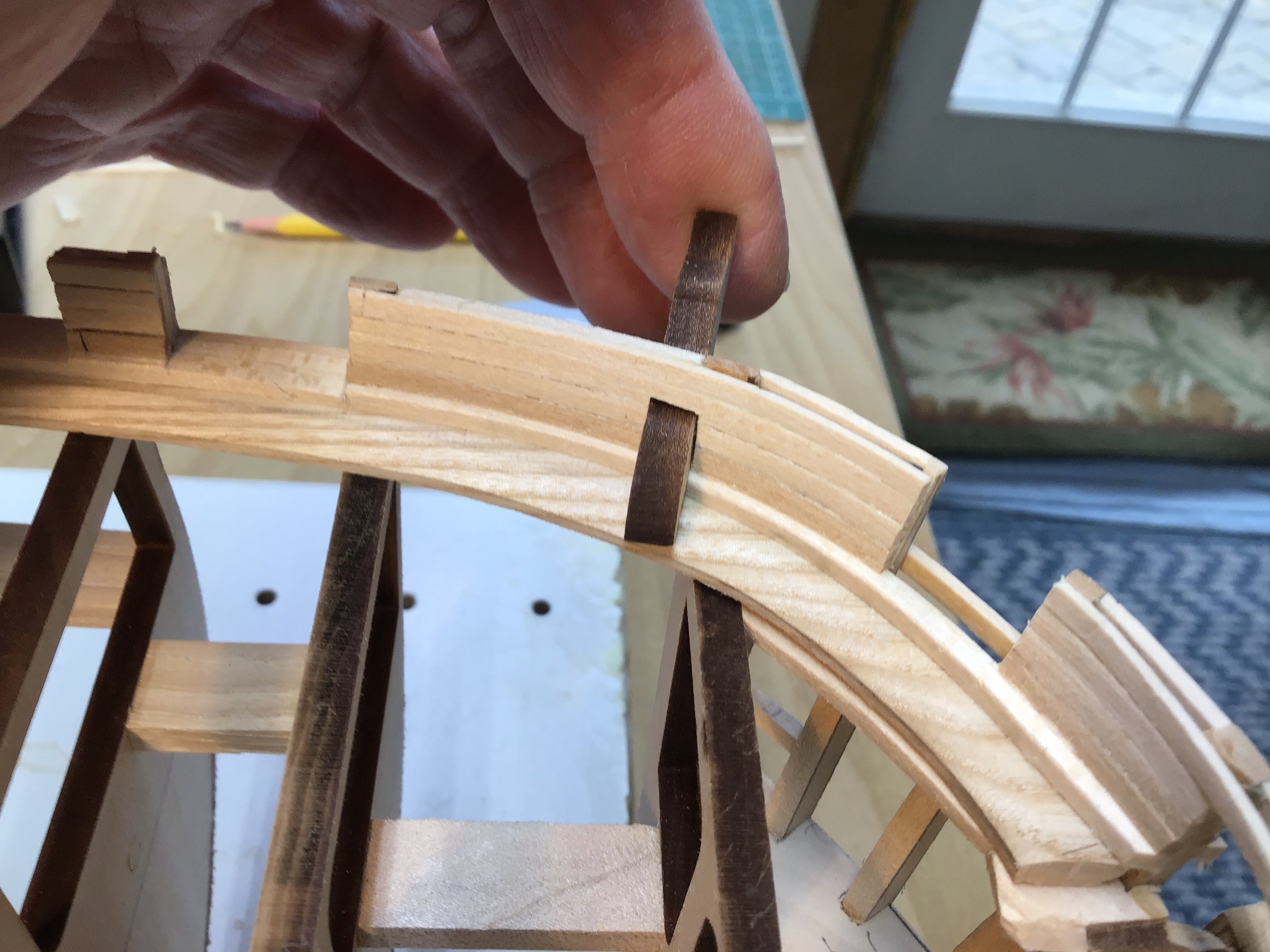
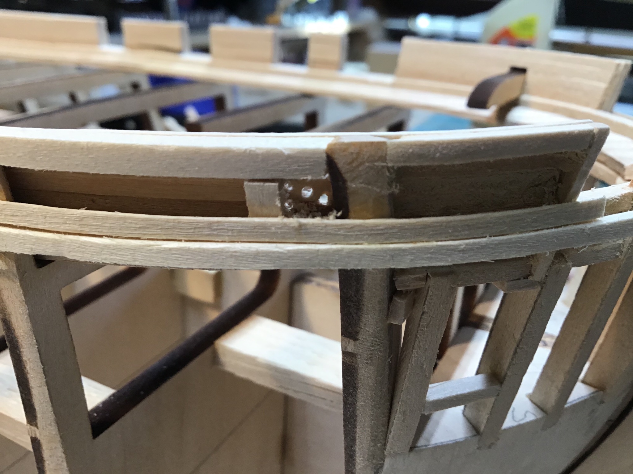
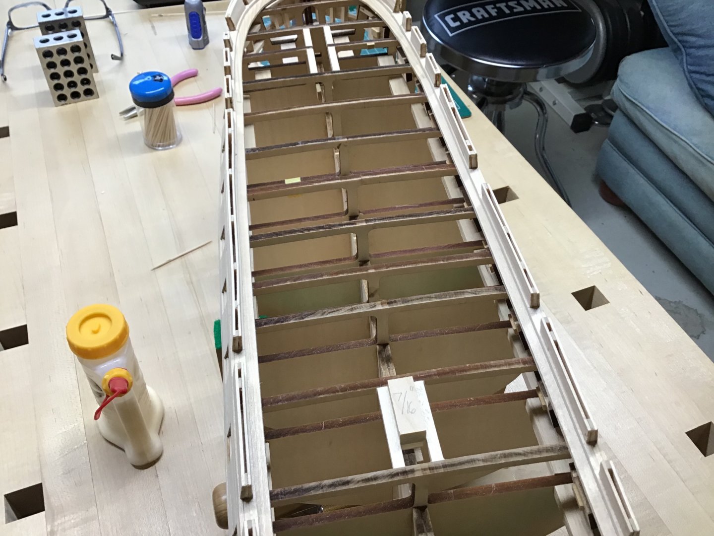
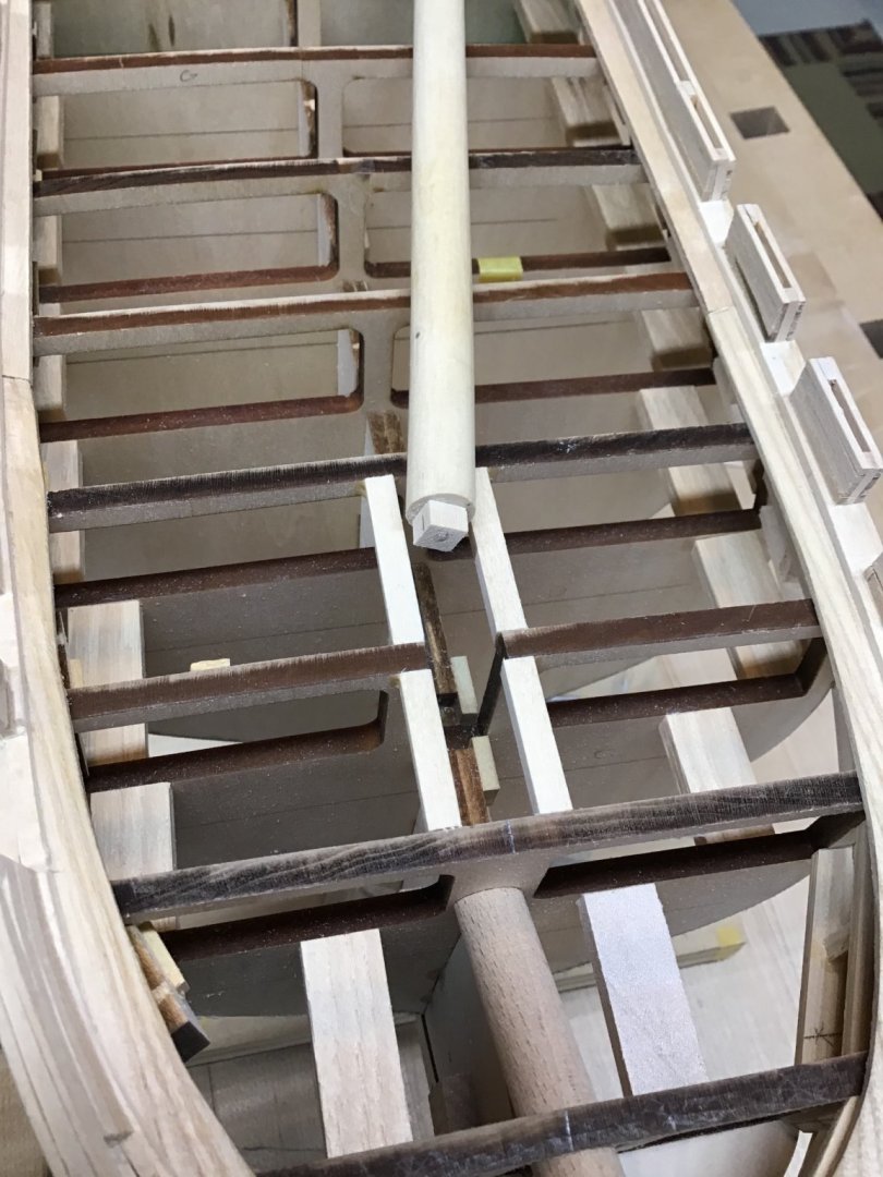
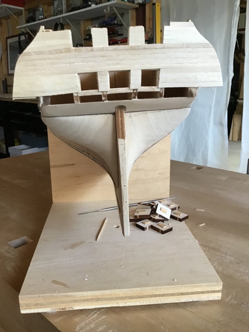
Mast Partners/Tenons and Deck Framing Used spacer blocks to locate the mast partners. Established mast angle be cutting the bottom mast face at the correct angle on the Byrnes saw. Glued and doweled tenon to mast face. Test fit masts. Also located deck framing for hatches with spacer blocks. Hatches will sit on deck frames with deck planking around them.

-
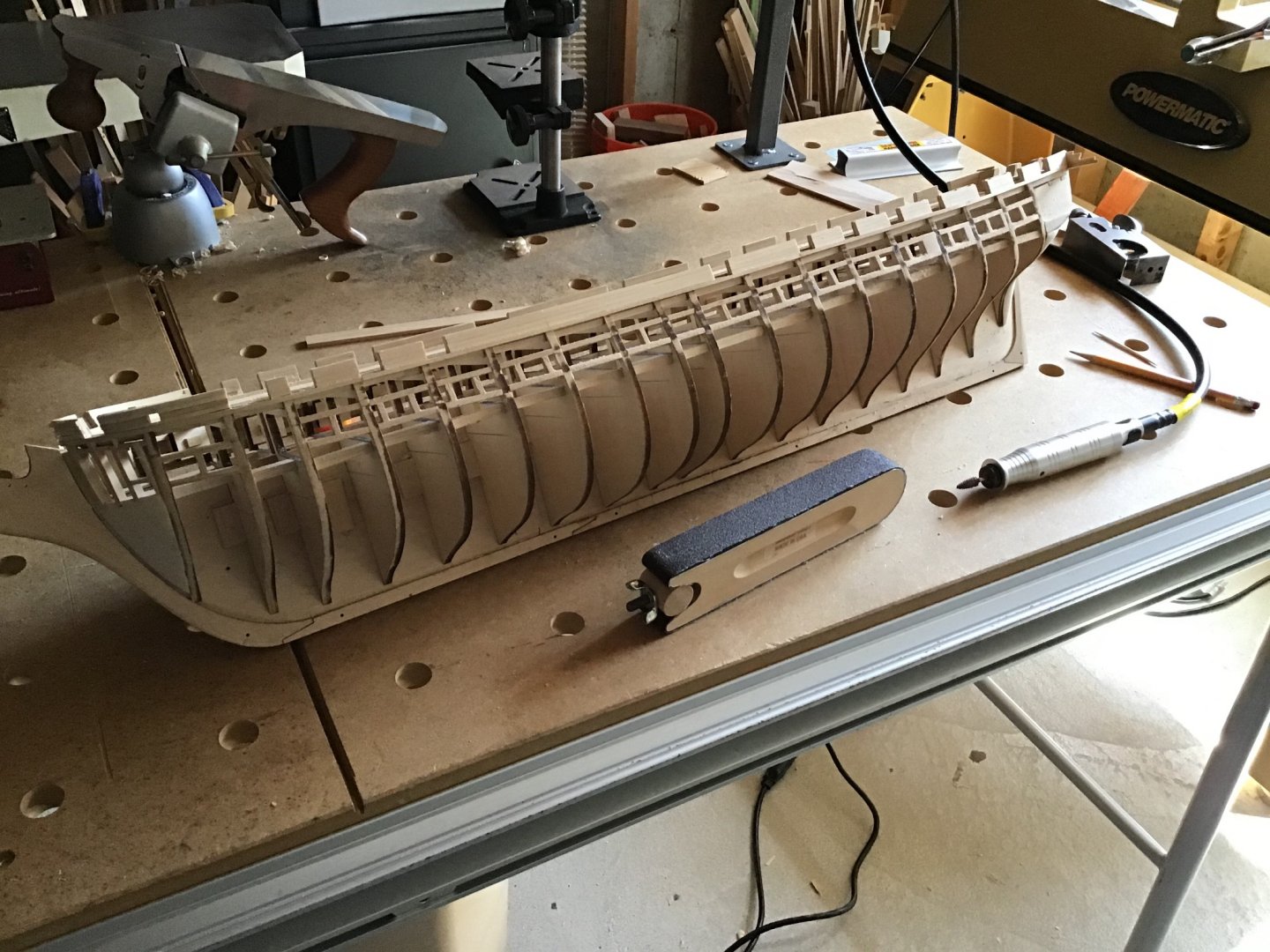
Gunports and Upper Hull Planking Completion After learning how to do it on the starboard side, completed the port side gunports and planking a little faster. Pictures show rough sanding of the gun port sills and side frames, using a sanding block. And the Foredom hand piece with a flame shaped bur. Foredom offers hyper tight control of material removal on the sills and frames. First time using the Foredom for this task and a huge time saver. Installed the side extensions and planked the transom. Finally smoothed the planks with a 12” long wood file and the Amati sanders as necessary. Wiped her down with alcohol to knock down the fuzzies and clean her up. Still some smoothing work to do but about 90% there. Next are coamings and framing the grates.


-
Takin’ care of business! Good to hear and best of luck.
-
How can I find out how much a mode kit is worth?
ERS Rich replied to Mleal's topic in New member Introductions
Good Morning, Ebay is a quick way to find the value of a kit. In terms of dollar value, most likely an older kit is not worth very much. The kit could have educational value for your son. New kits are made with laser cut parts, which save the builder time because less work and skill are needed to prepare the parts. Older kits typically have the lines of parts printed sheet stock - which means it takes much time and skill to prepare them. This means older kits are less appealing, therefore less demand, therefore less value. That being said, if your son is interested, try building it. It could be a great learning experience. Model building teaches skills like following directions. understanding plans, instructions, and three dimensional relationships. And the satisfaction of seeing something built with your own hands. Cheers! -
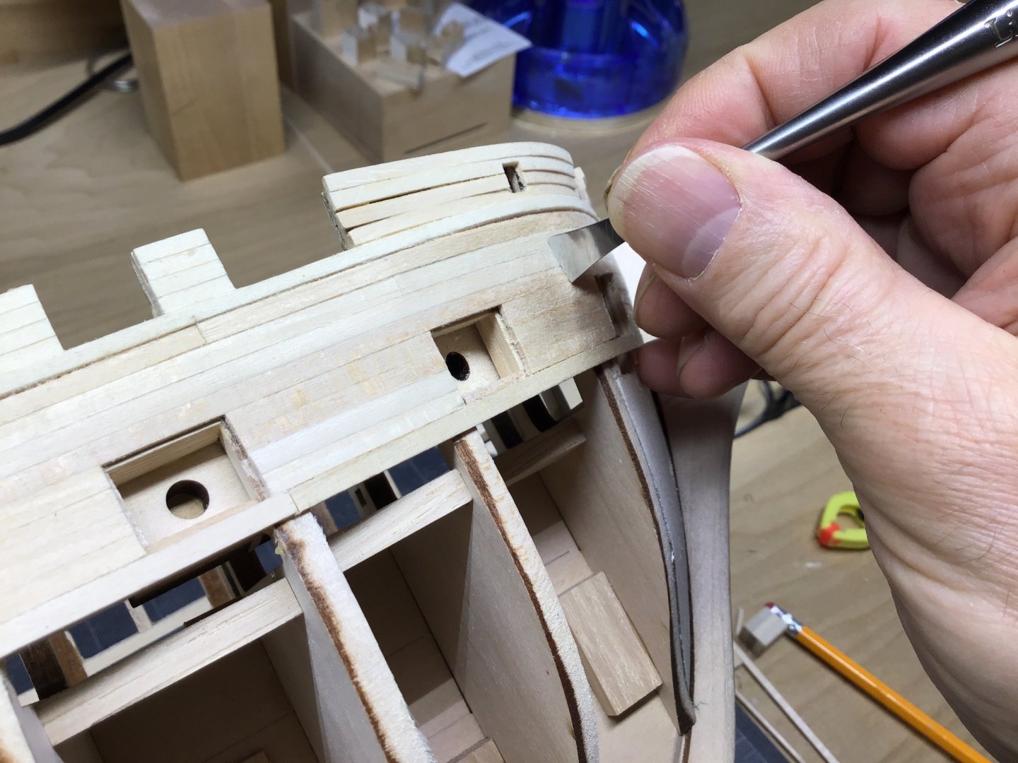
Smoothing the Planking Working on the starboard gun ports and planking is complete to the first full strake below the ports. Next step is smoothing the planks. Here the fishtail chisel is used as a scraper to lower the high spots. The chisel edge has a slight curve. This technique is useful for blending plank edges higher than their neighbor. And the pattern file is used to remove material right along the edge. Check progress by wiping the planks with a rag and alcohol - helps to get rid of the fuzzies. Working from the bow to stern, picture shows progress and work to be done. She’s a big model! I do want imperfections, to give the observer visual cues that the model is made of wood, and planked. Once built a model with a hull surface so smooth an observer that it was made of metal....


-
Hello J11, Thanks for the comment. One step at a time and learning on the way. First time building a multi deck/3 masted ship for me. Enjoy the springtime! Started work on the hatches and companionways - coamings specified in the kit as glued up strip wood but working on milling the rabbets in 7/32 x 5/32 stock. Stay tuned!
-
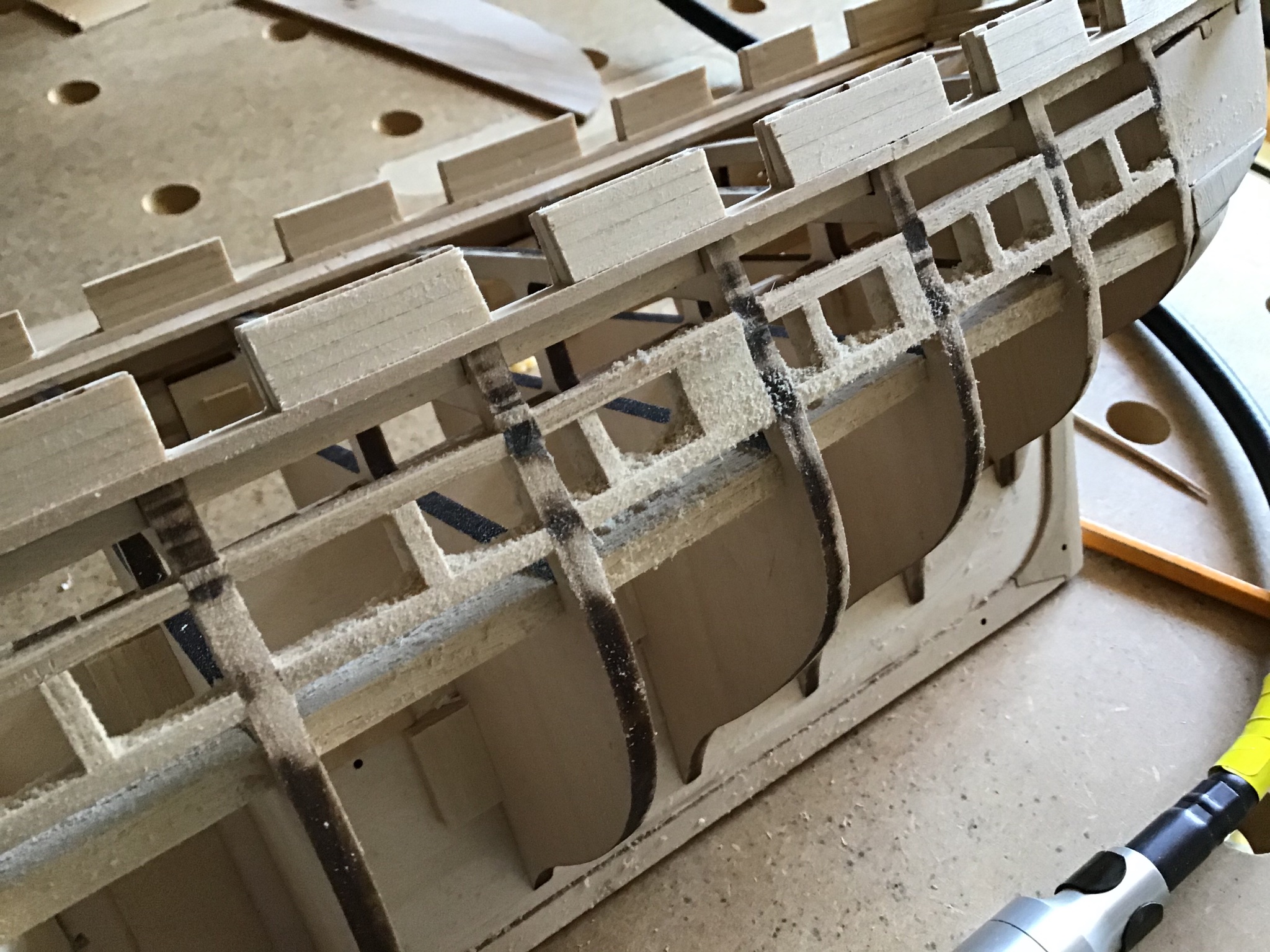
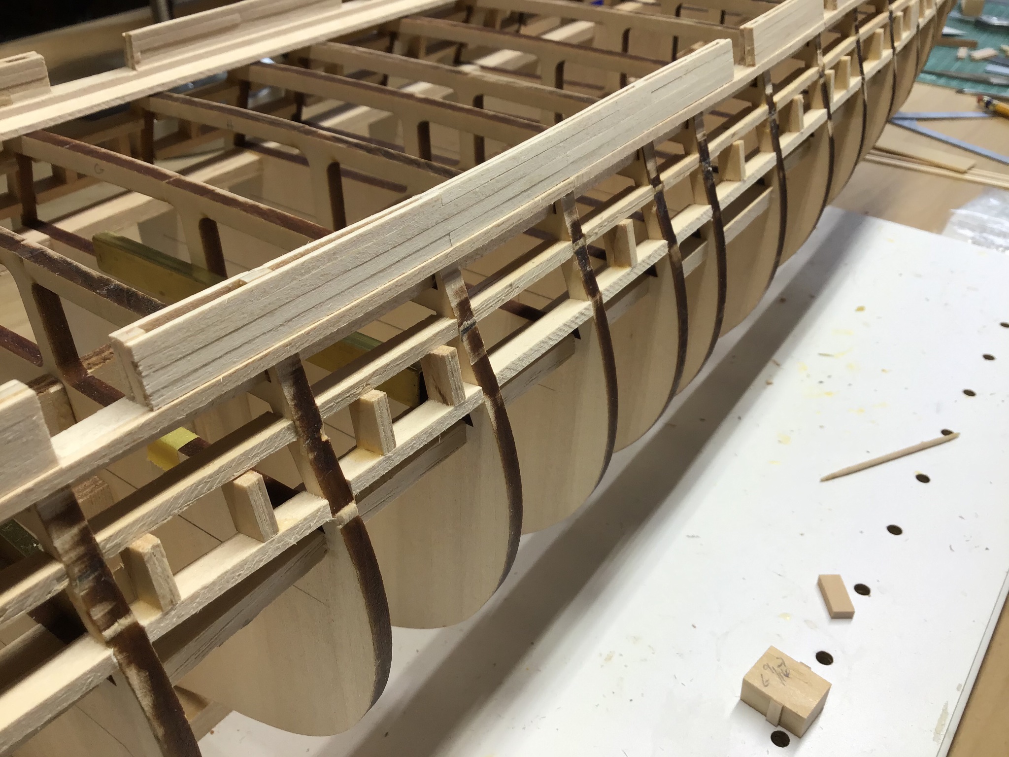
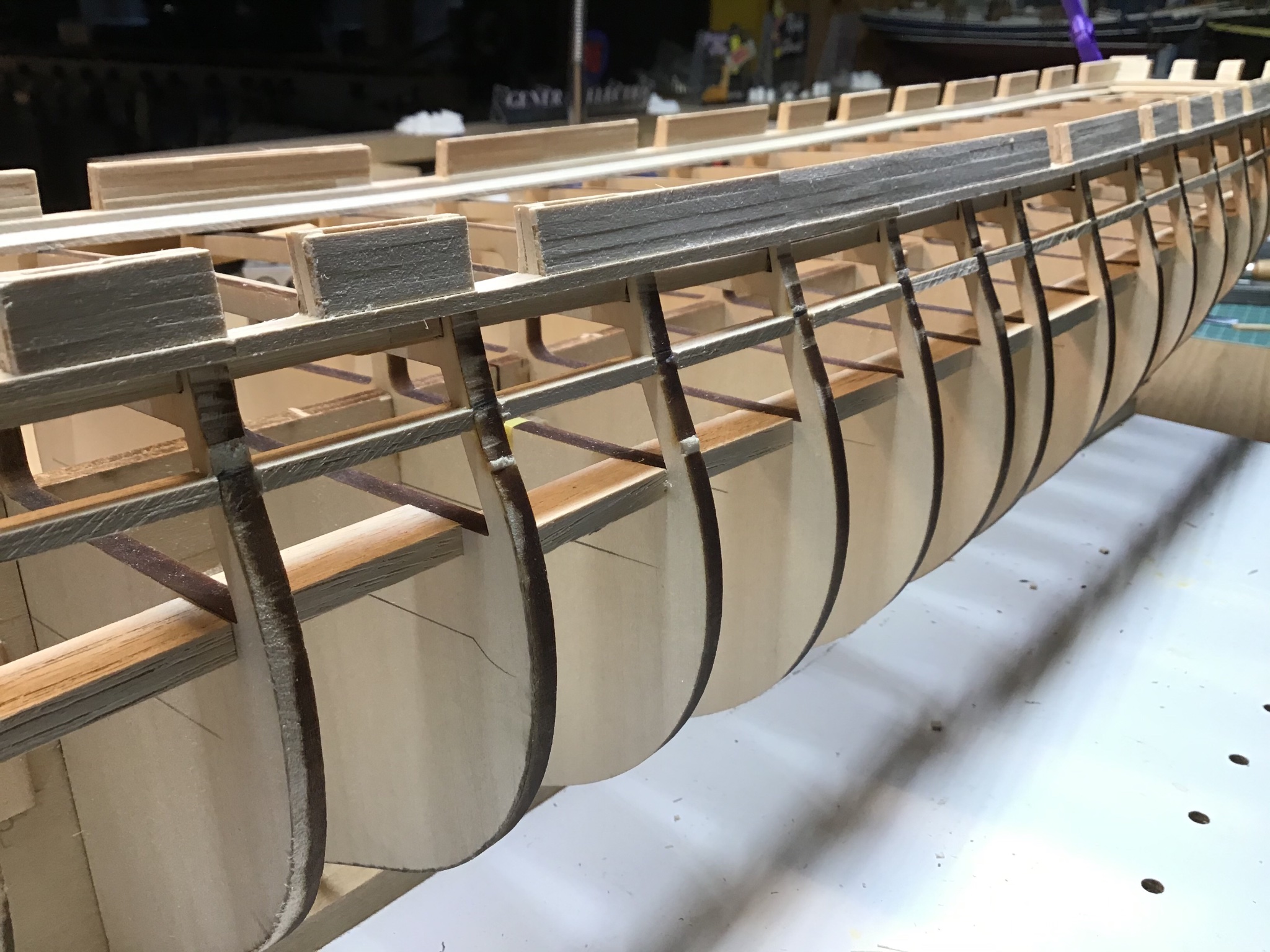
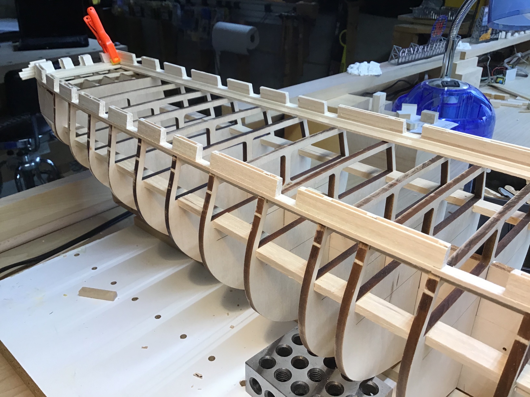
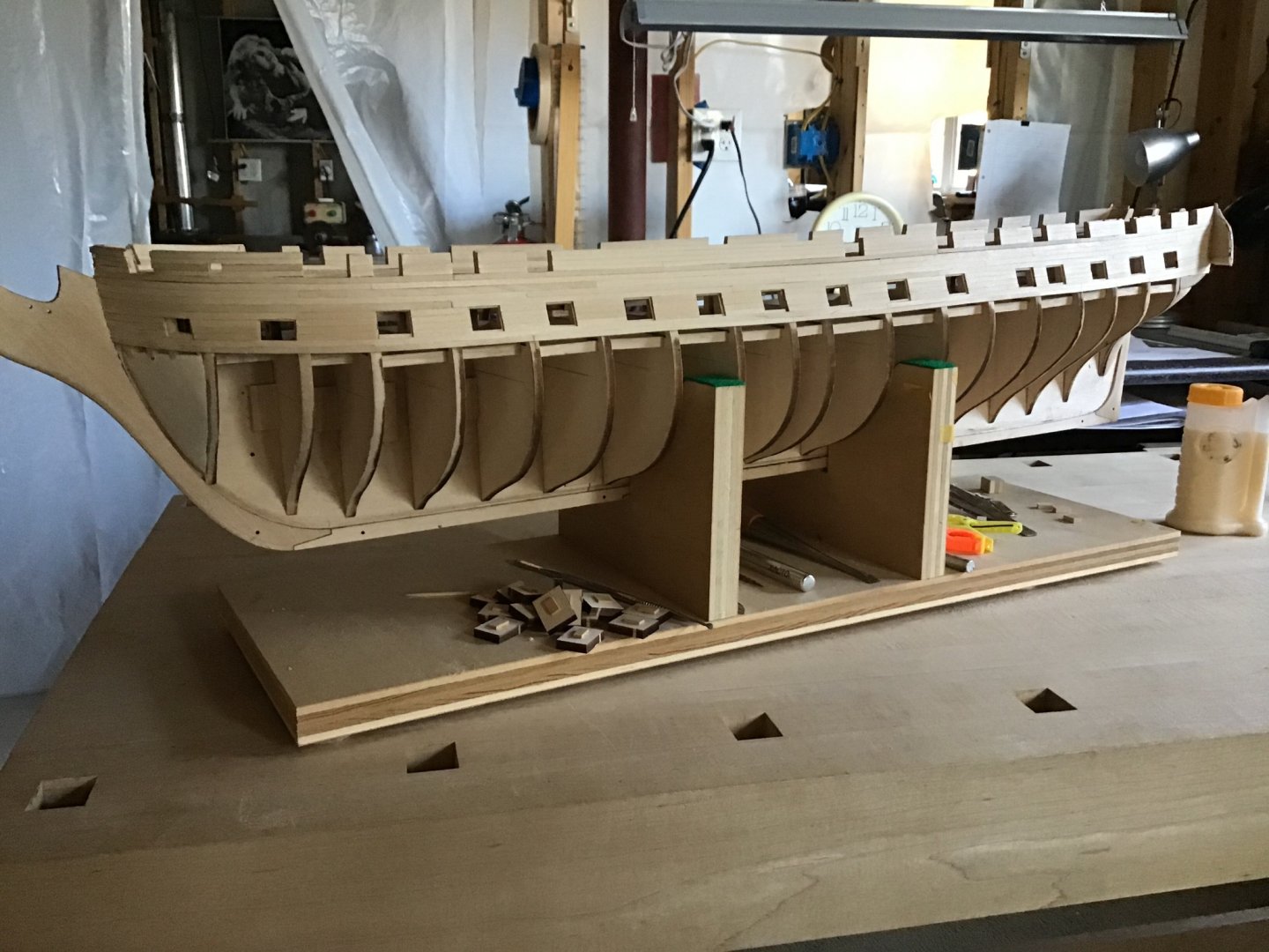
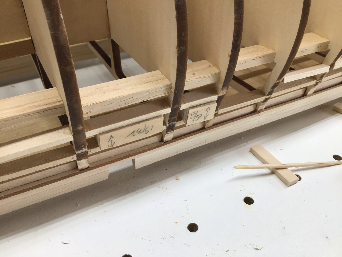
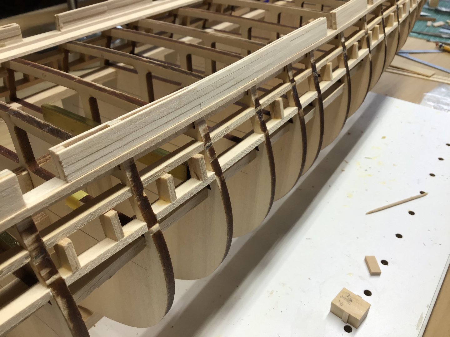
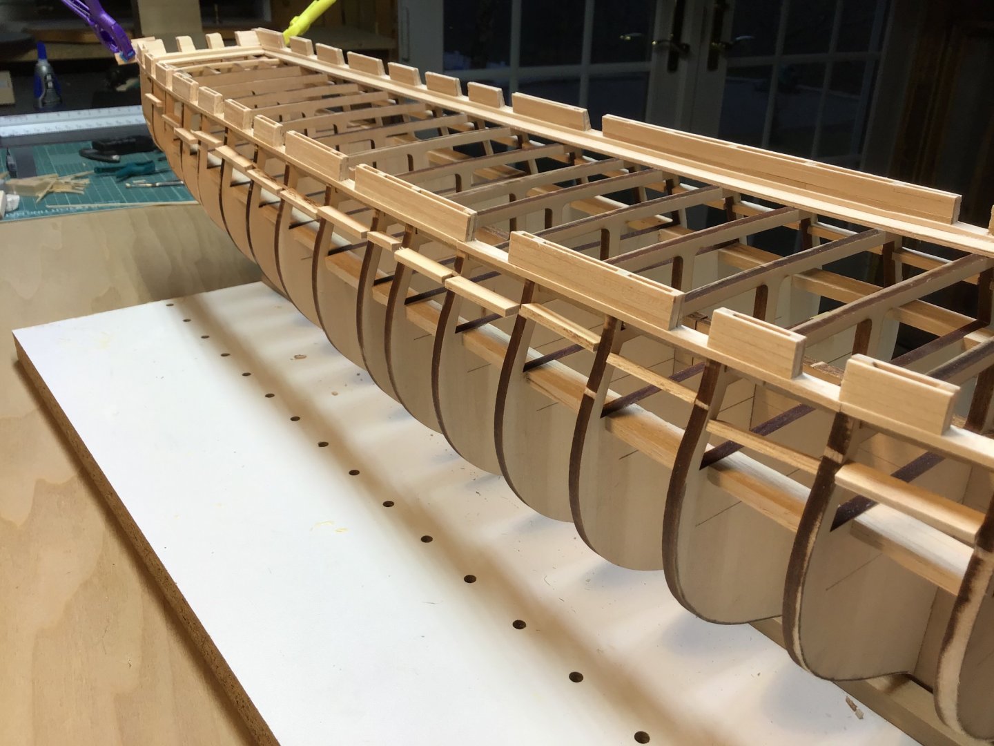
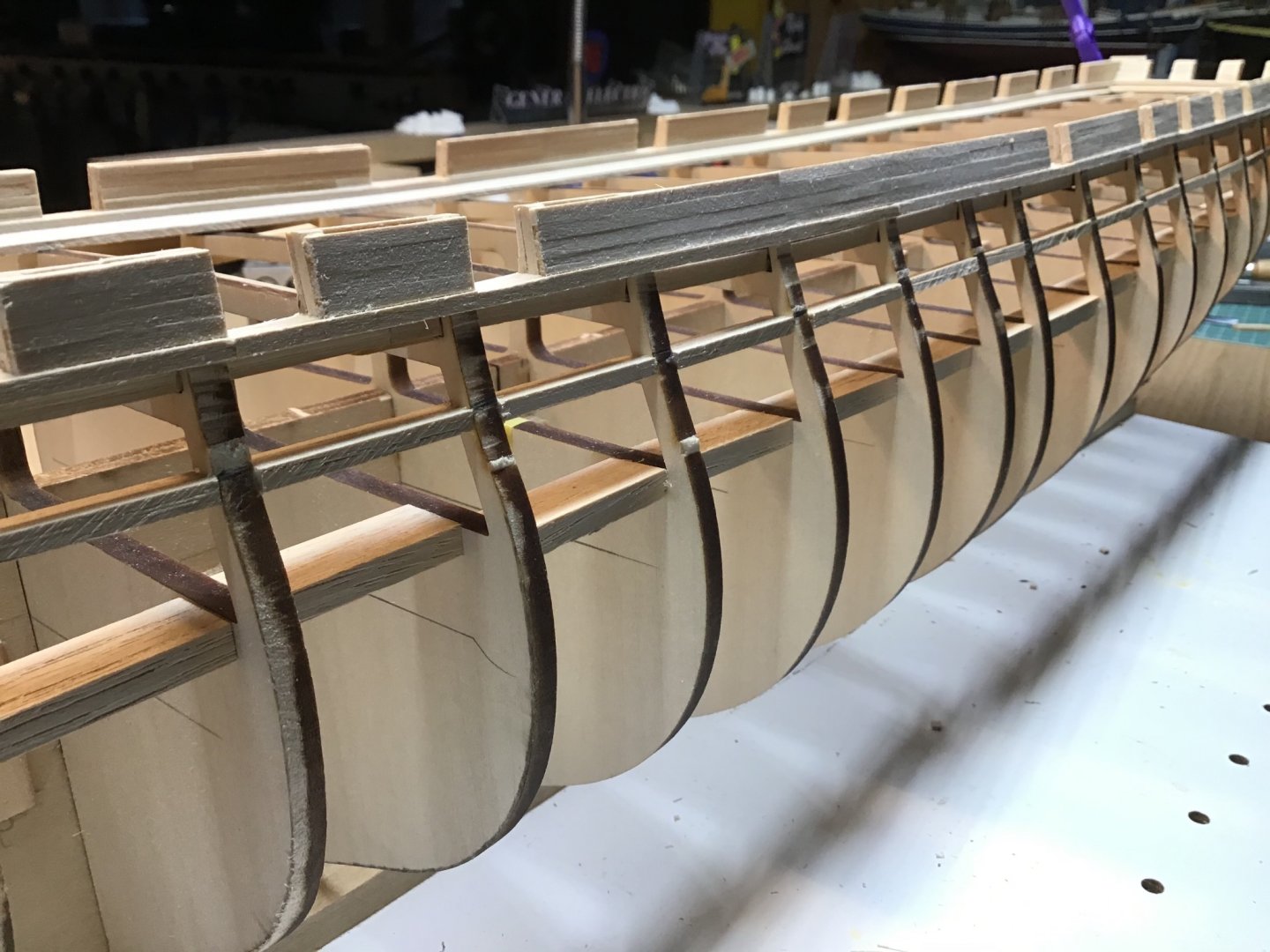
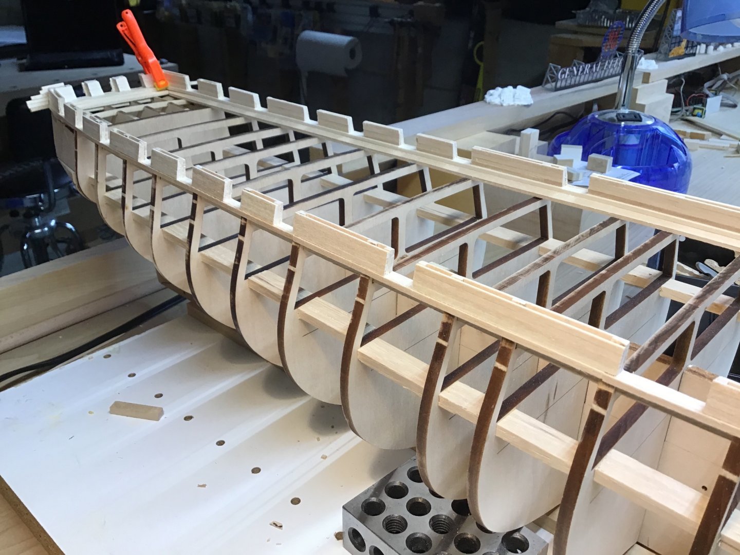
Lower Gunport Framing & Planking The lower sills were installed with 13/32” wide spacer blocks, height of the Gunport opening, against the upper sill. Next the side frames were cut on the table saw using the same spacer blocks to set the fence. The side frames were also aligned with a 9/16” block, which is the width of the Gunport. Wood tabs were glued to the Gunport backs to act as a backstop for the cannon. Planking 4 strakes down from the planksheer is straightforward. Planking ends 1/32” above the lower edge of the upper sill leaving a lip for the Gunport doors. Now is the time for final shaping/fairing of the bulkheads and the sills. Last photo shows blocks in Gunports with 1/32” stripping which establish the lip on the Gunport side frames during planking.

-
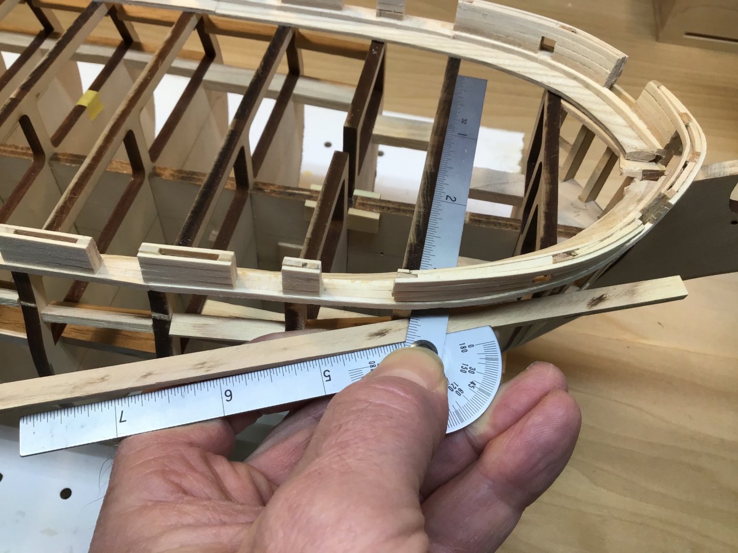
Lower Gunport Upper Sills Measured, cut, and dry fitted sills. Then glue and install in assembly line fashion. Used a spacer block 17/32” wide for uniform spacing from the bottom of the planksheer to the top of the sill. Sill between bulkheads A and B required a bevel cut, so used the protractor as a guide for marking the board. Aligned the mitre gauge by lining up the line on the board with the table saw slot edge. Last photo shows sills installed. They are the boards below the plank sheer.


-
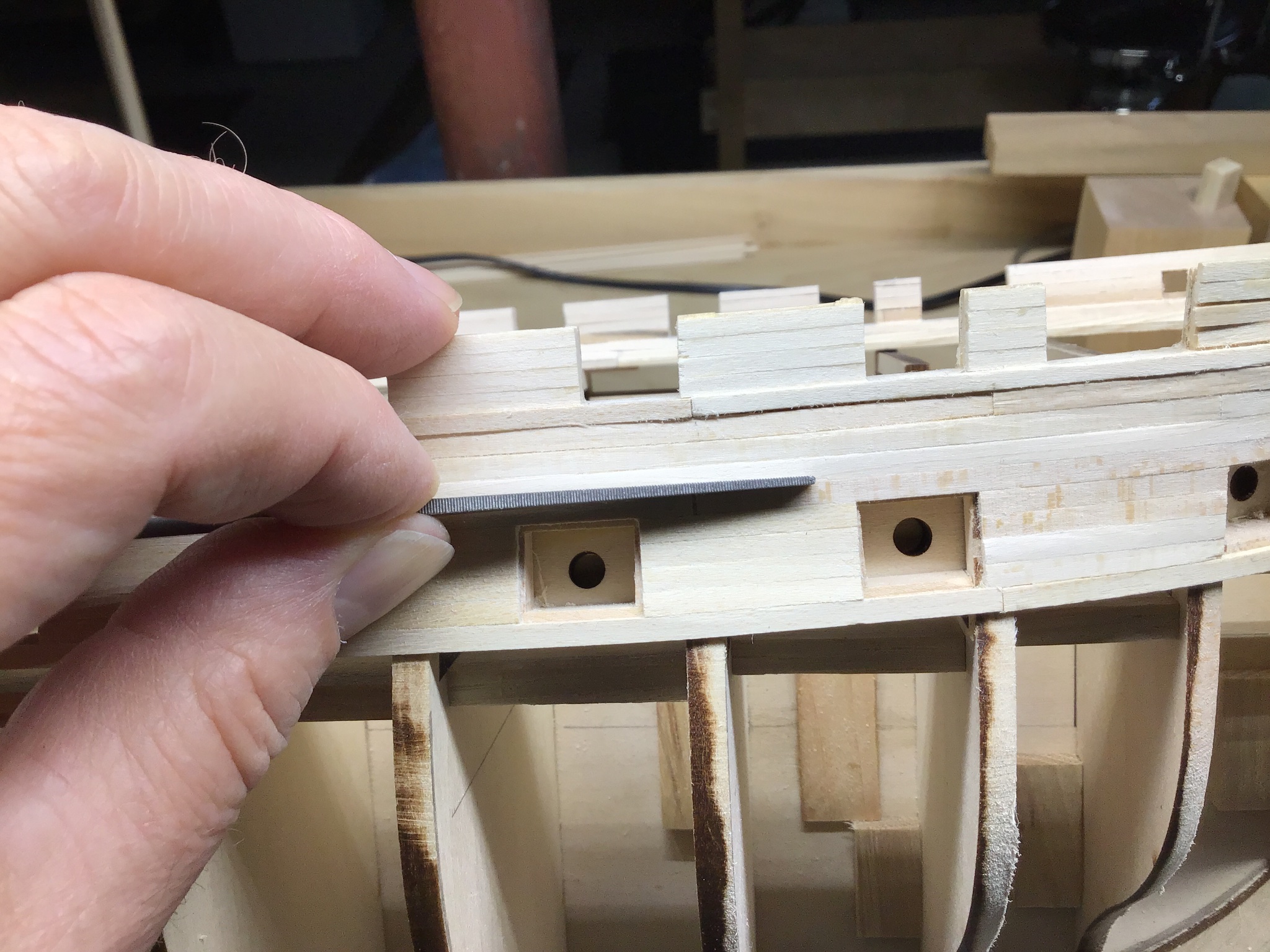
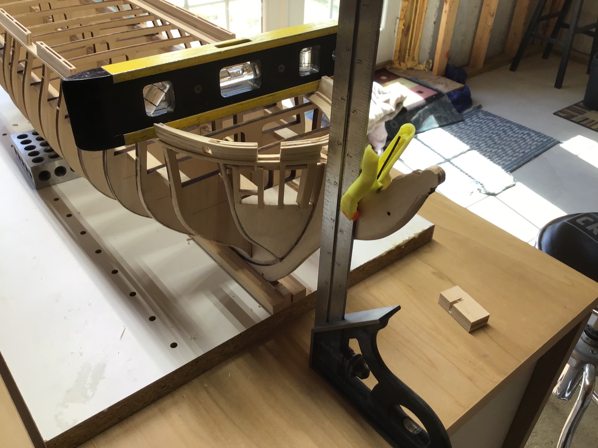
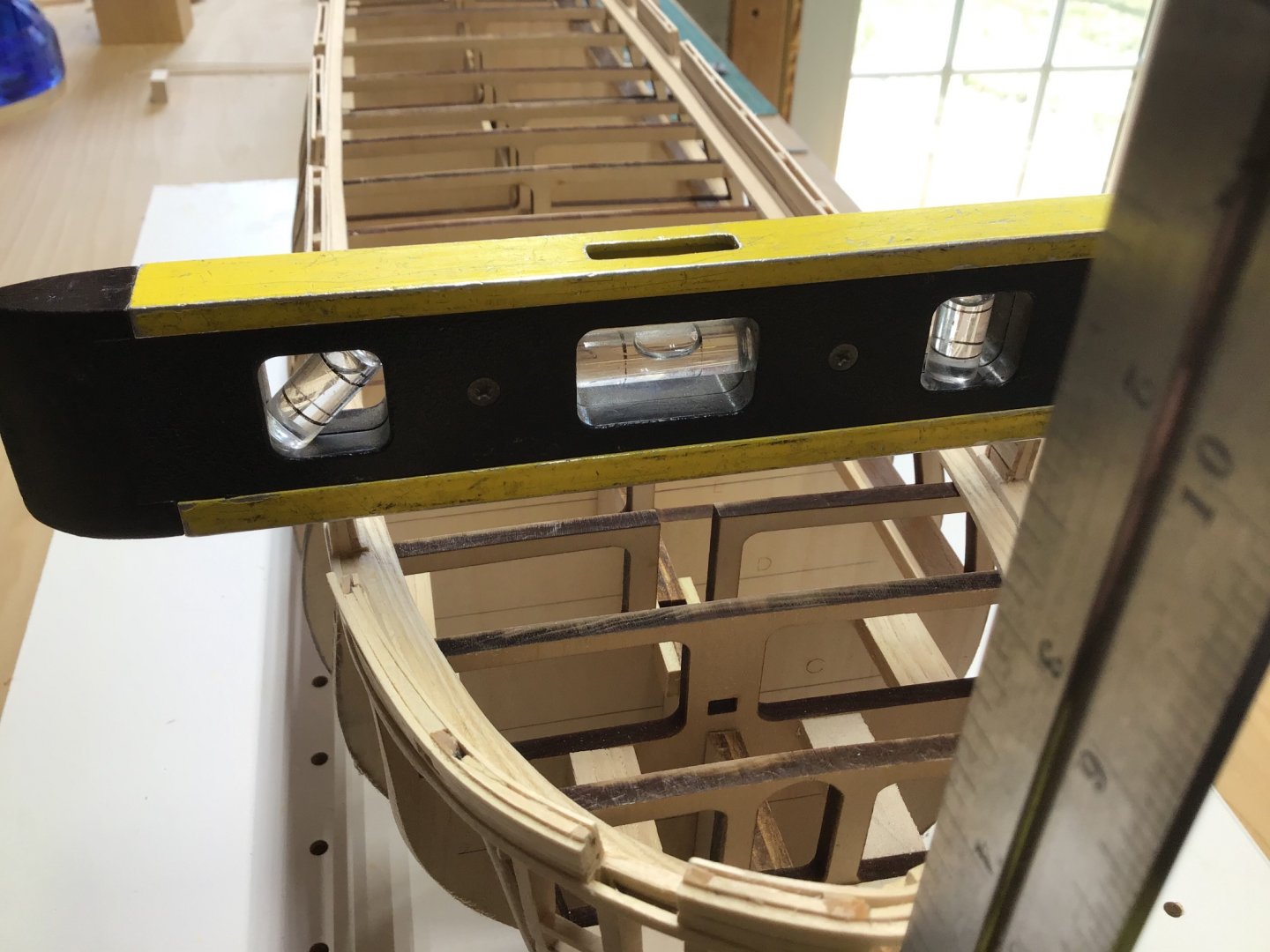
Leveling the Bulwarks Using this setup to level the heights of the bulwarks athwartship, port and starboard. First photo shows the combination square sitting on the bench top, with the stem clamped to it. My bench is level. The torpedo level shows the first set of sills are level. Second shot shows torpedo level on next set of bulwarks aft, and port side is a little high, so will file it down. And will proceed aft along the bulwarks and repeat.

-
Hello and welcome to the forum. I’m originally from Norristown and miss the pizza! Good luck with your first project. A ship with a single mast is a great place to start! Always around to answer a question.
-
Hello Reynard, welcome to the forum. Always available to answer a question. Have a great day.
-
2020 video showing Eagle Coastal Schooner and Baltimore Clipper near completion.
Galleries: Baltimore Clipper, Eagle
-
Hi, from an absolute rookie from Barcelona
ERS Rich replied to BCN-Modeller's topic in New member Introductions
Hello and greetings from Boston, USA. Always open to answering a question. Have fun and happy springtime! -
Hello, the paint, shading, and rope work is convincing. Sometimes I get tired of processing wood and your work shows there is an alternative. Thank you for taking the time to post. Have a good day.
- 222 replies
-
- 1
-

-
- reale de france
- heller
- (and 1 more)
-
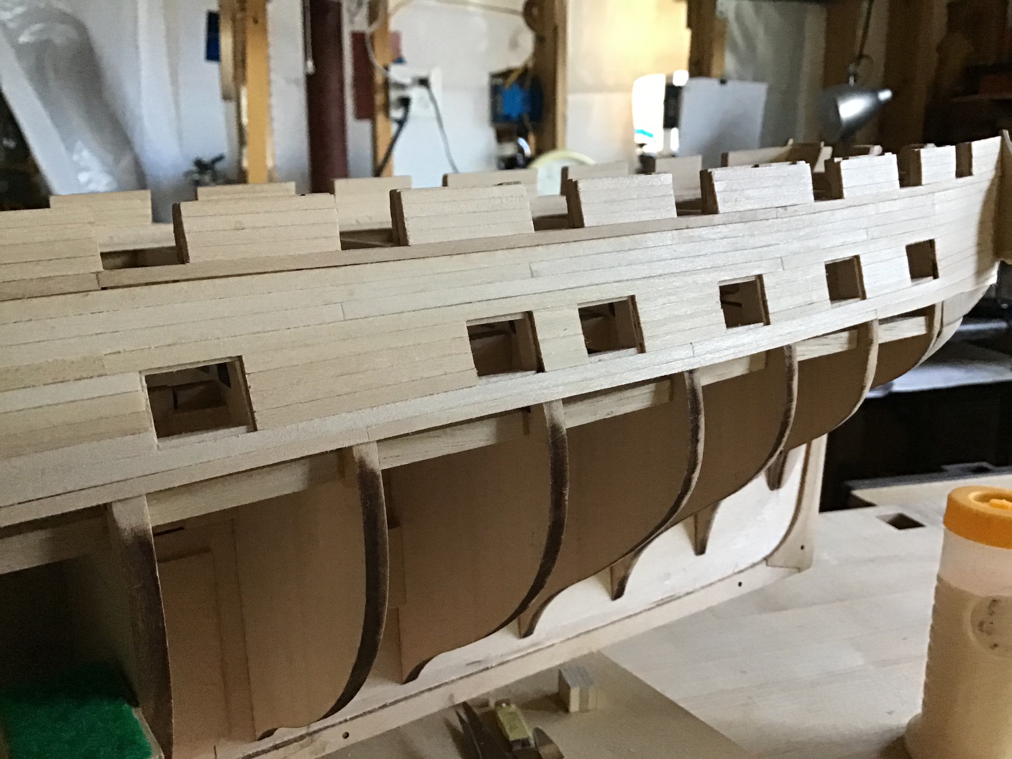
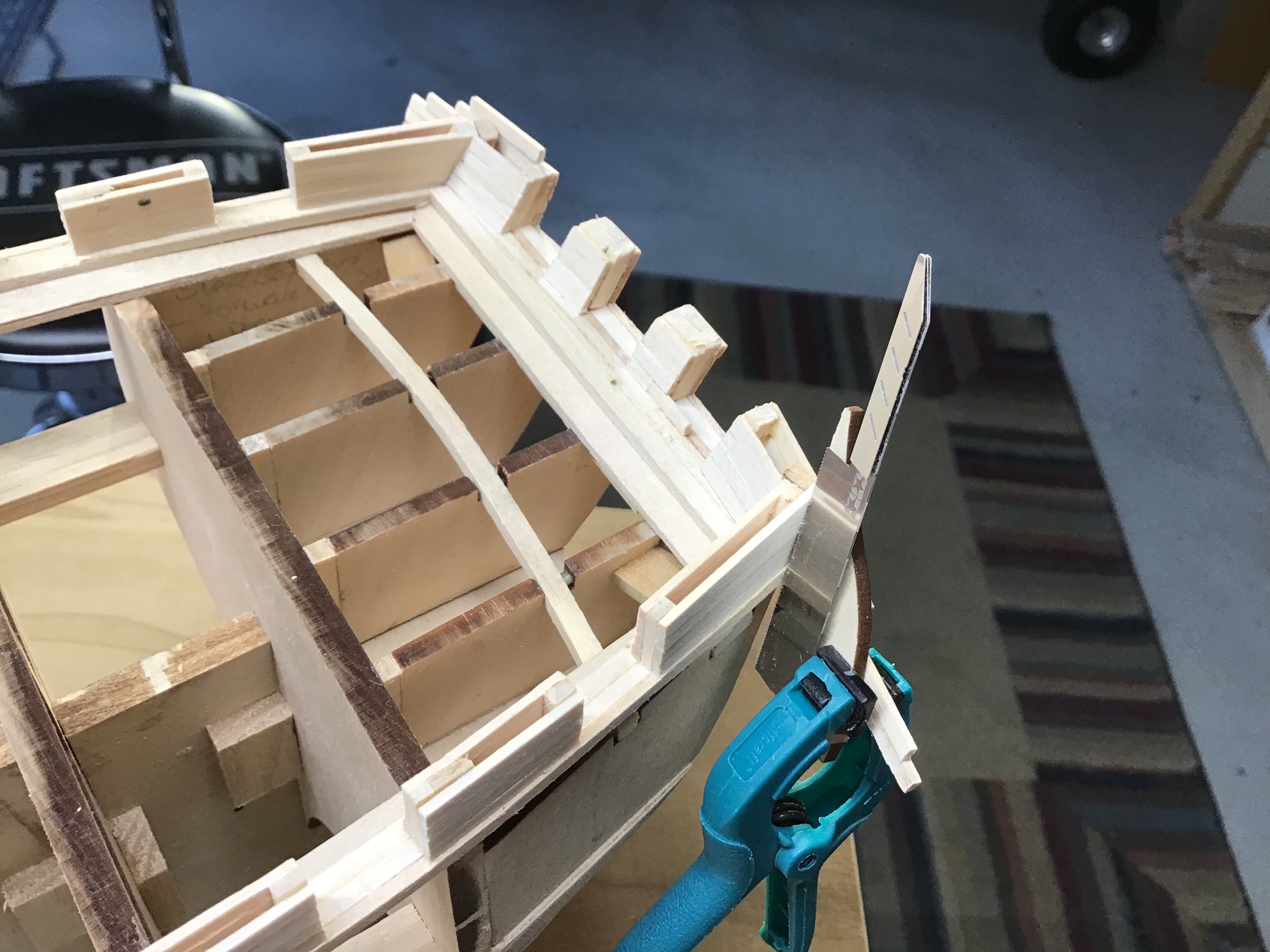
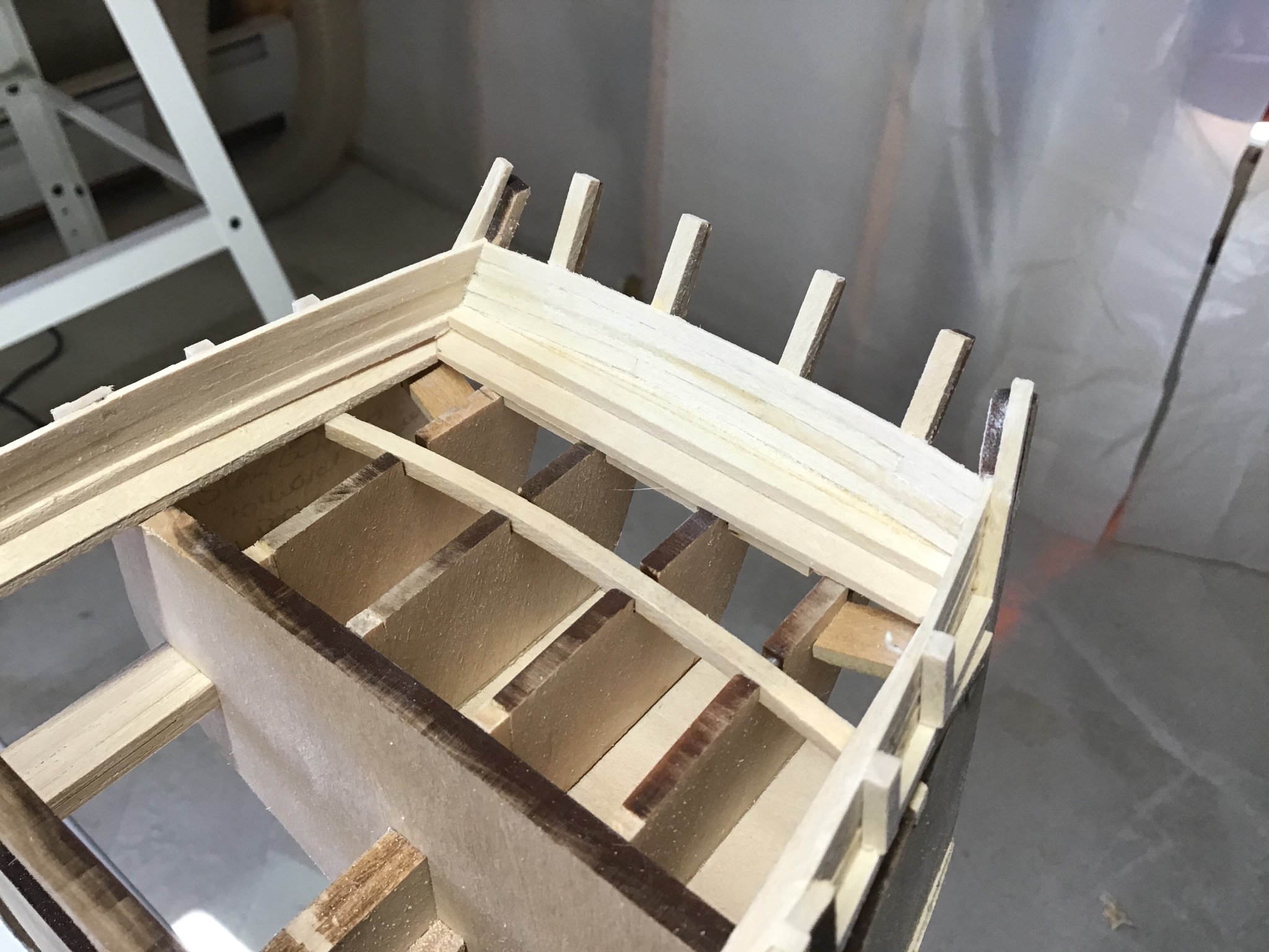
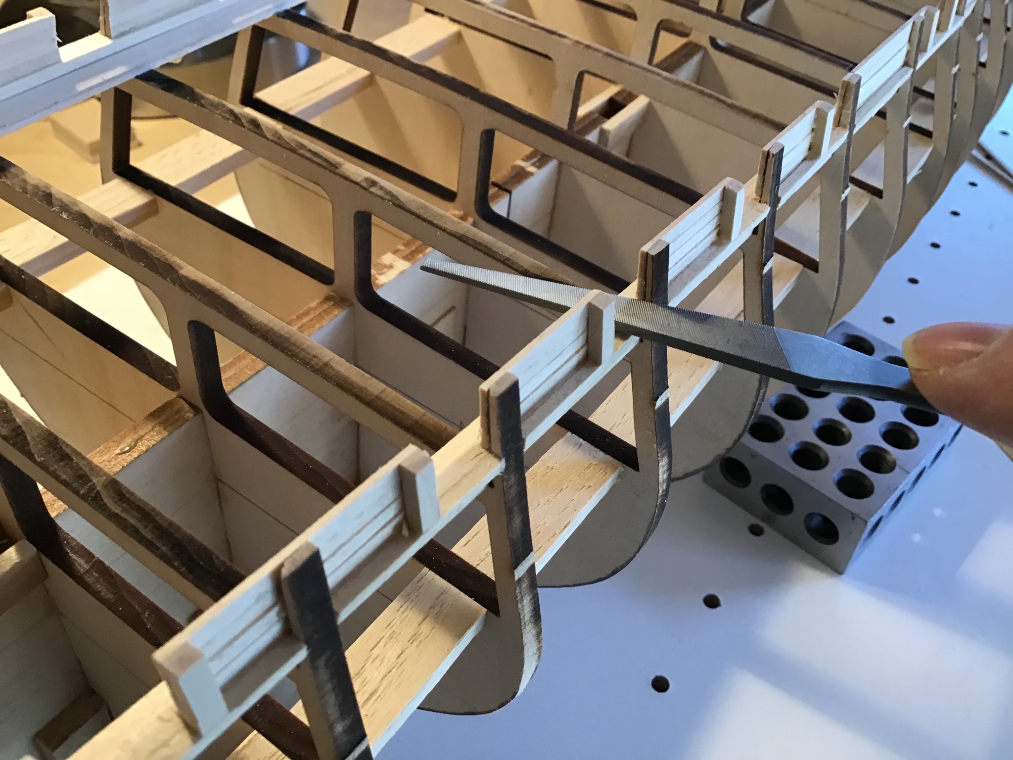
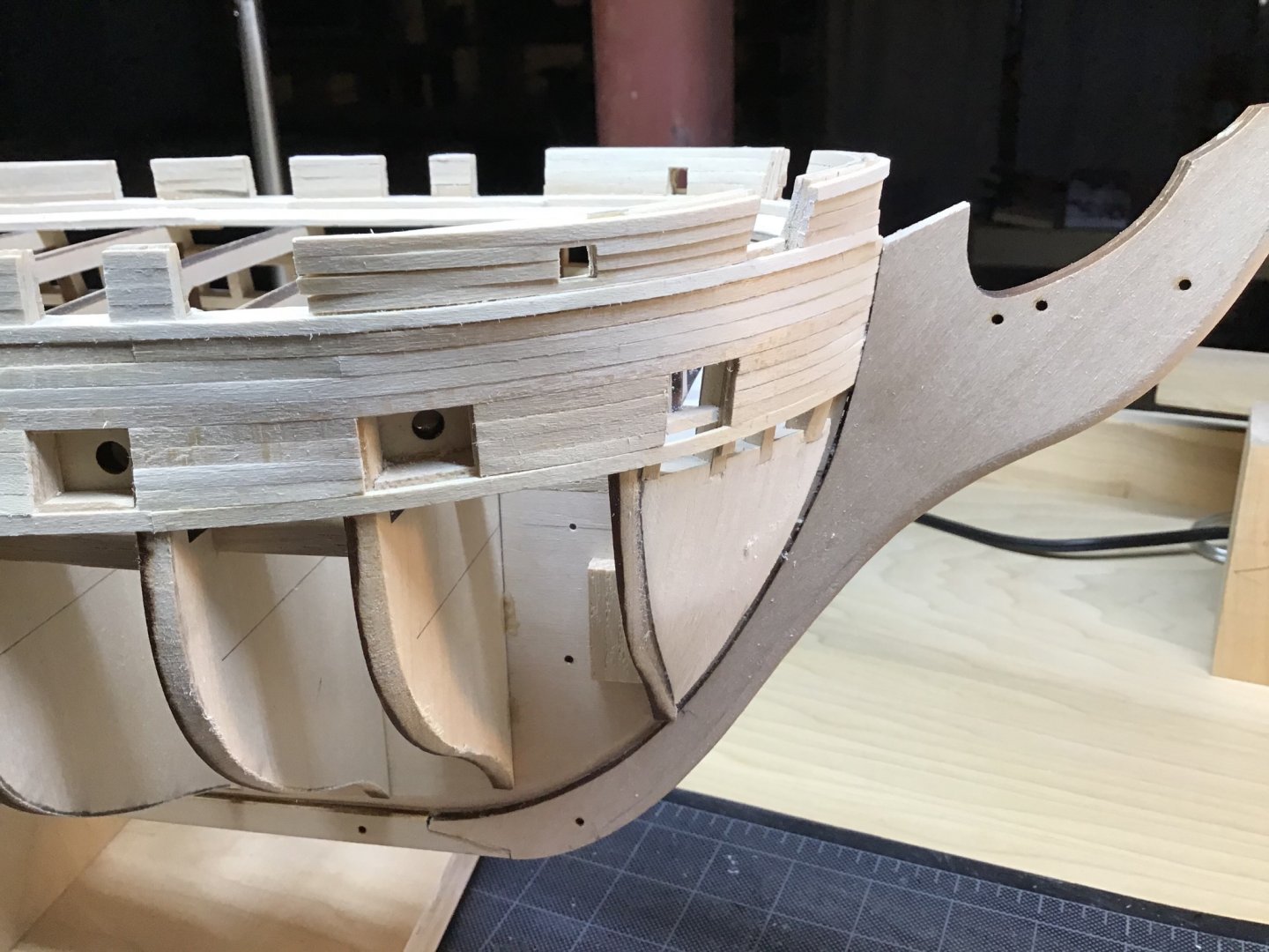
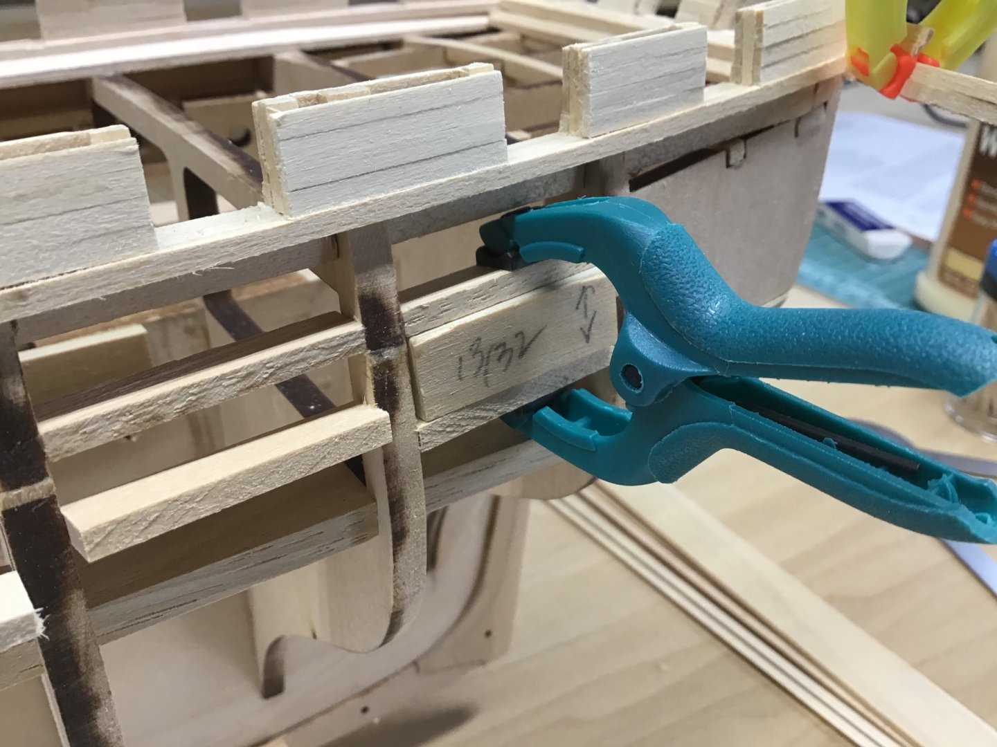
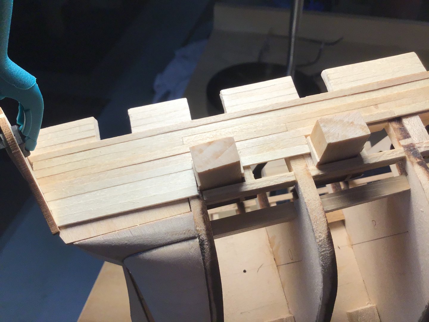
Bulwark Completion Wrapped up the bulwarks. Installed over 120 planks to complete the inside of the bulwarks. Methodology pretty simple. Measure width with the calipers and cut planks with the Byrnes saw. Used the pattern file to smooth the gun port edges. Also laid the file across the sills, from side to side, to even the sills. See second photo. At the bow it was time to fair the bulkhead extensions. Essential to steam bend the bow bulwark planking. Spent some time thinking about the stern bulwark planking and the port and starboard counter extensions. To get the correct angle, made the planks extra long, clamped the extensions to the planks, then used the mini saw to cutout the ends of the bulwark planks and the planksheer. See the photo with the blue clamp. Along the way cutout the openings for the catheads. Cut inside opening first after framing, then planked over the outside, and cut inside out. Little holes are visible, from drilling to get started with removing the waste from the opening. Overall I’m happy with the result, however found I made a mistake as the planksheer port and starboard side aft are out of alignment vertically a little less than a 1/16”. I think it will be covered by the stern galleries.


-
This looking nice....now the USS Perry, no longer the USS Putty! Cheers!
- 85 replies
-
- 2
-
-
- perry
- BlueJacket Shipcrafters
- (and 1 more)
-
Hello, a really nice ship model. I like the look and feel overall and the deck in particular. Enjoy your rides, still a little early, but today is a warm day in Massachusetts. We’ll be riding soon. Have this kit on the shelf and will use your work for guidance. Thanks for posting.
-
Hello, greetings from Massachusetts! Welcome aboard and I’m always open to answering a question. Cheers!
-
Greetings from Boston USA, Stereo microscope! Wow! Thank you for showing how it’s done. Would you happen to know where one could purchase a Jewelers Lathe? Cheers
-
Final coat of furniture paste wax is also an option....easy to apply, ready quickly, a traditional wood finish, looks good.... Coating wood with plastic, that’s what poly is, seems incongruous with a ship model, and I hate the hazardous waste.... My personal preference is shellac or stain under acrylics (painted finish) or stain/wax (unpainted finish). Cheers
-
Hello, When shipbuilding in all things, I pick the color that appeals to me.... One of my professions is cabinet making, so based on my work with pine, 1 or 2 look ok.... And we know in real life, based on the finish, how old it is, and how well it’s maintained there is no one true mast color.... Therefore I just pick what makes sense to me.... Thank you.
-
1 or 2 look good to me....however in life the color variations are infinite.... Cheers
-
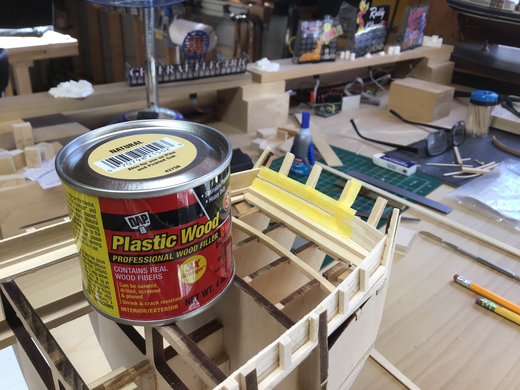
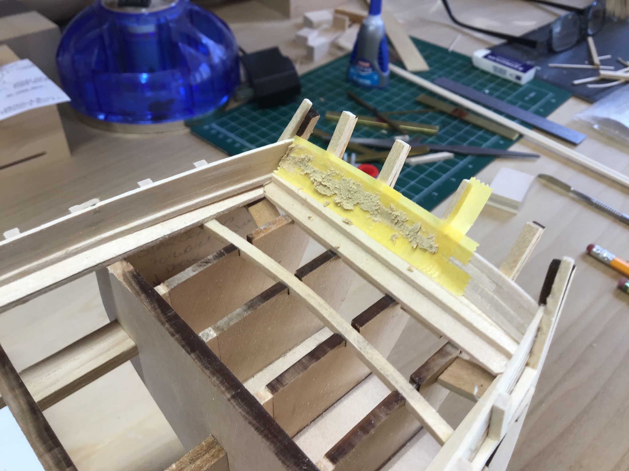
Gun Port Cleanup and Bulwark Prep Some gaps to fill in the bulwarks. I avoid sanding whenever possible. Mask the area. Fill with plastic wood. Peel masking tape before drying. Remove chunks with chisel and smooth with sandpaper. Last few ports were cut with a Tamiya mini saw. I like to chisel for the practice, however, going forward will use the mini saws. Pattern file used to smooth gun port sides and sill. Safe sides are helpful. Tip: when working the gun port sides, cut and file from the inside out to avoid tearing the wood fibers on the bulwark board ends. Tamiya razor saw used to cutoff extensions.