HOLIDAY DONATION DRIVE - SUPPORT MSW - DO YOUR PART TO KEEP THIS GREAT FORUM GOING! (Only 24 donations so far out of 49,000 members - C'mon guys!)
×


DocBlake
-
Posts
1,811 -
Joined
-
Last visited
Content Type
Profiles
Forums
Gallery
Events
Everything posted by DocBlake
-
 Very nice, Greg. Everything looks great. Your planking turned out well. If there are errors, only you will see them! Good job!
 -
Beautiful job, Tony. Really inspiring!
- 132 replies
-
- 3
-

-
- triton cross-section
- cross-section
- (and 1 more)
-
Thanks, Pete! The frames are rough, glued up after the parts were cut on the scroll saw. No sanding yet! I need to make a building jig next. As I mentioned earlier, the top timbers do not form a rectangle in plan view but rather taper on slightly both for and aft. Any tricks as to how to lay that out? Second question: Should the futtocks be fastened with treenails or historically more accurate simulated bolts?
-
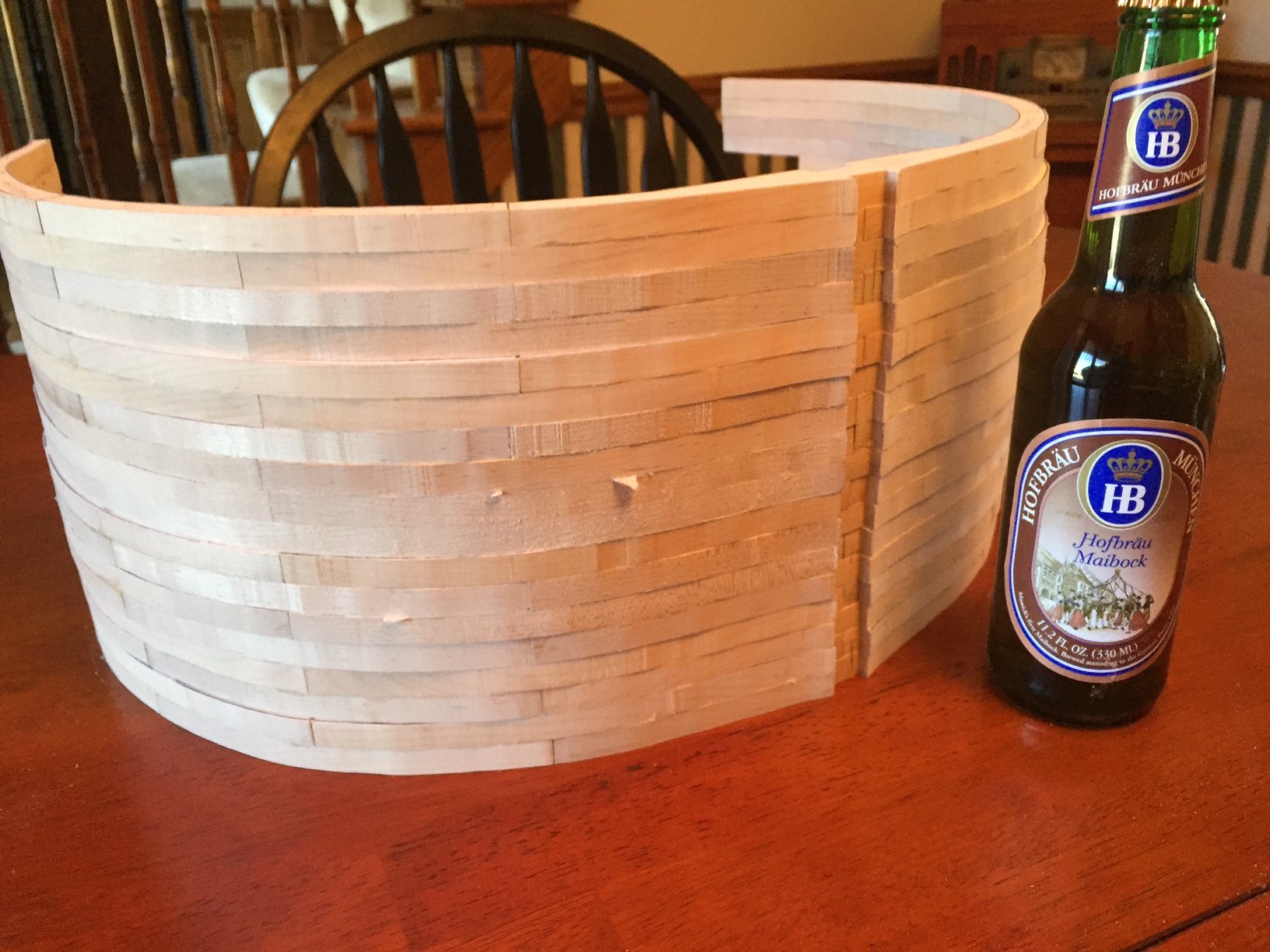
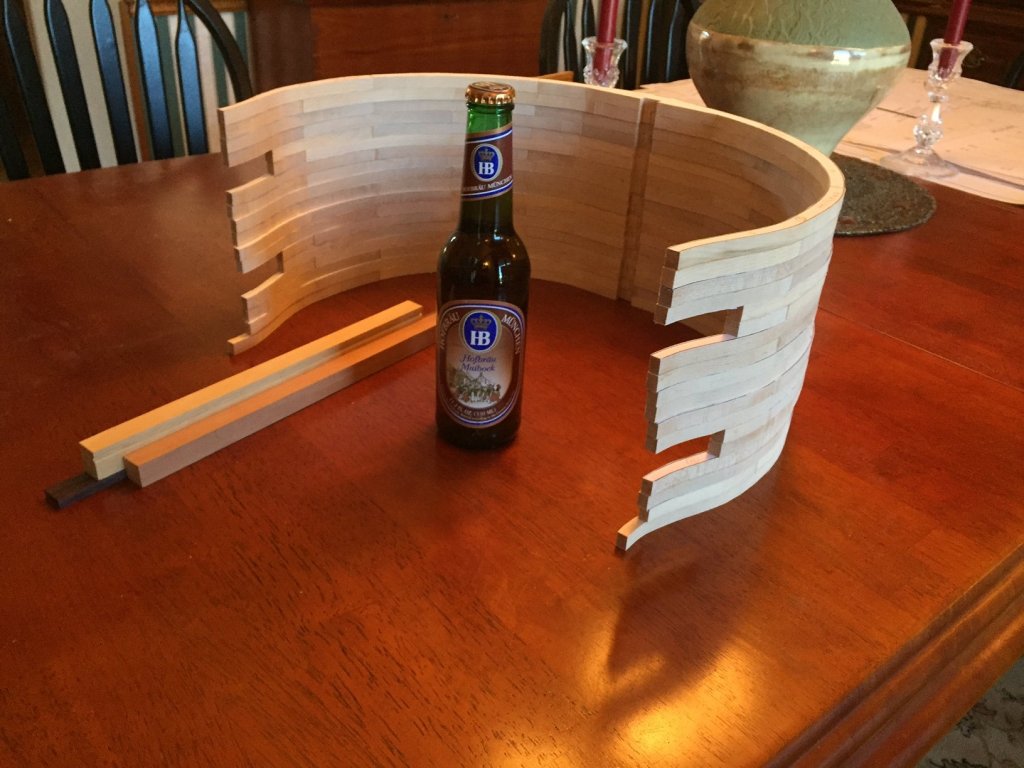
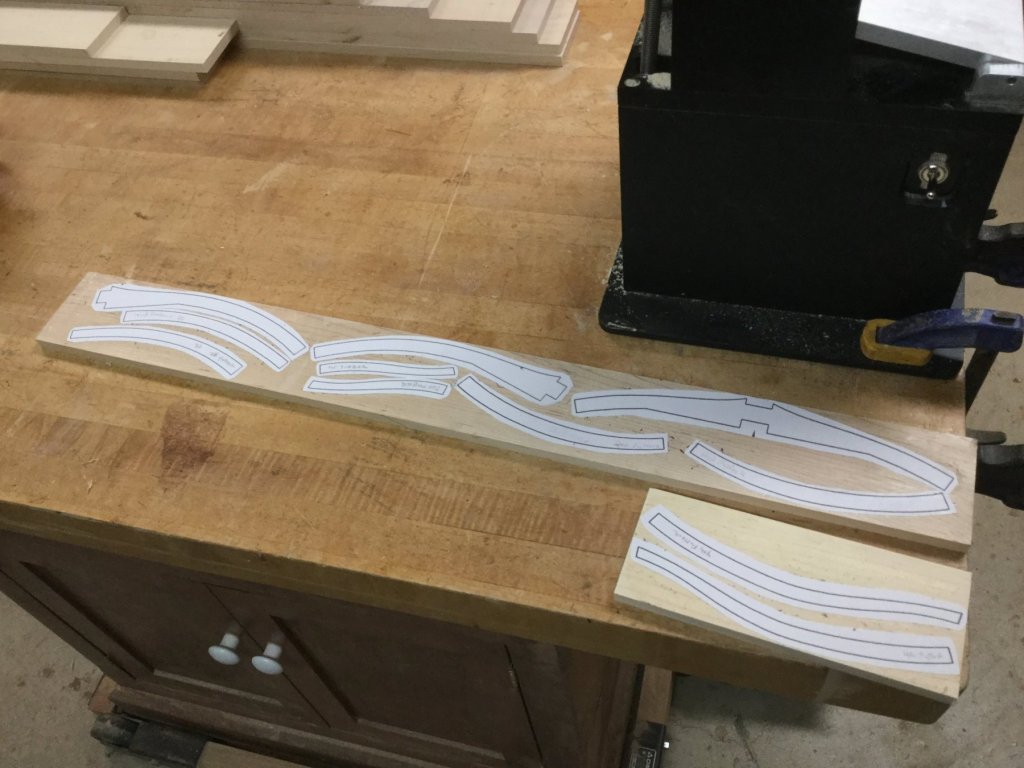
I finished gluing up the last of the 9 frames. I used Weldbond so I'll give the most recently completed frames a couple of days to dry before rough handling. The frames will require minimal trimming and shimming in a few spots to conform to the plans. Once that's done, I'll rough sand the frames to match the plans and start to glue and dowel then to the keel. It took one week to enlarge the plans, glue up the individual futtock on to the billets, cut them out and glue them together. I used double sided tape to hold the appropriate futtocks to the plans and glued the second layer to the first. taped down layer. I put a piece of plywood weighted with big food cans to weight down the plywood until they dried. The beer is to celebrate! It's a Hofbrau Maibock.

-
As I continue cutting out and gluing up futtocks I'm thinking ahead. Should I use simulated bolts (historically accurate) to hold the frames together, or treenails, which may be esthetically more pleasing?
-
I wish I'd learned CAD! Thanks, guys. I think I can muddle through. I'm not too worried about the thickness of the frames but rather the height of the top timbers where a little shimming may be needed before fitting the rails.
-
I've glued up 5 of the 9 frames and I'm noticing some "tolerance creep". When I enlarge the frame parts to 200%, the lines outlining the parts get some real thickness to them: 1/32" - 3/64"). This is especially a problem where the frames butt each other. They need to be accurate or the frame doesn't match the plans, and things like gun port lintels and sills are thrown off. I've already noticed some slight inconsistencies as I glue up the frames. They are not matching 100% and on both sides of the frame. The errors are small...in the range of 1/32", but they are there. Hopefully I can figure out a fix when the time comes. Very thin shims will likely be the answer for any frame component too short at the top timbers, with trimming if they are slightly long. This problem is a function of the large scale of the model (1/24). Has anyone else encountered this problem?
-
Great tutorial, Don! And continuing great work on the model. BTW: Before the switch in software, MSW "content I follow" always listed the latest comment on a topic first, with the other comments on other topics chronologically in order. You were always able to keep up with the latest developments. With the current setup, that's not the case. Despite the post above mine (Mike's) posted 14 hours ago, this build log and it's latest post remain on page 5 of my "content I follow" menu. Can that be fixed? Anyone know?
- 653 replies
-
- 4
-
-
- trabakul
- marisstella
- (and 1 more)
-
Tony, I think the Triton area has been re-opened to new builders once again. Access to the build files is available after producing a keel, false keel and keelsonas it had been..
- 132 replies
-
- 3
-
-
- triton cross-section
- cross-section
- (and 1 more)
-
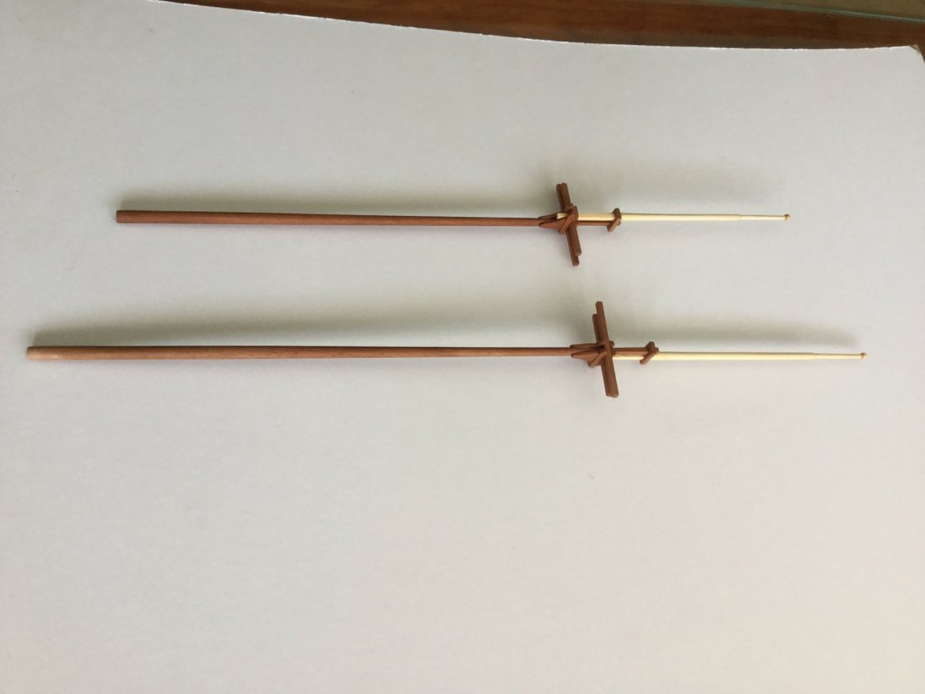
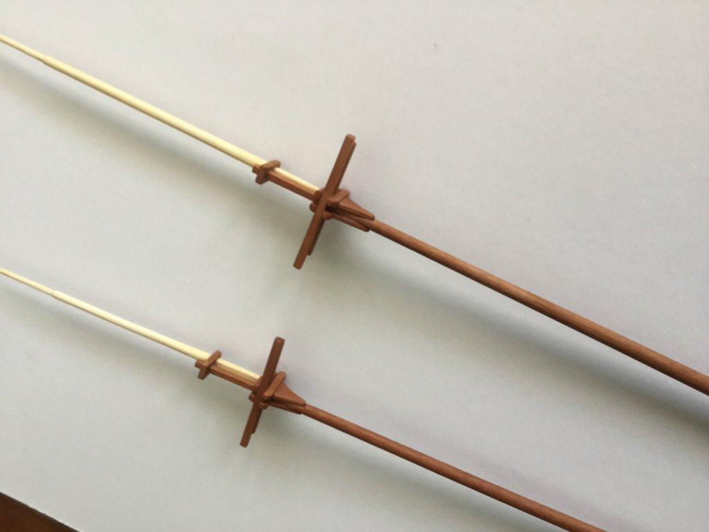
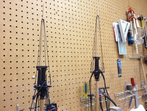
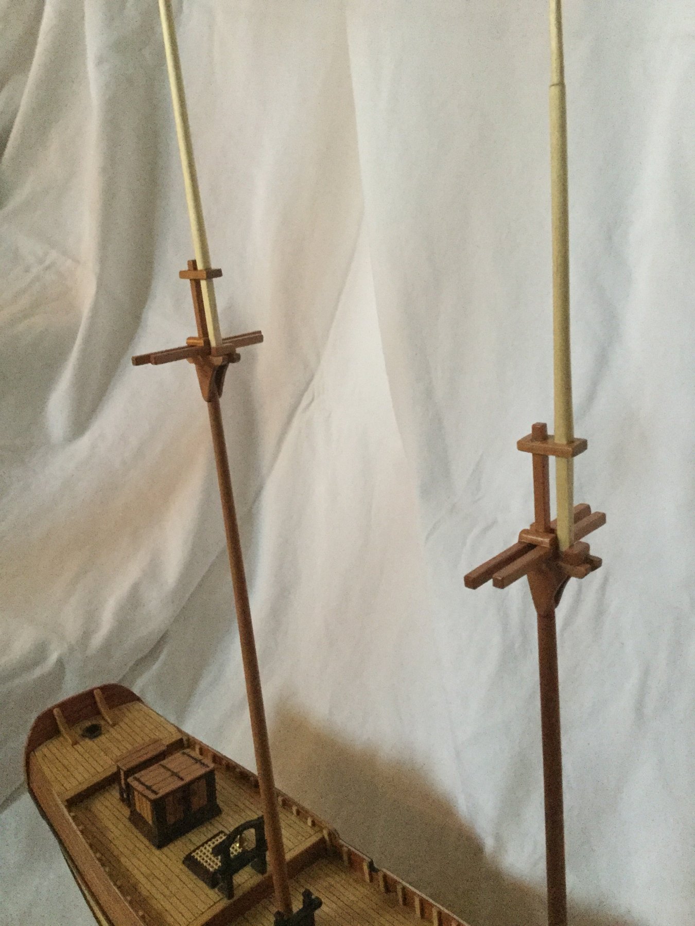
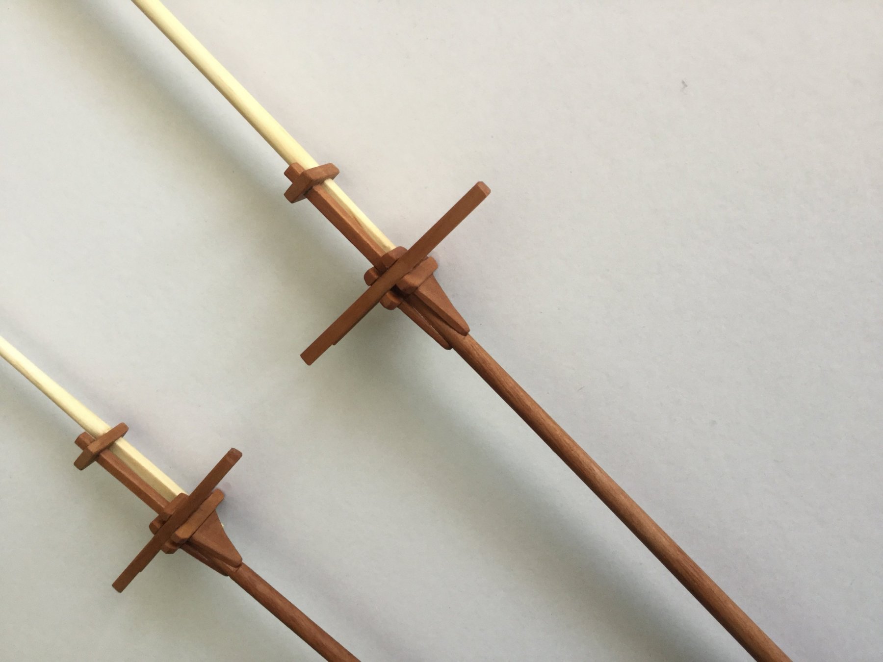
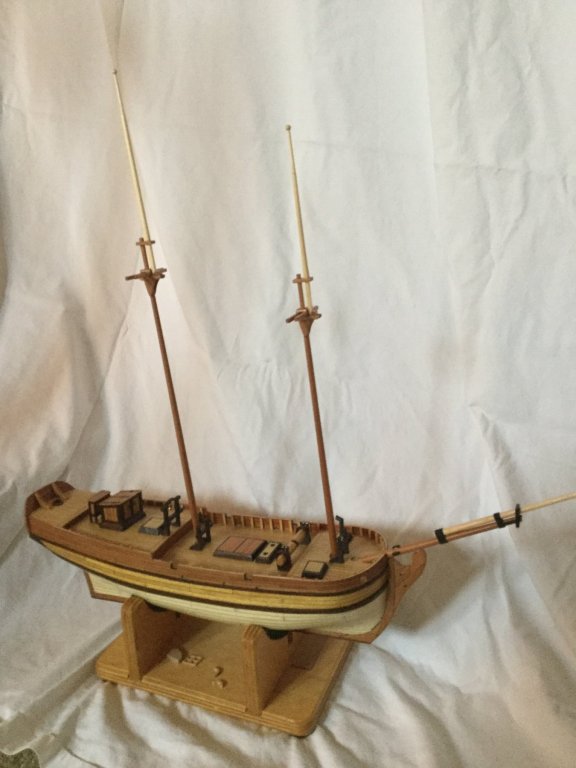
The masts and sprit are done except for the boom rests. Rigging soon!
-
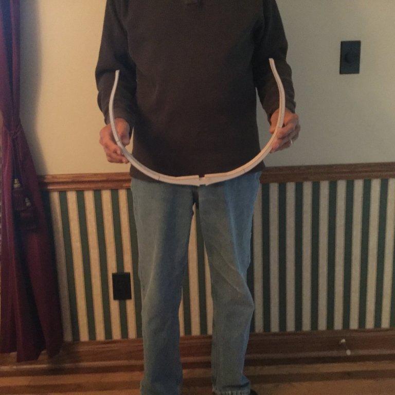
You are right Brian! When I measured the footprint I measured between the top timbers. The tumblehome gave the smaller measurement. The beam is really 16-3/4". It will be a big model! The Admiral would probably not agree about me being a "twig".
-
Thanks, Eddie. Milestone! The first frame is glued up. I'll finish all nine before rough sanding them.
-
I laid out the futtocks for frame #1 on the billets. There are 11 parts per double frame and 9 frames in all. I'll glue up frame #1 today and cut out frame #2 also.

-
I love the companion way (well, everything really!). The model's stand is also outstanding. Great work, Don.
- 653 replies
-
- 6
-
-
- trabakul
- marisstella
- (and 1 more)
-
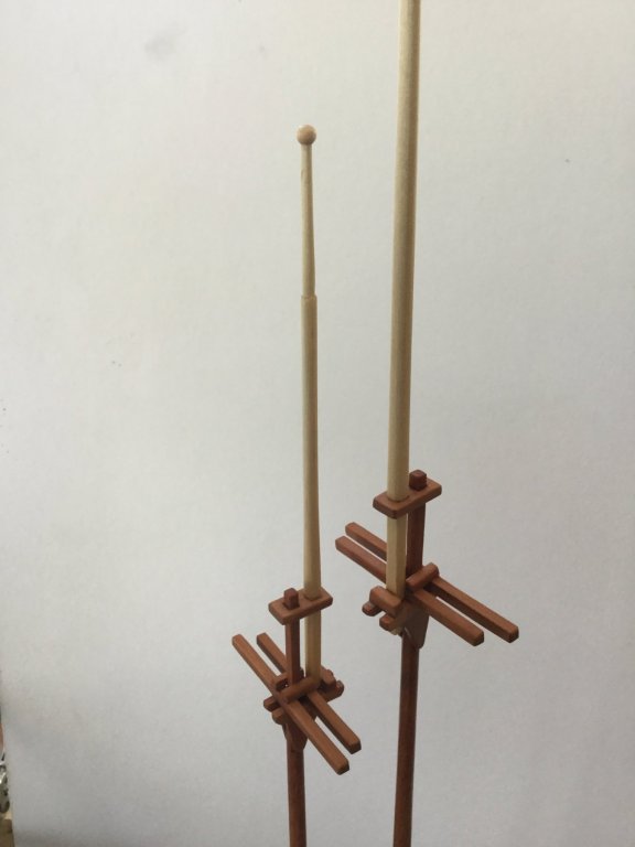
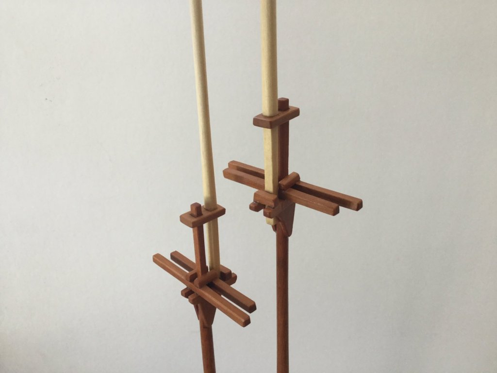
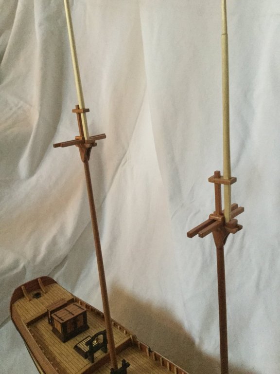
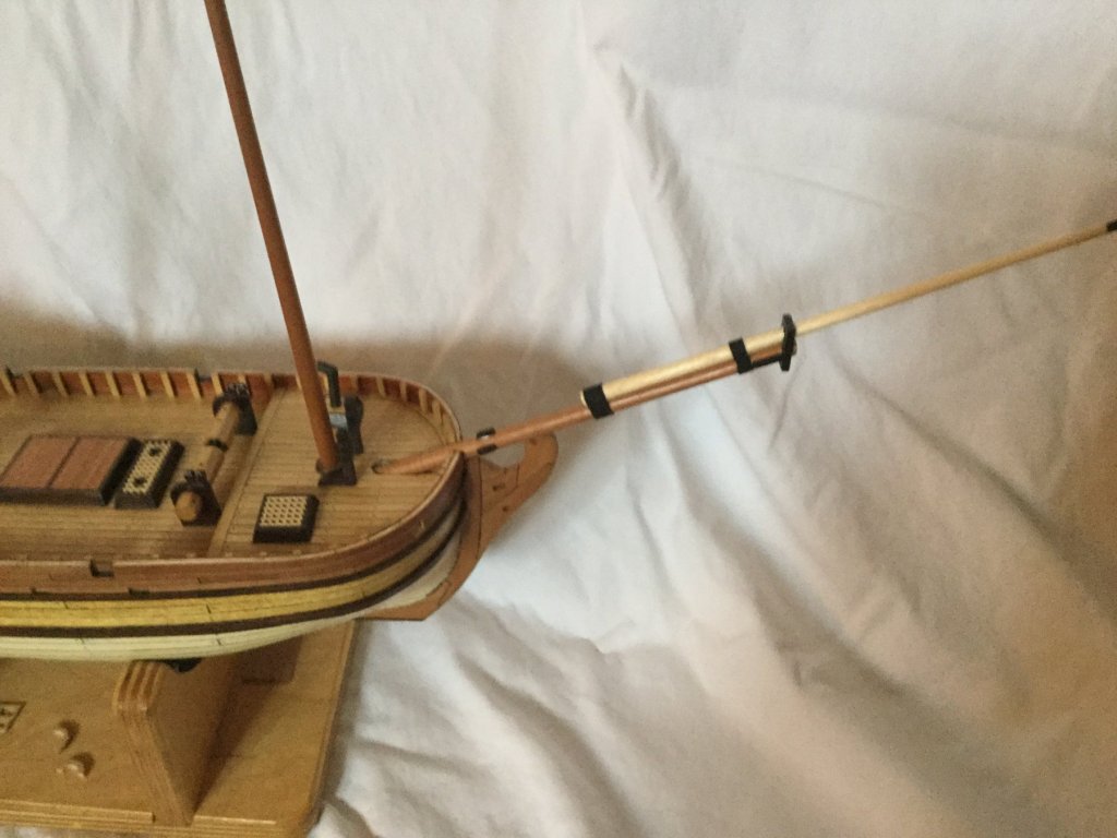
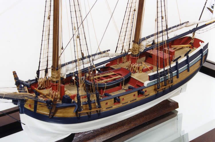
I'm finishing up the masts. The plans call for boom rests on both the main mast as well as the fore mast. This is similar to what was found on "Hannah", "Chaleur" and "Gaspee". "Sultana" and "Halifax" had boom rests on the main mast only, the sails on the fore masts being loose-footed. As you can see from the pictures, Chaluer's fore mast boom rest was quite a way up the mast compared to Independence. The rest is only 3' 8" above the deck on Independence, while the main is 6' above the deck. By contrast, Hannah's fore mast boom rest is 5'6" above deck , according to Hahn's plan. So while it would be okay to have booms on both the main and the fore masts, the boom rest on the fore mast should be raised significantly higher. I'm leaning toward no boom rest on the foremast, with a loose-footed fore sail. What do you all think? Chaleur Hannah


-
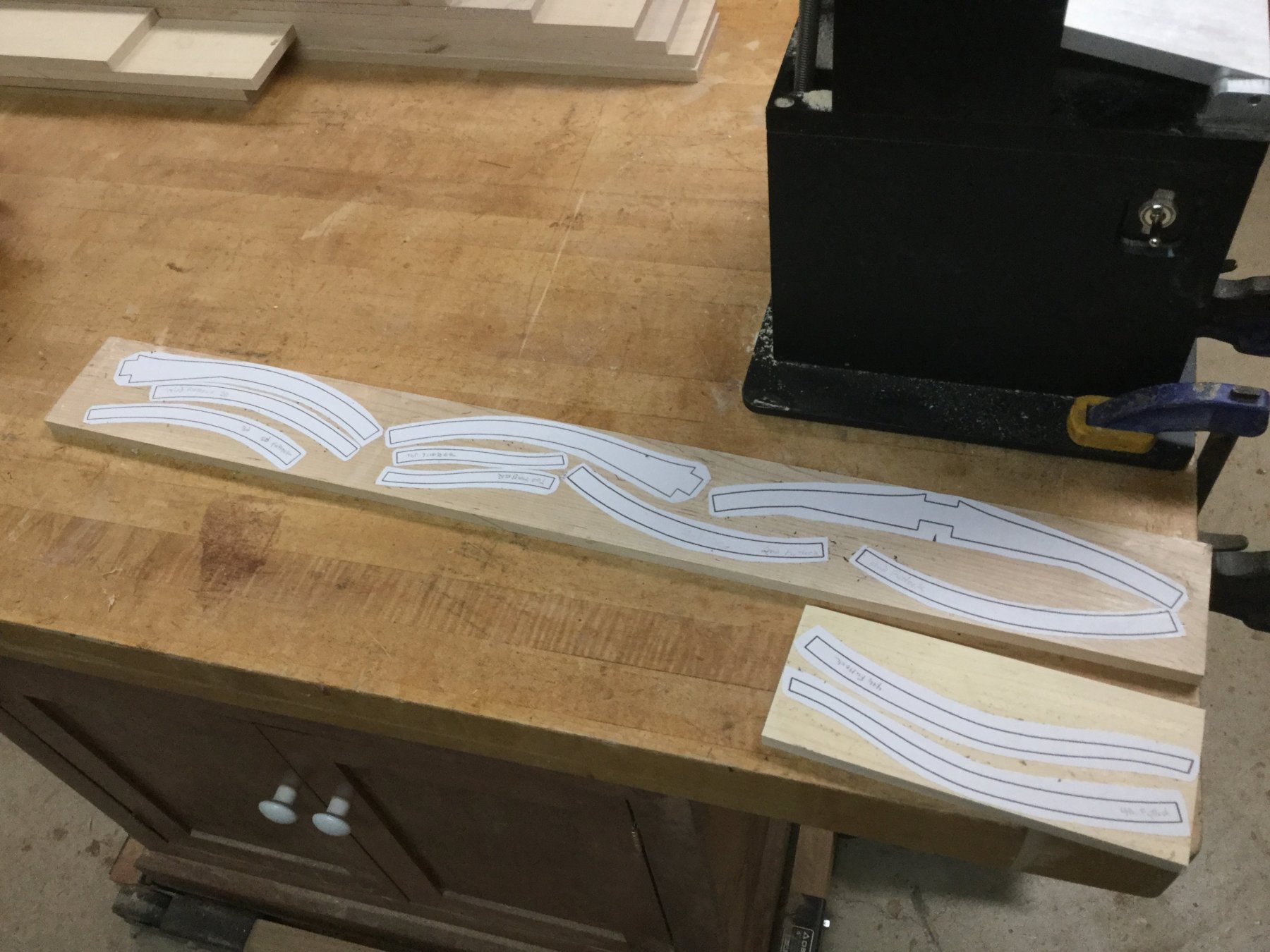
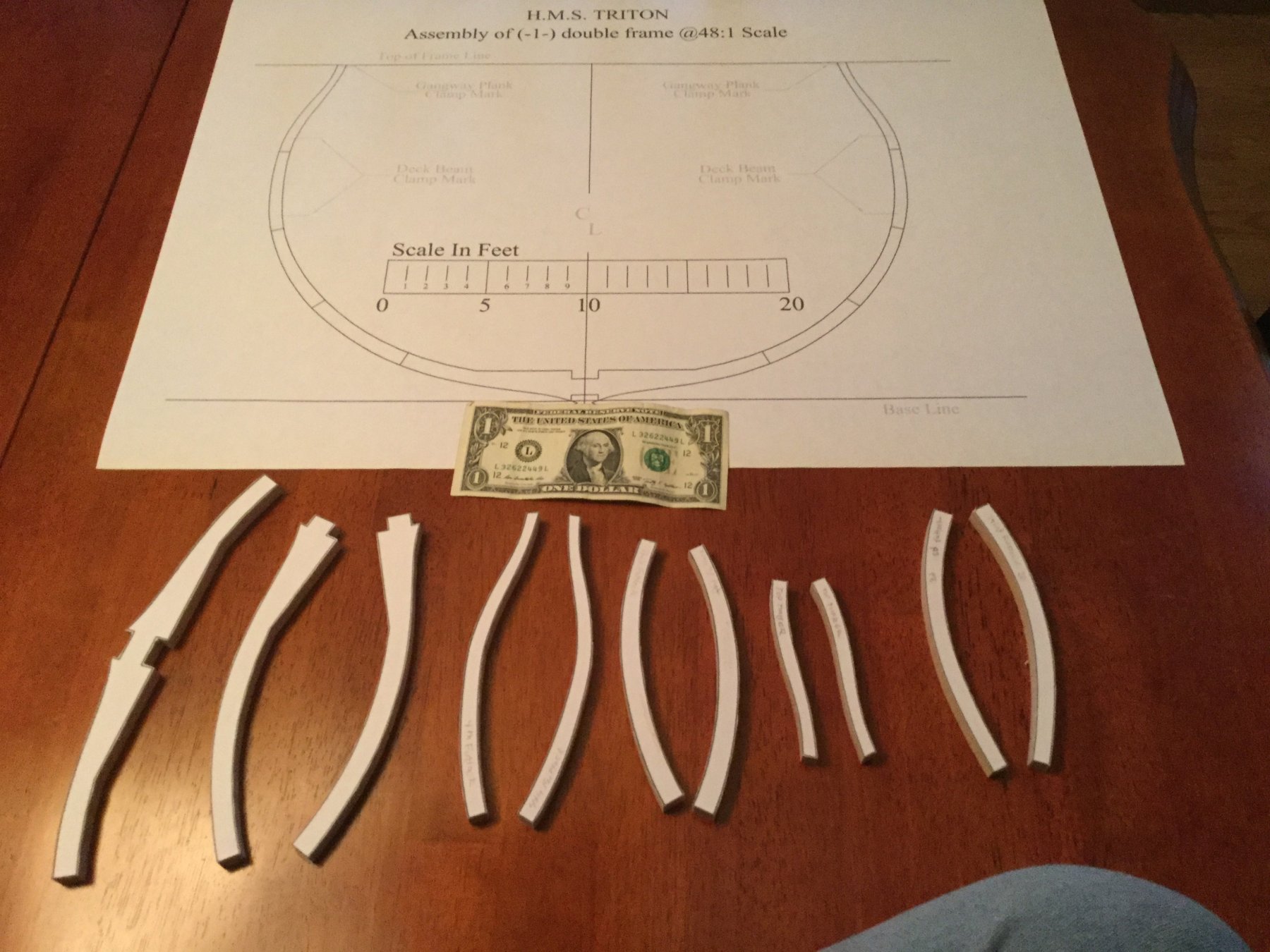
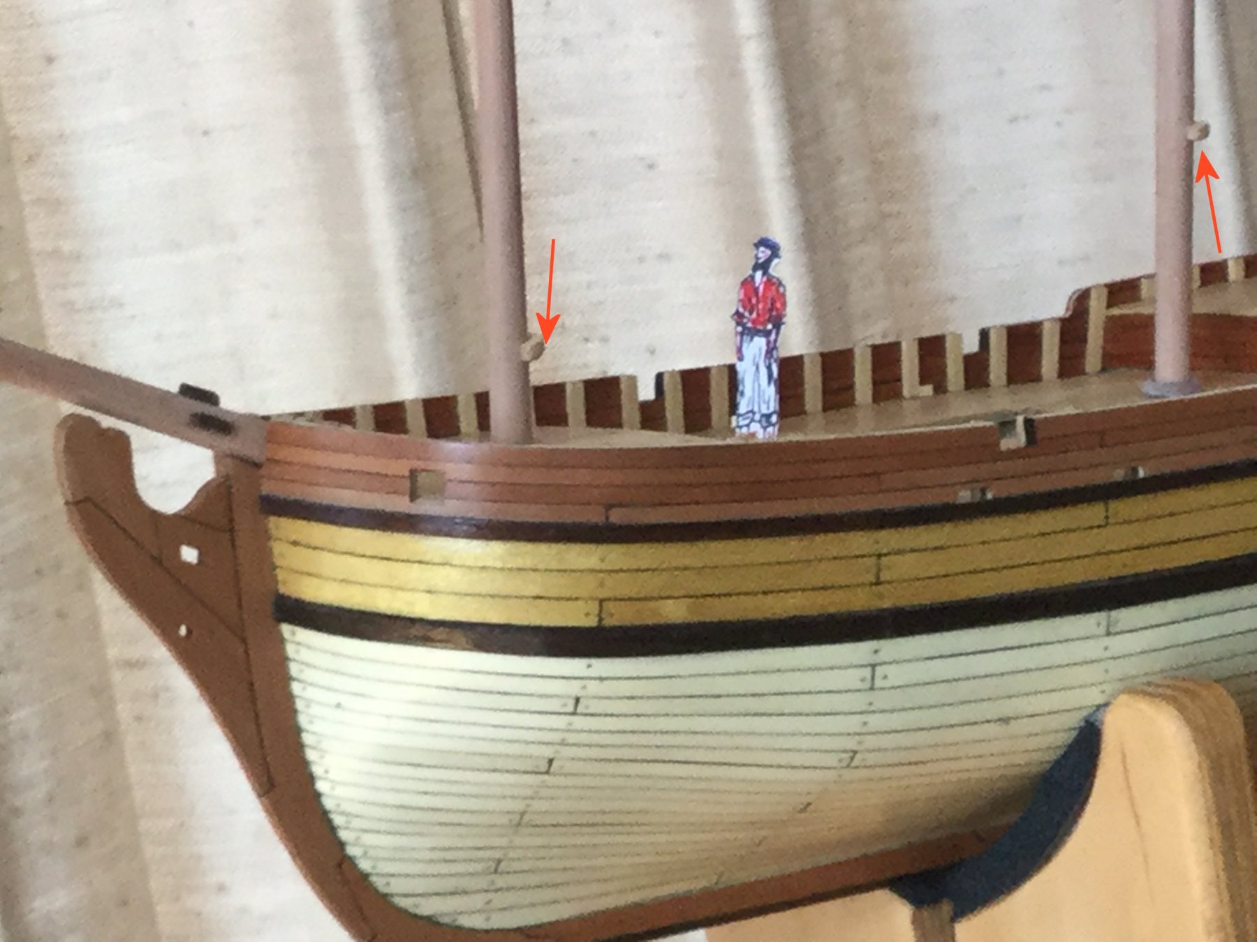
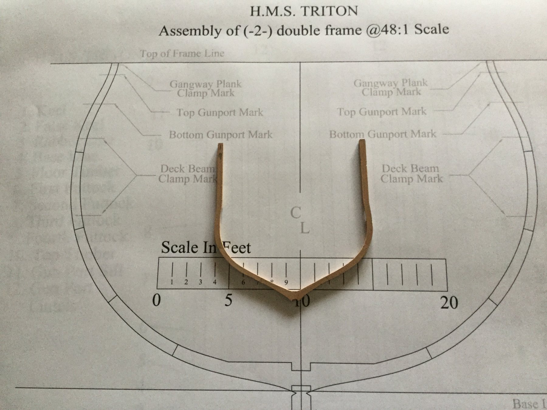
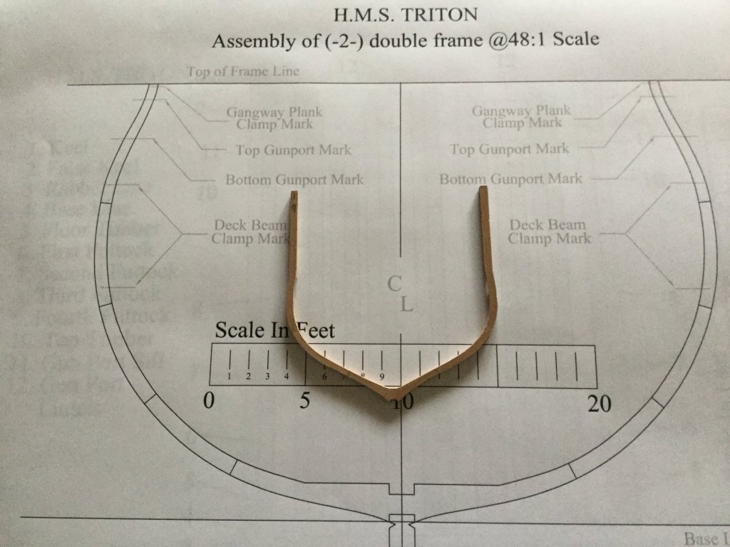
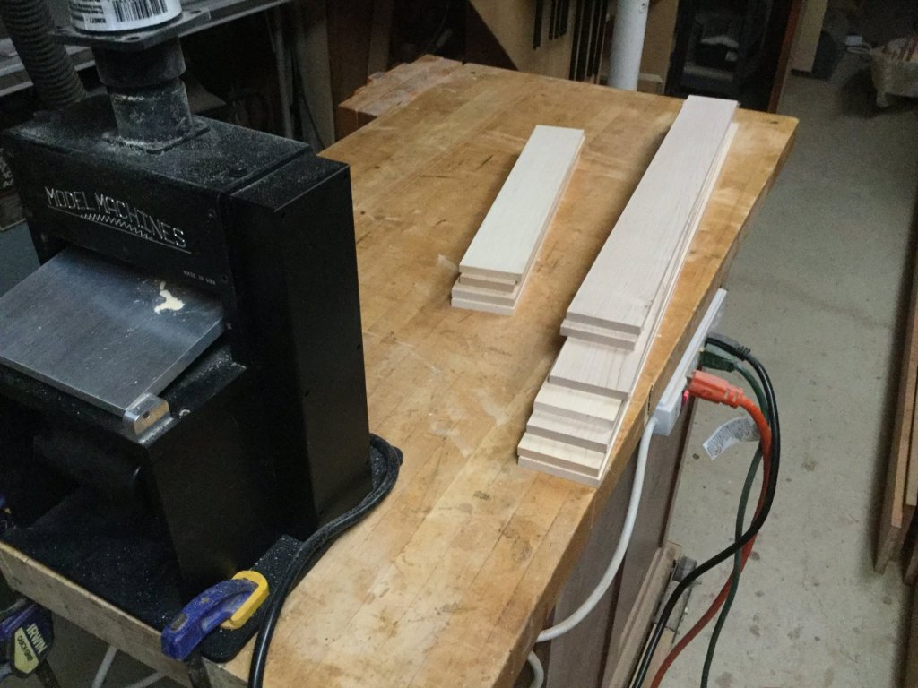
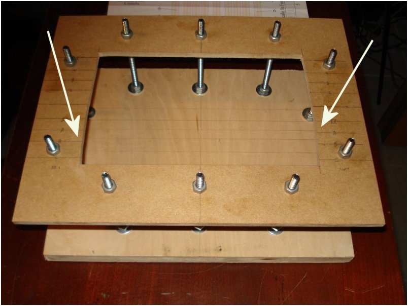
I'm restarting this build. Mike Shanks and I have been planning on doing a joint projet: POF "Hannah" in 1/24 scale...the whole ship. Not sure about rigging yet. I think the Triton cross section will be good practice for that build. I cut out and surfaced the blanks of hard maple I'll use for the frames. The maple is 3/8" thick, giving a final double frame thickness of 3/4". The footprint of the cross section at this scale is huge: 9-7/8" X 14-1/2"! The photo shows the plans for frame 2 compared to a midship's frame of "Fair American" at 1/48 scale. I'm also planning a building jig. The jig in the photo is one of the popular "2 level" jigs used for the cross section, but it takes into account that the plan view profile of the model is not a rectangle. The bulwarks curve slightly. The profile of the sides of the jig (marked by the arrows are clearly curved. Does anyone have a good way to lay out this curve accurately? There is no plan view of the framing in the plans.
-
Started back on this project. I'm currently sanding the inboard surfaces of the frames before gluing them to the keel. There isn't much room to sand inside the model once the frames are glued in place. I own a oscillating spindle sander, but I found the revolving speed was sanding too aggressively. I have a rheostat, but it didn't work on the spindle sander. Fortunately, my full size drill press has an induction motor which allowed the rheostat to control the speed of the revolution. I slowed it down and got a speed where I could control how much stock I was removing more easily. No pictures here...kind of boring work.
-
Beautiful job, Ken! That is a great looking model.
- 481 replies
-
- 2
-
-
- rattlesnake
- model shipways
- (and 1 more)
-
I tend to agree, Don. The ship is "stylized" anyway. Bulwarks are redheart, not vivid red pain, and the planking below the wales is all holly, and it doesn't follow the waterline. The detail at the doublings is some of the most interesting on the ship and I think it tends to get lost with the black dye.
-
C'mon Clare! Post some pictures at least. I need some inspiration!
-
You're right about the historical accuracy of black between the doublings, Russ. Anyone with the opposite opinion?.
-
Thanks, guys! Ken: The sailor is 44mm tall, which is 5'6" in scale height...typical height for a man in the mid to late 18th century. Clare hess chose to stain his masts black between the doublings. I think it looks good and I've added a photo of the result. But I also like the look of pear and maple, without any black stain, as my masts appear now. I've not yet cut the topmasts to length nor made the fids. what do you all think? Black stain or natural wood?