DocBlake
-
Posts
1,811 -
Joined
-
Last visited
Content Type
Profiles
Forums
Gallery
Events
Everything posted by DocBlake
-
 Very ingenious, Jonathan! The cleats look great!
 -
Beautiful work, Don. I'm really enjoying following your progress.
- 653 replies
-
- 5
-

-
- trabakul
- marisstella
- (and 1 more)
-
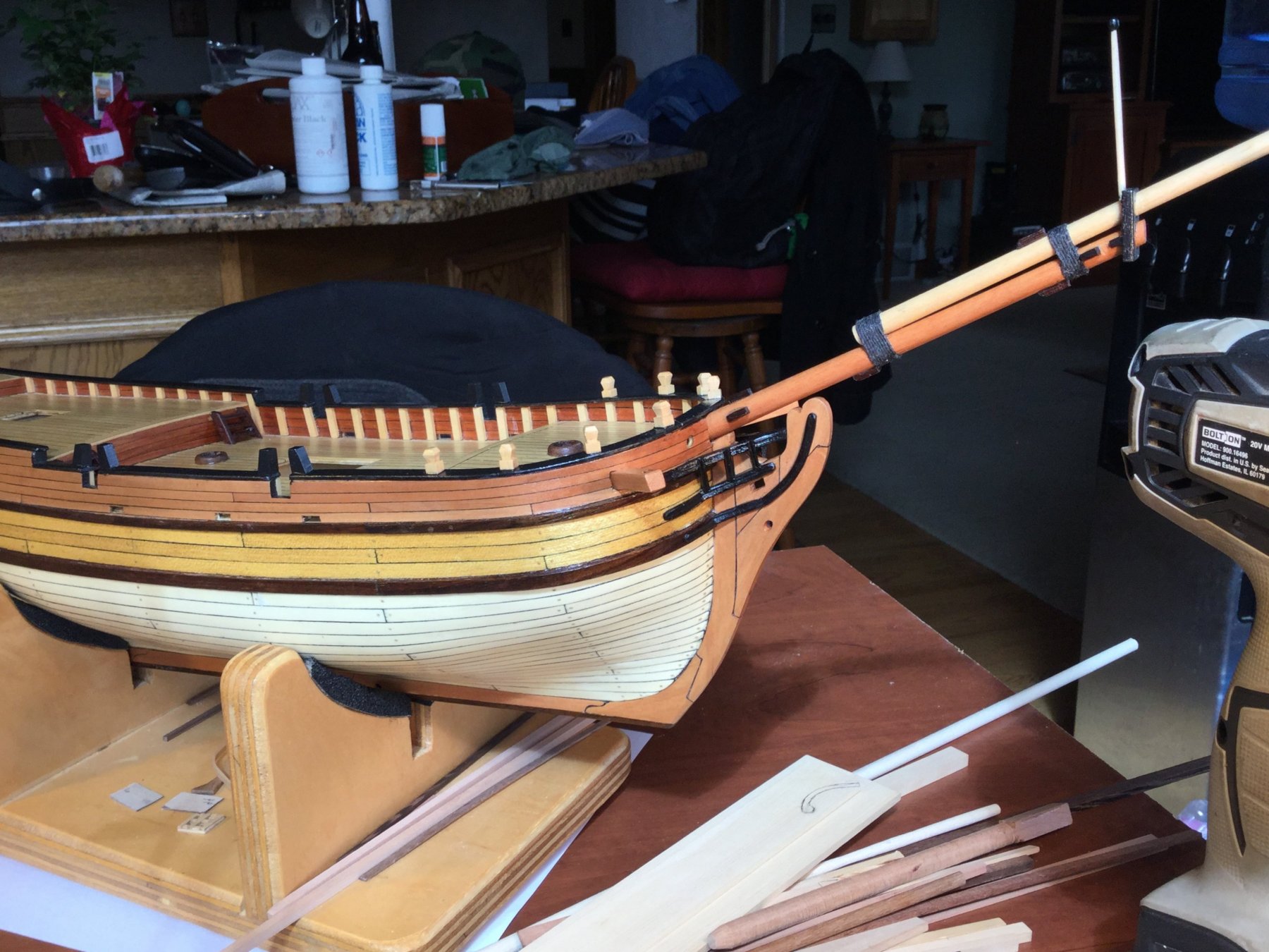
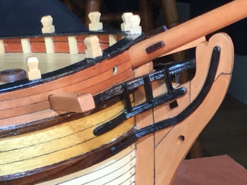
I spent the weekend working on the head rails. Since this is a small, simple vessel, I opted for simple head rails and no figure head. I dyed the rails black and applied a coat of poly. The glare of the light makes the rails look shiny. Much less so in real life. I really sweated the head rails, but I think they turned out OK. I just broke the whole thing down into individual parts and it wasn't as hard as I thought

-
You're making great progress...although those tiny boats look like they are tedious to make!
-
Waiting for more, Don!
-
Looks great, Brian! I really like the job your doing. Are you planning to modify the stern so it's flat/square rather than rounded?
-
Looks good, Brian!
-
I have a few tasks left before moving on to the rigging. The masts, sprit, boom and gaffs are complete. I need to finish the yards. The plans call for the fore mast to have a topsail yard and a crossjack yard, but the main mast has no yards! Both Halifax and Sultana had both yards on both masts and I'm moving in that direction. On the hull I need to complete th quarter deck/poop deck rails, the channels and the swivel gun supports. I also need to add the head rails. I've been avoiding the whole head rail problem, because I can't find an easy solution to constructing them. The kit parts are crap (the scroll work on the stem is metal, again!), so I need to start from scratch. Since this is a fictional vessel I'm not bound by any convention in how I construct the rails. Is anyone aware of a good log or tutorial on constructing head rails from scratch? I can't bring myself to leave them off, because they really do help define these schooners, but I'm having trouble getting my head around how to construct them.
-
Michael: I've used a Dremel cut off wheel to free parts from the billets with good results. With the very small parts you need to go super slowly and cautiously, and always cut with the grain...but you already know that! I can't tell you how many parts for my LSS Armed Virginia Sloop I had to remake because i damaged them removing them from the billets.
-
Great progress! Keep going.
-
Just got my supply. Enough to rig shrouds and stays for the rest of my life!
-
Great stuff, as usual, Don. Excellent craftsmanship. Snow??? We have blue skies and temps in the upper 60's F!! You really are in the Great White North !!
- 653 replies
-
- 7
-
-
- trabakul
- marisstella
- (and 1 more)
-
I picked up a Picket boat on sale at Model Expo. Delivered Friday. I'm making mental notes for when I start. I' do the pear planking also Brian.
-
Michael: That compounding of tiny errors has bitten us all at some point. Hang in there. It's something to learn from and I know that you will recover just fine.
-
Pete: I looked at your build when I was first planning this project and filed away your building technique for future reference. I just reviewed your whole log and I plan to approach the build just as you did. Hopefully my results will be as good as yours!
-
Thanks, Brian. I think I'm going to go with a building board and right angle jig for construction. I cut my false keel way long, and the keel and keelson long, also. I'll glue the false keel to the keel and this will give me plenty of room to screw the false keel into the building board to keep the component in place. When the build is done, the false keel gets cut off, freeing the model from the board. I finished rough sanding the frames inboard and outboard. There should be very little final fairing, and only smoothing to do once the frames are set...assuming the rebates for the keel and keelson are right on each frame! No pictures yet! In looking at the full build Triton plans, I noticed there is a scarph in the keel between frame O and frame B. The scarph is in the vertical plane and I plan to include it in the model. In fixing it's location, I noticed that there is a discrepancy between the full build plans and the cross section plans. In the cross section, the frames are labeled 5, 4, 3, 2, 1, 0, A, B, and C. The identical frames on the full build plans are labeled 4, 3, 2, 1, 0, A, B, C, and D. Does anyone know why the discrepancy?
-
This model is being built in 1/24 scale: a scale that introduces a lot of problems in terms of scaling. For example, the layout lines for the parts and the profile views etc. are about 1/32" thick, leading to a lot of potential error especially in terms of room and space layout of the frames on the keel. What I'm wondering is if anyone can help me out with some pointers on building the jig to construct the model. How do I size the upper portion, with the cutouts for the frames, given that the frames are curved? How do I account for the slight curvature of the frames moving aft in the plan view? How do I keep consistent space bewtween fromes, given the thickness of the layout lines? I'm almost thinking of not using the 2 tiered jig as many have employed. Instead, after screwing the keel/false keel assembly to the building board, I'd set the first frame on the keel, use a standard precut spacer for the space between it and the second frame, then set the second frame. Using the standard spacer again, I'd set the third frame and so on. I would need to make a right angle jig to keep the frames square to the keel and their tops level, but I could avoid the upper tier of the jig. What do you think? Any advice or tips? Thanks so much for any help you all can lend!
-
Tony: I'd like to PM you, but I get a message saying you can't receive messages. Can you post your email address or check my profile page for some questions I have? Thanks!
- 132 replies
-
- 2
-
-
- triton cross-section
- cross-section
- (and 1 more)
-
Hi Tony!
As you may know, I'm starting the Triton cross section in 1/24 scale: a scale that introduces a lot of problems in terms of scaling. For example, the layout lines for the parts and the profile views etc. are about 1/32" thick, leading to a lot of potential error especially in terms of room and space layout of the frames on the keel. What I'm hoping for is that you can help me out with some pointers in building the jig to construct the model. How do I size the upper portion, with the cutouts for the frames, given that the frames are curved? How do I account for the slight curvature of the frames moving aft in the plan view? How do I keep consistent space bewtween fromes, given the thickness of the layout lines?
I'm almost thinking of not using the 2 tiered jig you and others have employed. Instead I'd set the first frame on the keel, use a standard precut spacer for the space between it and the second frame, then set the second frame. Using the standard spacer again, I'd set the third frame and so on. I would need to make a right angle jig to keep the frames square to the keel and their tops level, but I could avoid the upper tier of the jig. What do you think? Any advice or tips? Thanks so much for any help you can lend!
PS: Thanks for your superb build log and model. I really enjoyed it.
-

I don't know why you can't access me through PM, unless the box is full or something. I'll have to figure it out.
Building the jig was easy, I just set the height for the widest part of the cross-section -- i.e. the widest frame at it's widest height. I then measured the widths of all the frames at that height and printed the plan with all the frame markings. I put this on a sheet of plywood and cut out the part that would hold the frame. I then aligned that very carefully with the frame layout on the base, as you should see from my log, and drilled holes for the bolts through both pieces whilst still aligned. I then set the height for the cutout by placing the holding nuts at the right height.
For consistent spacing, as you might seen from my log, my cutout was such that it had indents for each frame, so the indents acted as spacers. In terms of measurement, it's a question of consistency as to where you take the measurements from. In general I think the safest is to use the outside of the line, but that varies with the situation. Sometimes I use the middle -- e.g. between planks.
The other method you propose of having a movable jig with set squares is possibly the more common method, and is one that is also used when making longer models of the full ship. It looks good to me, but for my particular purpose with the cross-section, I thought the jig method would be simplest.
I'm always happy to help, so don't worry about pestering me!
Tony -
-
-
-
I missed that this is a retrospective log, but that's OK. At least we're assured the result is successful!
- 53 replies
-
- 3
-
-
- clipper
- restoration
- (and 1 more)
-
Huge task, but you seem to be making progress. This will be interesting to follow. Best of luck!
- 53 replies
-
- 3
-
-
- clipper
- restoration
- (and 1 more)
-
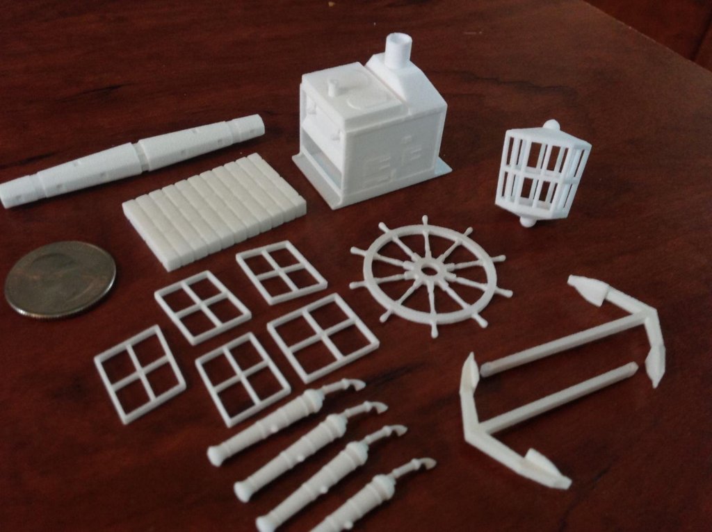
3D-printing for modellers?
DocBlake replied to Jean-Pierre's topic in Modeling tools and Workshop Equipment
3-D parts are already being produced. My AVS "Patrick Henry" had parts included. I didn't use them for a variety of reasons, but they were actually quite nice. Here's a photo. Parts are available at shapeways.com. Search for "model ship parts".