DocBlake
-
Posts
1,811 -
Joined
-
Last visited
Content Type
Profiles
Forums
Gallery
Events
Posts posted by DocBlake
-
-
Jeff: Are you sure the cannon is in proper scale? Many kits have parts that are grossly wrong scale-wise. The practicum suggests adding another bulwark plank, which you can do. But realize it will change the sheer profile and other relationships on the ship. If the gun is out of scale, replacing the cannons may be the better option. If you plan to add another plank, lay out the gun port locations (the plans should help you locate these in relationship to another part of the model; ( 6 mm aft of the aft edge of bulkhead #6 as an example). Lay out the framing and the new stanchions for the gun ports. Then add a stanchion next to each bulkhead between the ports and all the way to the bow and the stern, so the plank has support between each port also. Hope this helps
-
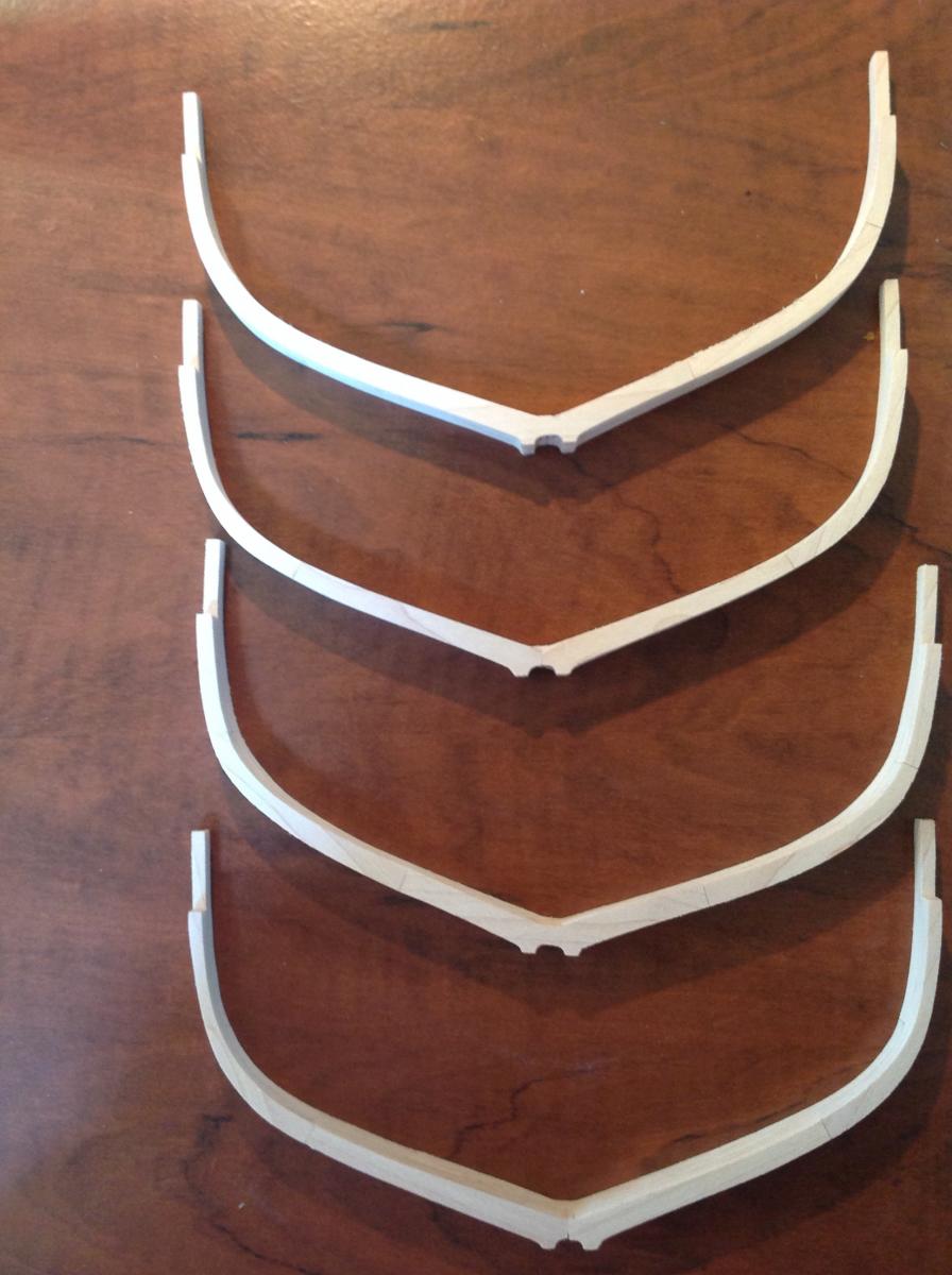
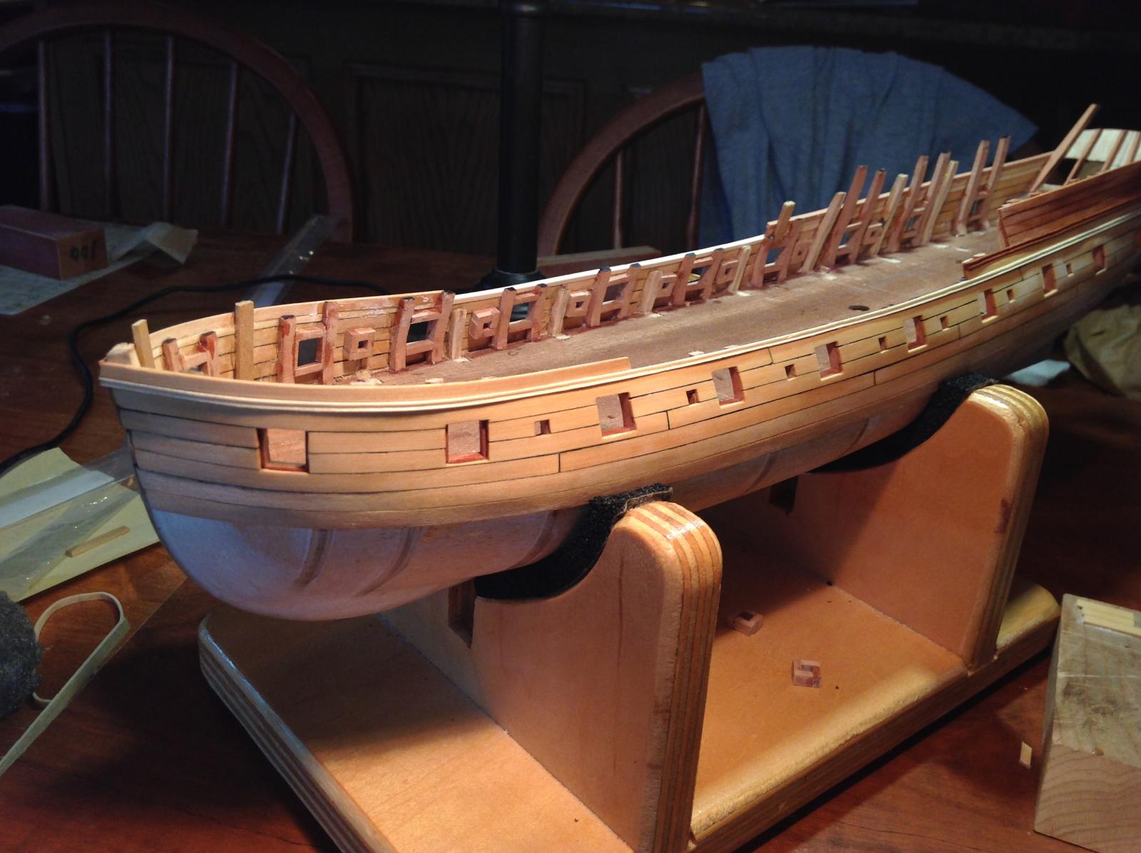
I've started gluing up the frames. Frame 0 is amidships. The frame's number increases going forward from there. Frame A is just aft of Frame 0, and the frames proceed alphabetically moving aft from there. Frames 0, 1 2 and 3 are straightforward and require no beveling. The numbered frames forward of these (#4-11) require progressively more beveling as the bow is approached. The same is true for the lettered frames moving aft. The first couple after Frame 0, Frame A and Frame B, require little or no beveling. The remainder (C through Q) are beveled. I finished and glued up the first 4 frames, 0 through 3. I'll also begin gluing up the other frames, as well as constructing the building jig and keel. My frames are maple. The deadwood, rising wood, keel, stem and stern post are all cherry. I'll add a rosewood or ebony false keel. I will also blacken the joints of all the deadwood parts to simulate caulking. I think the contrast in woods will be nice!

-
-
Great progress, Jeff. Good job on the planking and finishing,
-
-
Thanks, Dan.
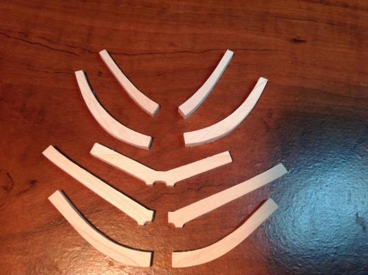
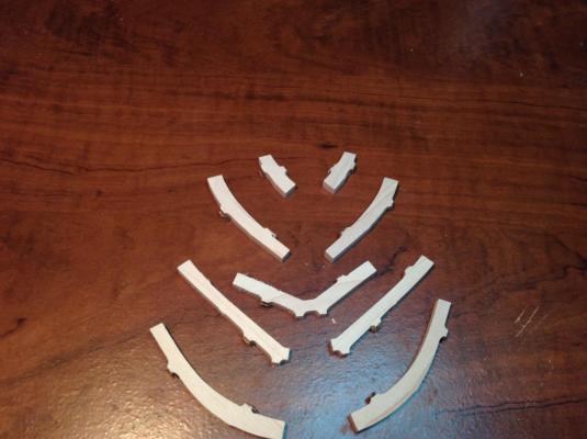
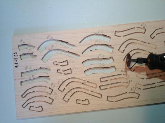
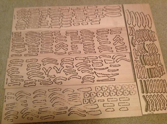
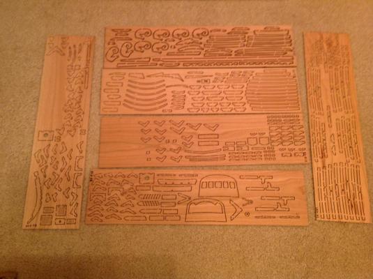
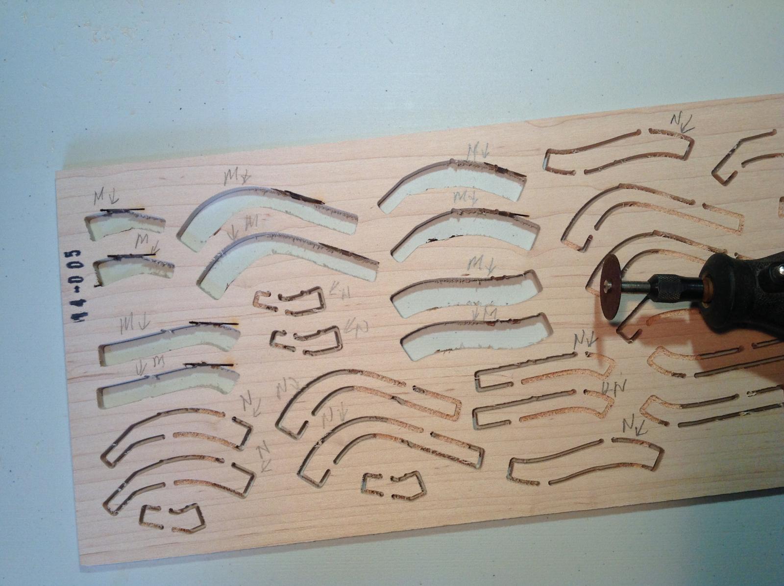
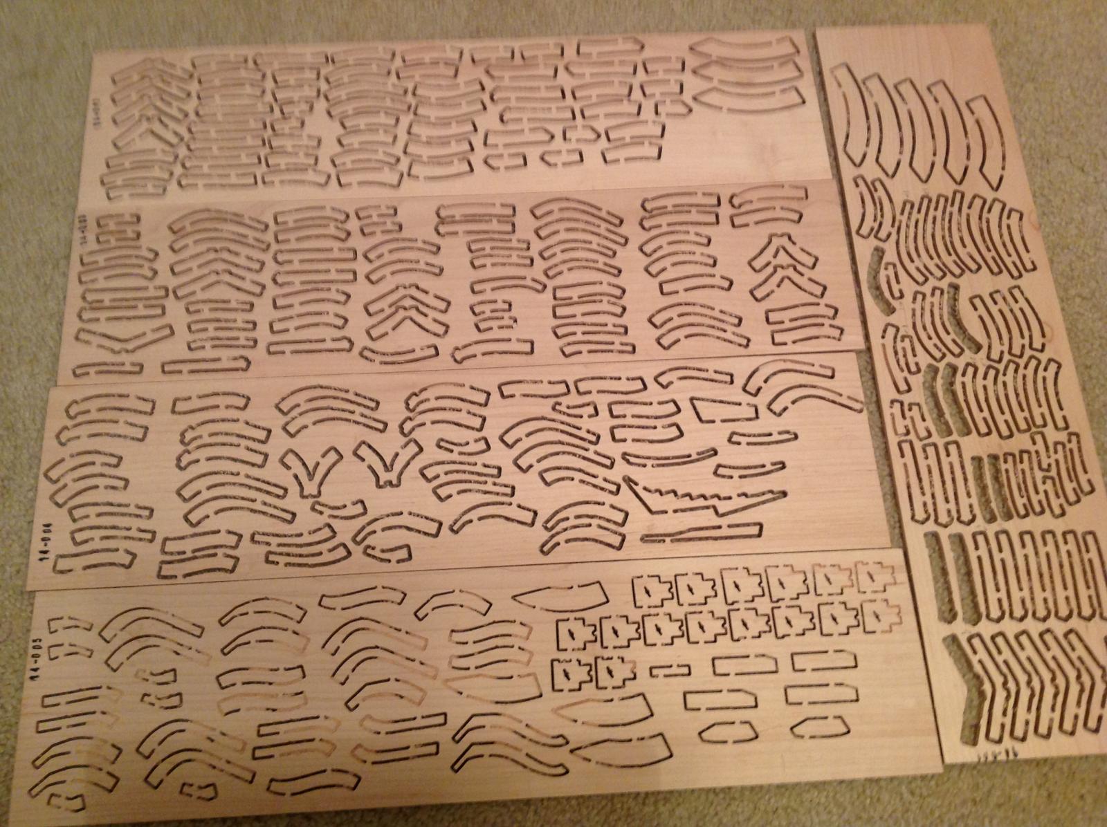
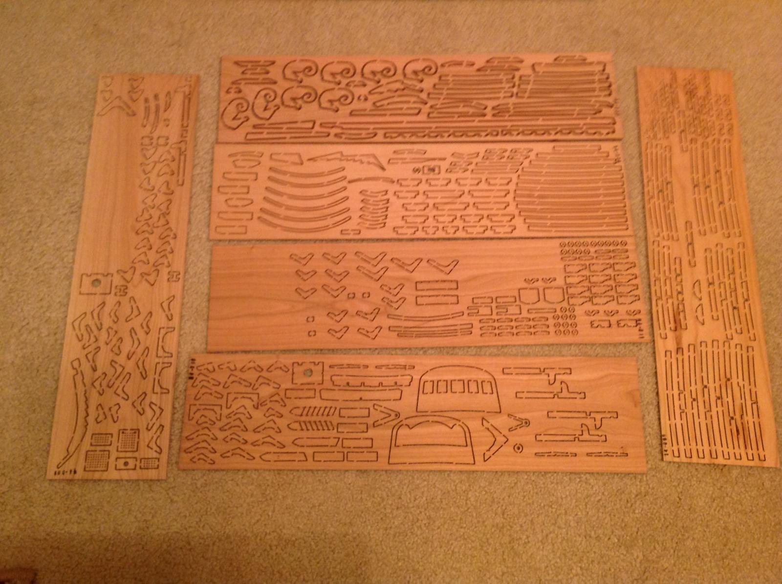
The first step in the build is to make the frames. They come attached to the hardwood billets by two tabs. I found the easiest was to remove them from the billet was to use a Dremel tool and a cutoff wheel. In the photo, if you look carefully, you can see the burned area on the billet where the parts had been attached. Each frame is made up of 9 or 10 parts. The tabs are then cut off of each part, and the parts lightly sanded. The first layer of parts is stuck to a template of the frame with double sided tape, and the second overlapping "sistered" layer of parts is glued to the first. The photo gives an idea of scale
- mrshanks, SkerryAmp, Cap'n Rat Fink and 3 others
-
 6
6
-
Is it reasonable to blacken the joints between timbers making up the deadwood as one would do with deck planks? It's done on built up stems and keels, so why wouldn't the deadwood be caulked?
-
Hi Keith!
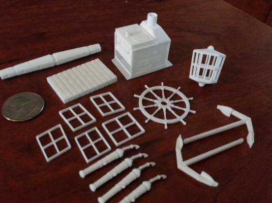
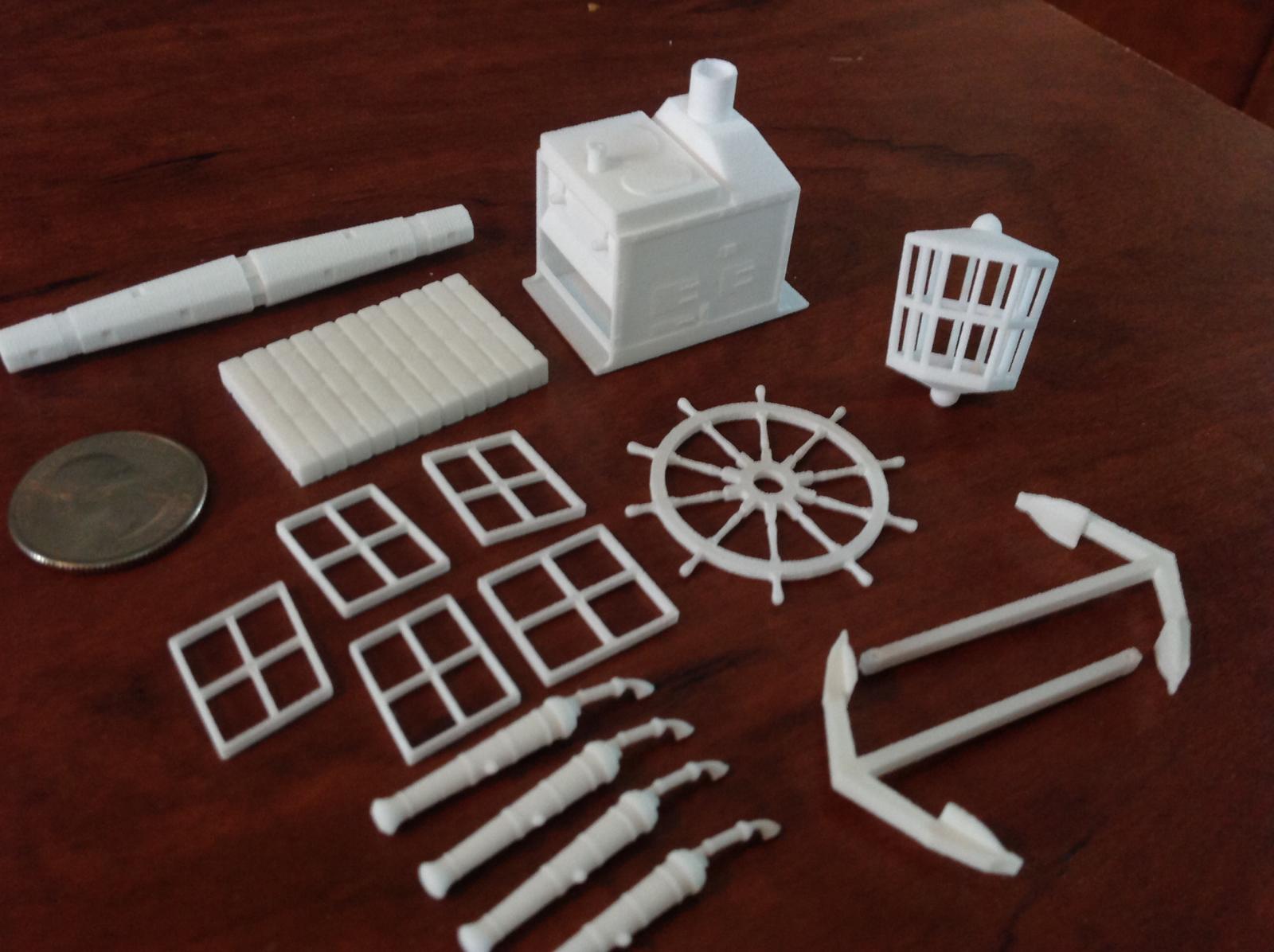
Bob's AVS is not technically out of production, but he won't manufacture a kit unless he has a lot of 8 orders and business has been slow. He doesn't really advertise. If you are interested, I believe he has one AVS in stock right now. As to this Kit: It's quite a bit different from the MS AVS. The kit differs from Bob's previous kits in that the frames are beveled before installation, making the fairing of the hull, both inside and out, muck easier. The 3D parts are quite excellent. The detail is amazing. You'll have a hard time looking at typical MS, Amati, Corel Britannia metal castings and then using them. Photo below of the 3-D printed parts.
PS: If you're interested in selling "Halifax", I'll take it off your hands!

- mrshanks, Jaxboat, aviaamator and 7 others
-
10
-
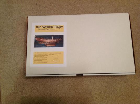
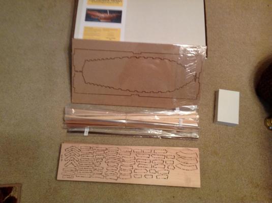
I'm beginning my build log of the Lauck Street Shipyards POF kit of an Armed Virginia Sloop, an admiralty style kit in 1/32 scale. The kit arrived in it's box and it is heavy! The contents are high quality hardwoods (primarily cherry for deck beams, knees, carlings etc. and hard maple for the frames) with lots of strip wood of various species for planking, trim etc. There are also a large number of 3-D printed parts; this being the first kit to offer them. There are 5 sheets of plans, each 36" X 24" included. I may alter the kit, and add additional details and possibly substitute some different woods, but I'm basically going to build it out of the box. Comments, criticisms and suggestions are welcome!
Here is the box, and some shots of the maple and cherry billets containing many of the parts.
-
-
Jonathan: I think that the fixes and modifications that creep into each of these builds is part of the allure. You're right, of course. Everything will need to be checked and double-checked, especially at the stern end. I know that the deck clamps have already become an issue, and the rudder post may be also. But fixing these things is part of the game, right? It does cause heartburn, though. And in the end, people won't know the difference. But as you and I have said many times in build logs : "I will!".
-
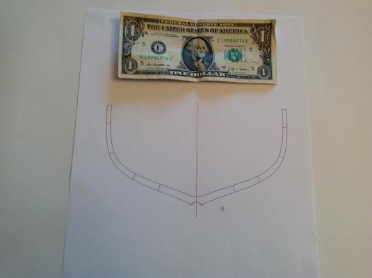
Thanks for the comments, guys. Jonathan: I did compensate for the foreshortened view on the Hahn plans. My problem is that I got the angle of the transom in reference to the counter wrong. The transom should lead even further aft (from the vertical). The result, had I done it, would have been a "shorter" transom with more of the quarterdeck bulwark planking above the level of the transom. If I measure the Hahn plans, the distance from Frame #28 (Mamoli bulkhead 8) to the aftermost point on the transom is 6-5/8". This is the length of the top quarterdeck bulwark plank. On my model that distance is 6-5/16". 5/16" too short! The only solution now (other than starting over!) is to cut down the height of the transom as I indicate in the drawing. I'll have to make some adjustments also when I fit the quarterdeck deck clamps.
-
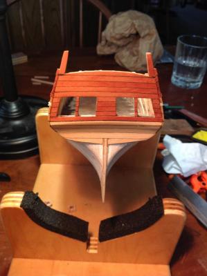
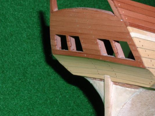
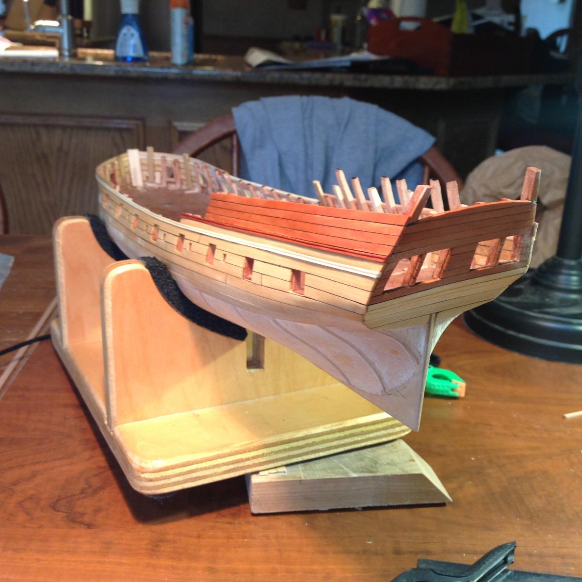
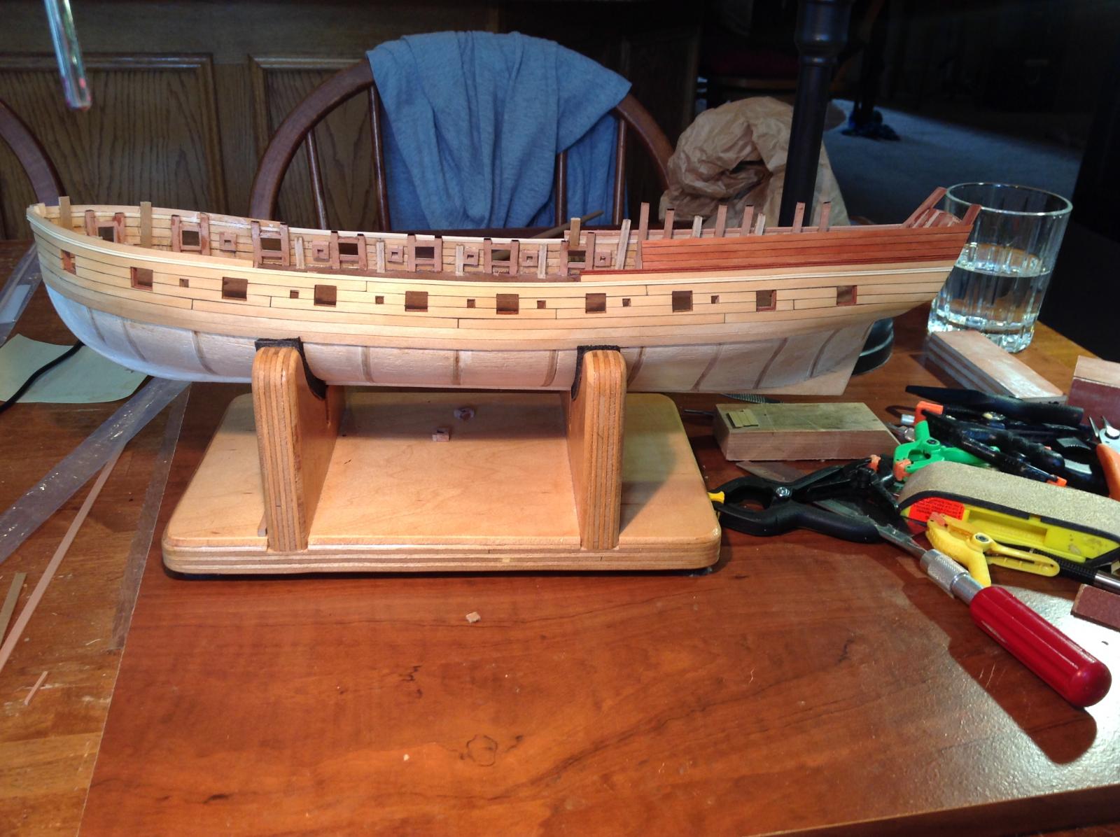
I ran into another big problem, and it's the damn transom again! That structure has caused more grief than the rest of the build combined. When I completed the planking above the wales, I realized that my planking did not extend up high enough over the completed transom planking. The space would have been fitted with stanchions and a rail. I thought I had the angle of the transom to the counter correct when I glued it in place, but I was off a bit. The transom should have been angled a little more from the vertical than I left it. The result was that the planking of the quarterdeck bulwark is too "low" relative to the transom. No room for a rail! I've enclosed a photo of my transom and quarterdeck bulwark planking as well as one from Bob Hunt's practicum. You can easily see how much "taller" the quarterdeck bulwark planking is on Bob's model. I'm open to suggestions, but I think the only solution is to cut down the transom planking a bit like the photo with the blue line suggests. This will have to be carefully measured and drawn out to accommodate the stern carvings to come later. Any other solutions?

-
Try the stealer(s) near the keel, right next to the garboard strake.
-
Jeff: I helps to be retired, which I have been for 6 months. I run a consulting business from home, so when I go to the "office" I'm still really near the shipyard!
-
-
-
I'm currently starting a Lauck Street true POF kit build of an Armed Virginia Sloop of 1768, I'd like to include the stove, but the Brodie stove didn't begin to be used until about 1781. Does anyone have a link to photos or plans of ship's stoves predating the Brodie? If not, I'll go with the Brodie, accuracy be damned! Thanks for the links, BTW.
-
-
-
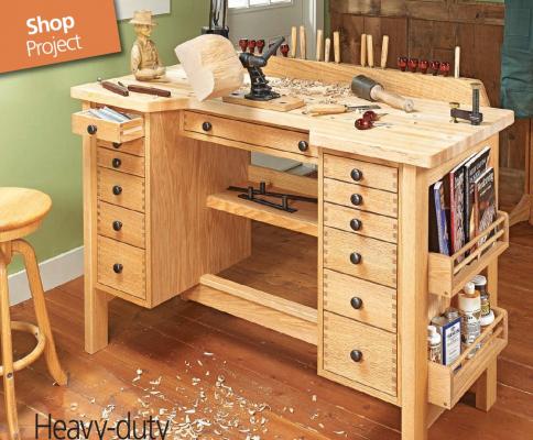
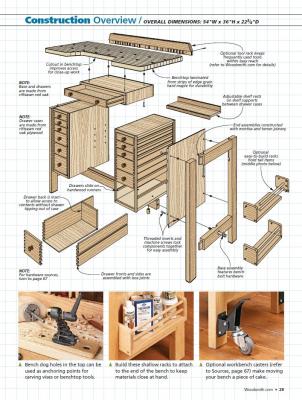
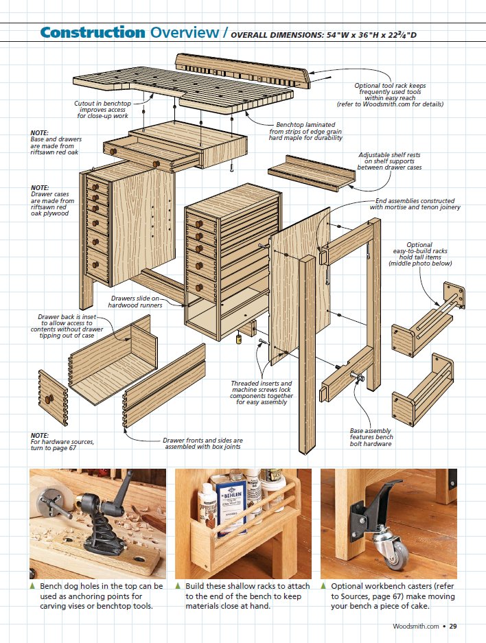
The workbench is in the current Woodsmith #219 June/July 2015. The slant-front cart is a free download. Try this link: http://www.woodsmithshop.com/download/411/slant-front-tool-cart.pdf
If it doesn't work, google slant-front cart and go to the Woodsmith website. All you need to do is subscribe to free email tips by entering your email address and you can download the plans.
-
Nice job! A SketchUp model would be very cool to have.
I'm building a storage cart for parts from Woodsmith plans. This is to help organize the clutter around my work area. What I'd like to do after that is build the hobby bench featured in the current edition of Woodsmith Magazine, Here are some photos of the storage cabinet and the workbench

-
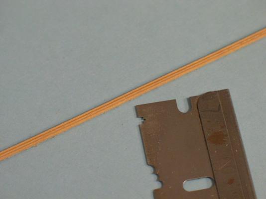
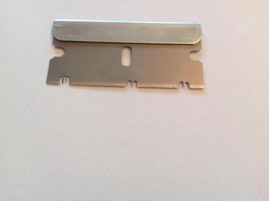
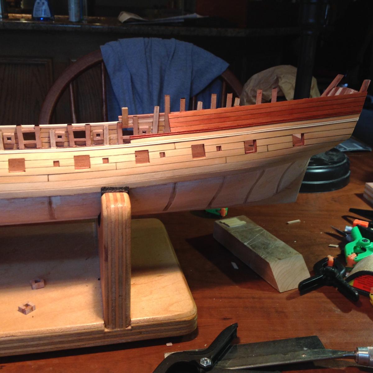
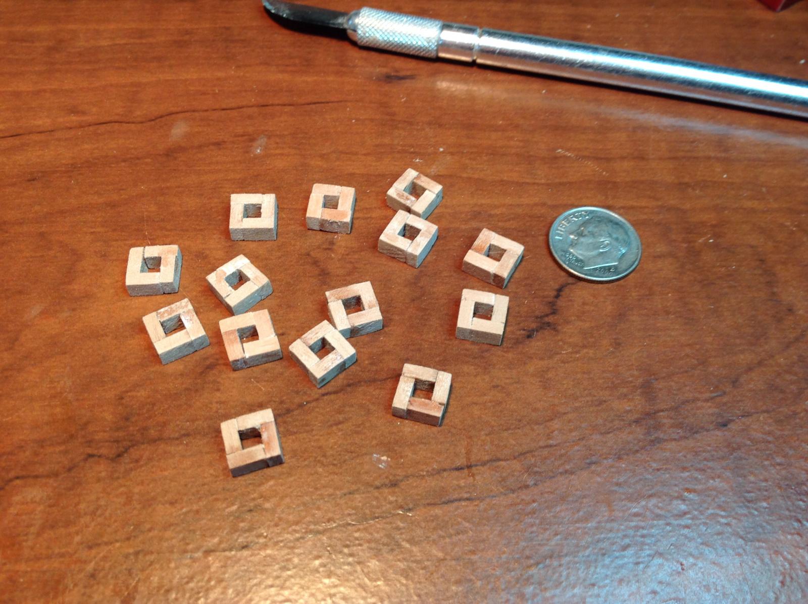
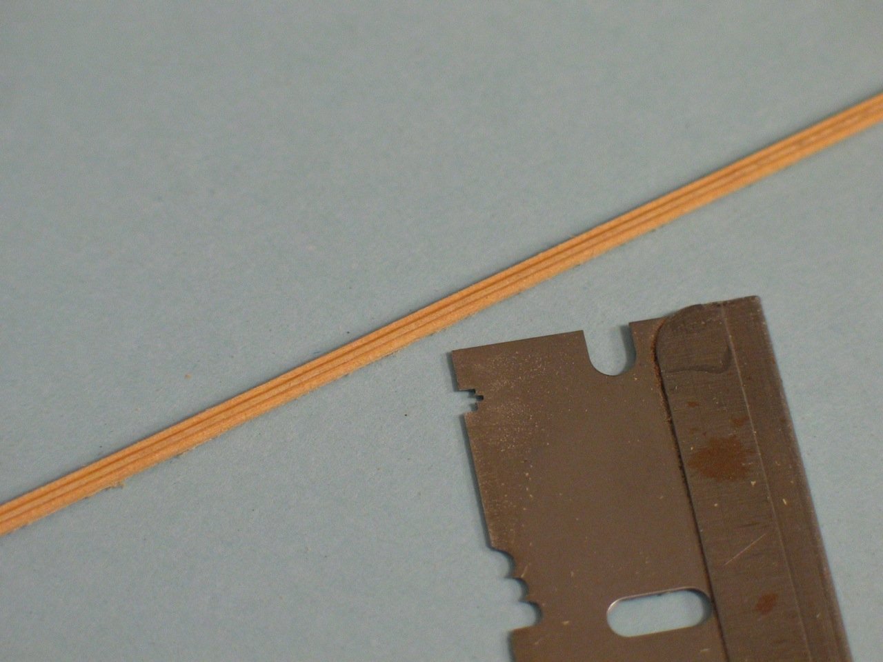
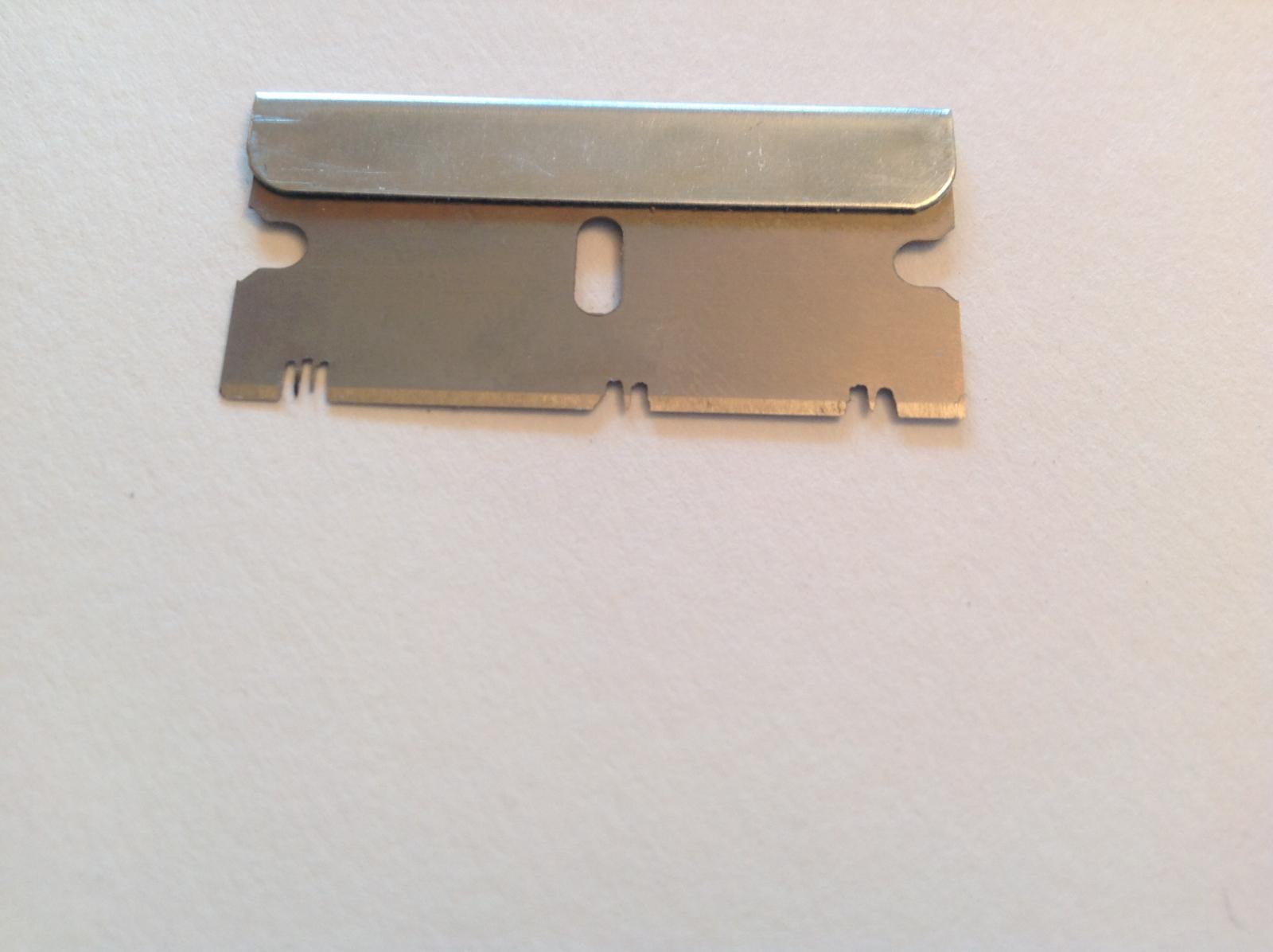
After cutting the sweep ports I turned my attention to the main rail and swiss pear molding (for the quarterdeck bulwarks). The practicum calls for a molding cut with a razor blade into which is ground the 3 bead profile. This is then used like a molding plane to "scratch" the profile into the wood. I tried a dozen times to get the 3 bead configuration right, and failed each time. The problem is the the molding strips are .075" X .075", pretty small! So I copped out and did the easy thing: I cut the molding to have 2 beads, not 3. In the end, no one will notice! (except me!). The photos show the practicum molding and the blade used to cut it as well as the blade I used to produce the 2 beaded molding. On my razor blade is a profile for the 3 bead molding that didn't cut well at all. I used the profile to the extreme right. Shown are two moldings: one in swiss pear, the other in holly.

-
Beautiful build. It makes me want to start mine...but I need to get a little more experience before attempting this POF scratch build. I purchased the Lauck Street Shipyard's POF kit "Armed Virginia Sloop" and will soon start a build log. Hopefully this will boost my experience level and make the Granado cross section doable! BTW: If you've not seen the Lauck Street kit, it is awesome! The 3/8" scale makes a fairly large admiralty model. The build style is similar to Harold Hahn's, with sistered frames. I ordered mine with hard maple frames and cherry keel and deck framing for contrast. A beautiful kit.


Armed Virginia Sloop Patrick Henry by DocBlake - FINISHED - Lauck Street Shipyard - Scale = 1/32 - POF Admiralty Style
in - Kit build logs for subjects built from 1751 - 1800
Posted · Edited by DocBlake
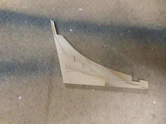
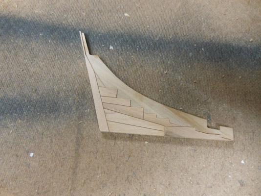
I am playing around with the deadwood assembly for the keel. The deadwood is made up of 4 parts glued together. I plan to blacken the joints between all the parts to simulate caulking, but I also think that some of the component parts of the deadwood can be broken down further than in the kit. For instance, parts SD1 and SD2 were probably each made up of smaller parts on a real ship. I'll simulate this by scoring lines in the parts and darkening the scoring with a pencil to simulate caulking between the parts. Here's a shot from the practicum showing the deadwood, and my proposal to alter it's appearance . What do you think?