


Snug Harbor Johnny
-
Posts
1,379 -
Joined
-
Last visited
Content Type
Profiles
Forums
Gallery
Events
Posts posted by Snug Harbor Johnny
-
-
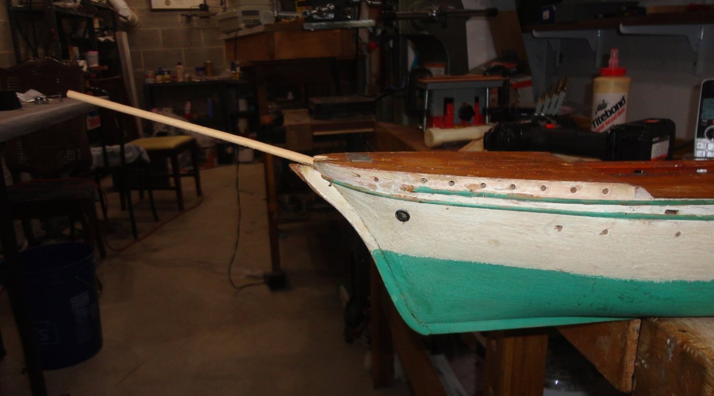
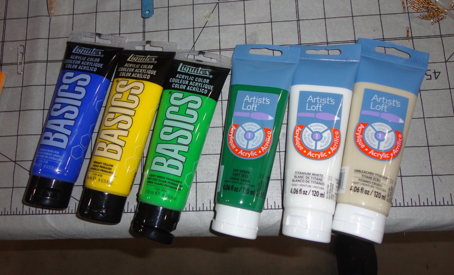
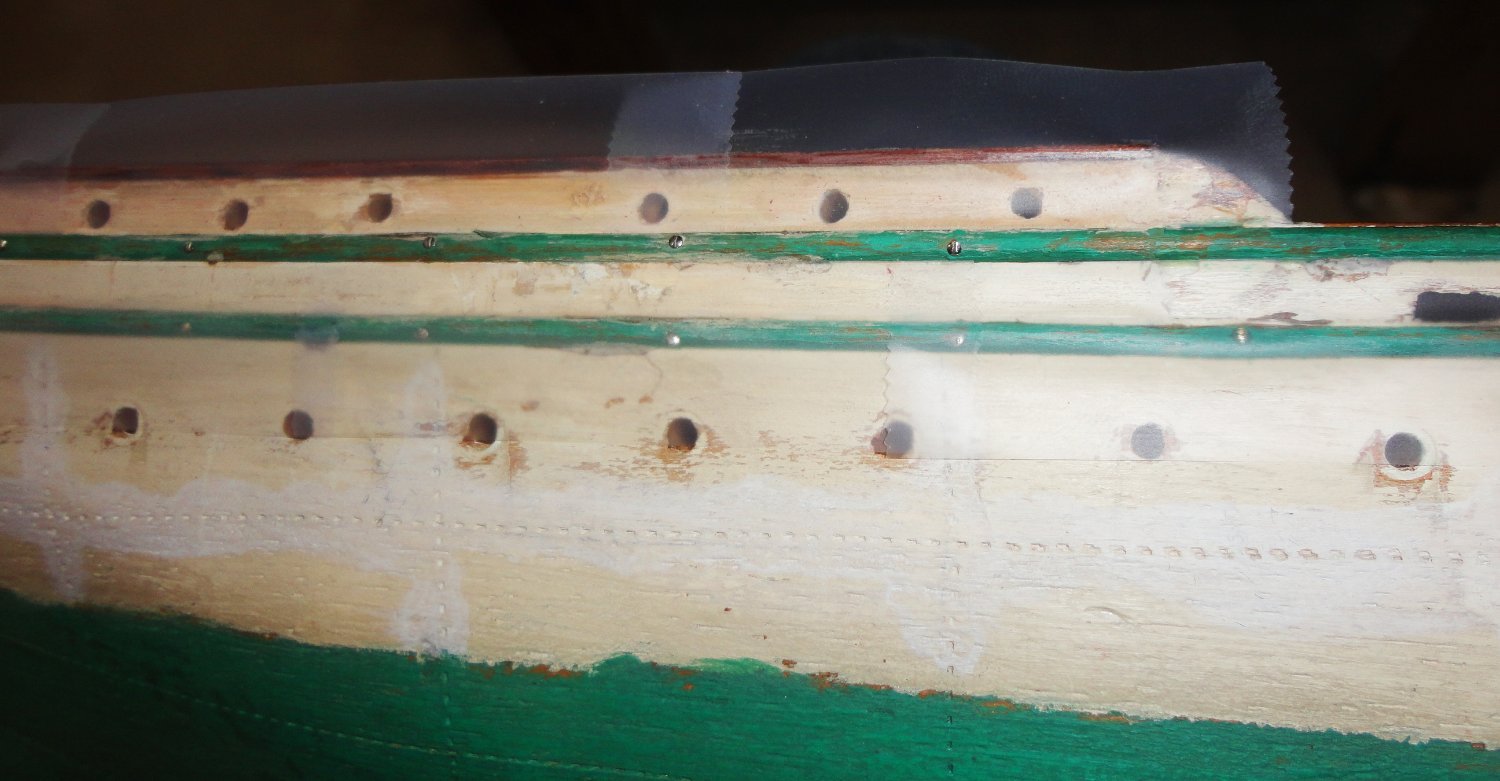
Now it's time to paint the hull. I bought a few tubes of middle grade acrylic colors at a local craft store ... I suspect that this is about the same as in the little bottles for models, but 5 bucks for a big fat tube seems like a better bargain. The finish is flat, but with multiple coats can be semi-gloss - but I'll stick with flat.

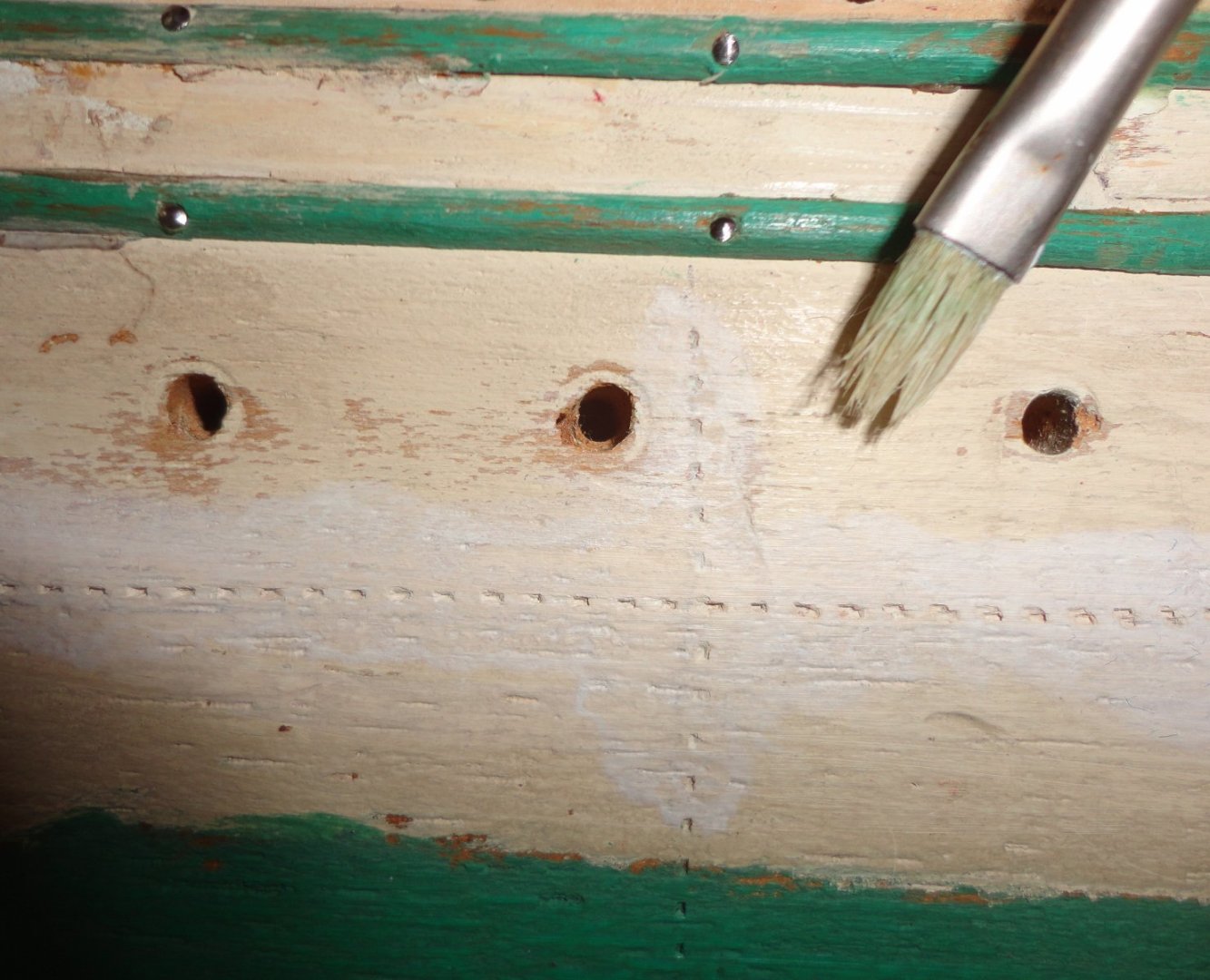
I didn't want 'dead' white, so mixed a little unbleached titanium with mostly white. Thinning a little with water (no smells with acrylic), the barely ff-white white was 'pounced' into the divots made earlier to make sure paint got in there - which would have otherwise been dark dots. The brush used was a relatively still artists' detail brush. Note that the original waterline in this close shot is definitely a bit 'rough'. I'll do a little better but NOT try for a 'dead straight' fine line ...
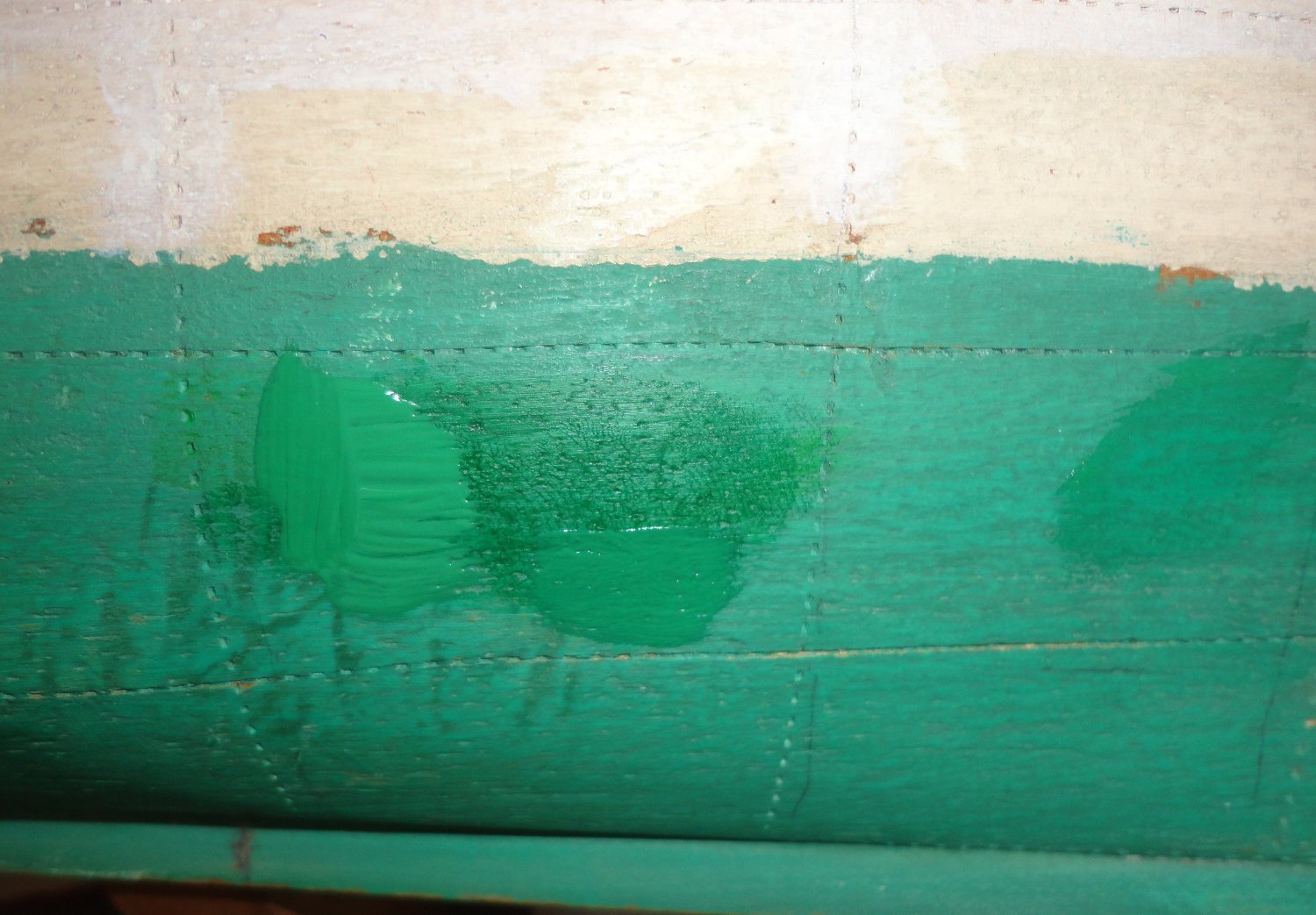
This project is a restoration, so I wanted to hand paint as the builder did - leaving some grain visible on close inspection, as opposed to trying to fill everything to a flat sanded surface. One advantage is that acrylic dries fast - which can also be a disadvantage. Mixing green from blue and yellow was trying, so the Sap Green by itself was close - but a little dark as seen below. Adding some yellow made it too light, but then some blue made it darn close. The color did dry a tad darker than when it was wet - something seen when using latex wall paint re-doing a room. Yet copper based anti-fouling paint does have a blue-green look to it, as seen with verdigris.
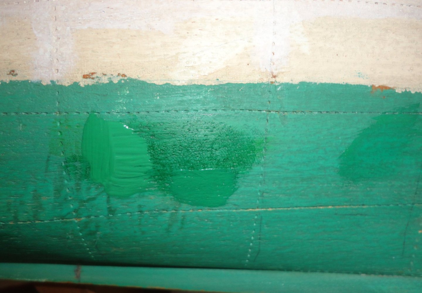
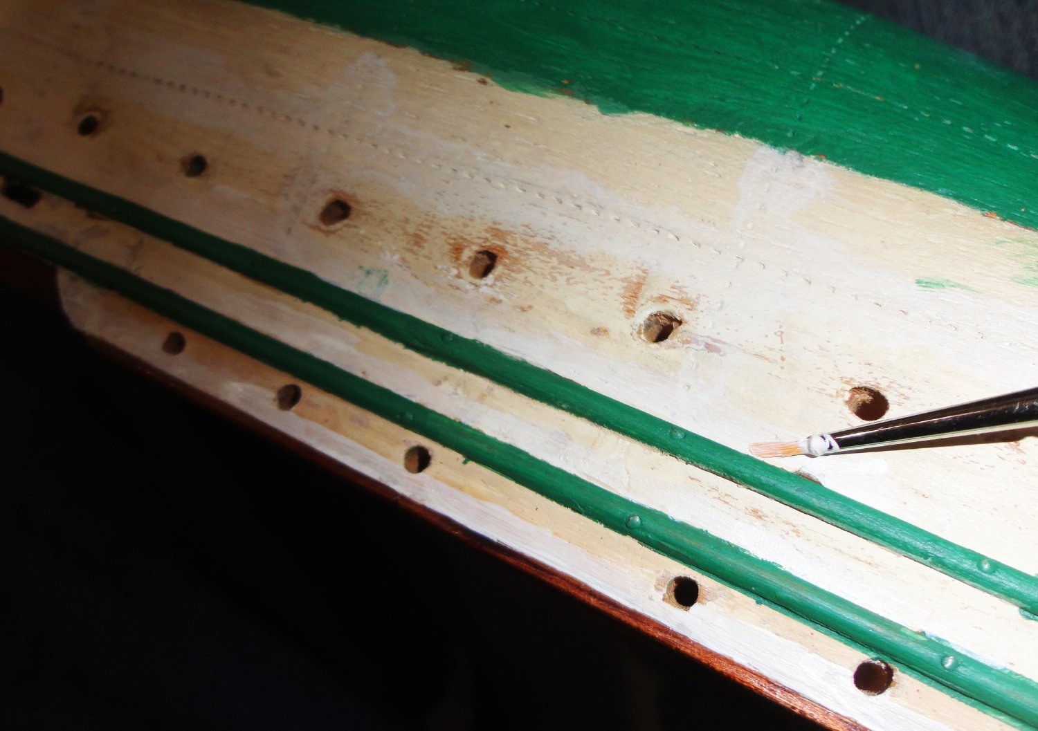
Scotch tape was used to mask the wales, since it will be easier to 'fill-in' the gap between with a fine liner brush.

So far so good. The tape was stripped off before the paint set to avoid any peel-off, and there were few slops. Being right handed, the liner brush was used from the right going all around the model on one side of the wales before flipping the model over to tackle the other sides.

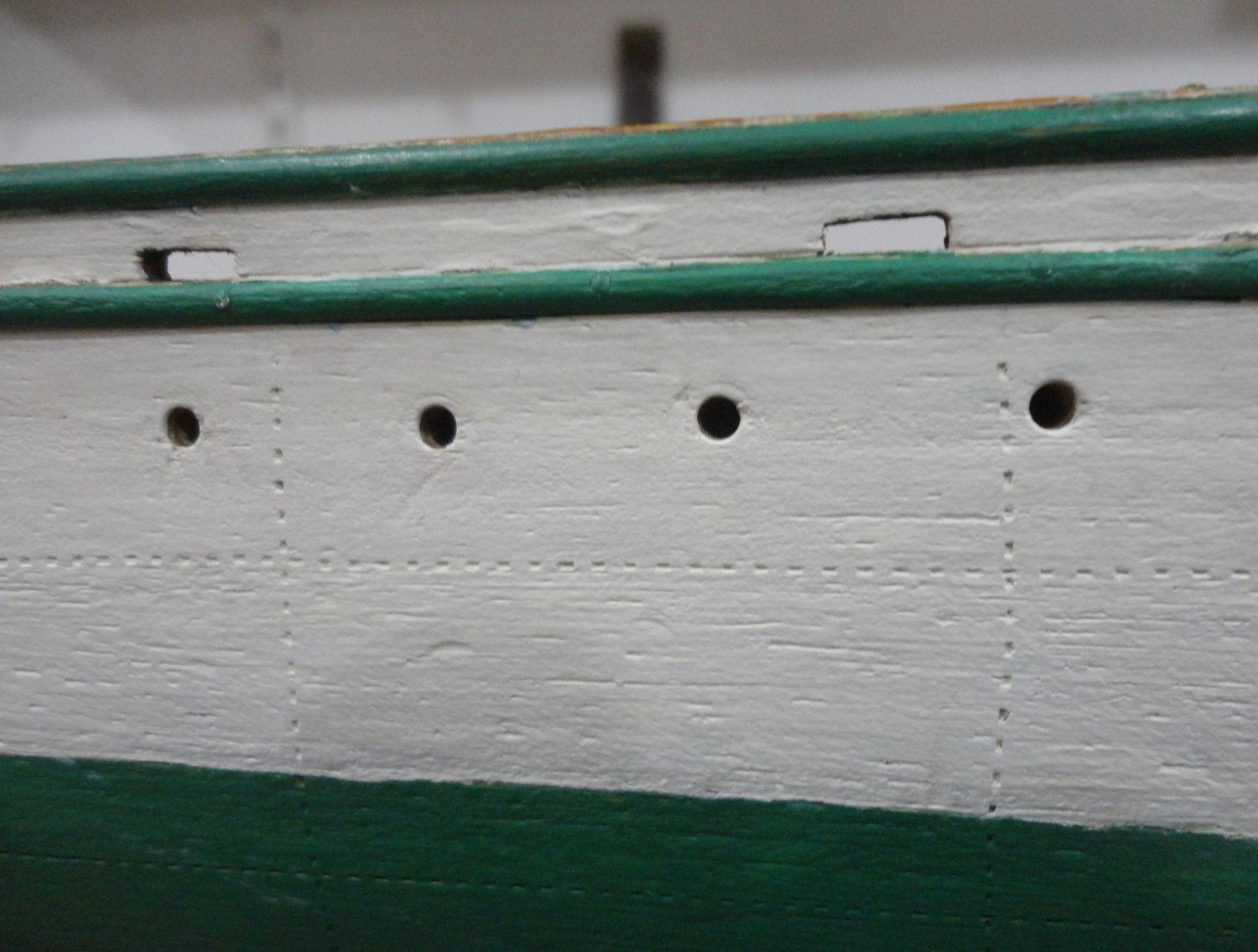
Below shows things looking about like I wanted ... but prior to the re-installation of the port hole surrounds. Yeah, such surrounds were not on the original ship - but again (in the spirit of restoration) they are to be added since 1.) the perimeter of the holes on this hull are a tad irregular and 2.) a lot of time was spent re-conditioning and regularizing the brass grommets.

Some of the grommets were snug, but some almost loose. So to prevent future loss, a dab of glue went just inside the portholes, then after placement each grommet was set with the grommet setter - later inverted to tap the edges flush as needed. There is a certain charm to them.
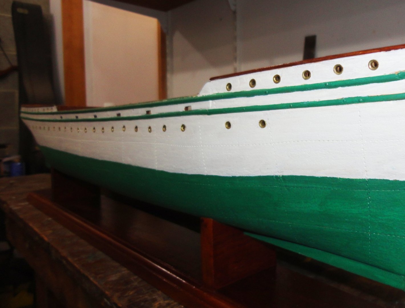
I see the slight wave in the waterline, so after this picture was taken, it was straightened with a liner brush - easy enough to do. Peering down the length of the hull revealed a few other places for slight adjustments in the line - now made.
- Glen McGuire, davyboy, Javelin and 1 other
-
 4
4
-
-
I get the 'scale inaccuracy' (what were they thinking ... or were they thinking at all?), as I picked up a Airfix 1:72 Golden Hind (one of their better models) to compare with my 'old stock' (pre fire) Mammoli GH stated to be 1:54 on the plans ... but the hull sizes are virtually identical. (I think I figured the 1:72 was about right.) These are part of my "kit collection" (AKA 'stash'), which isn't too large really - 10 plus three 'parts kits'. I do like looking through them from time to time.
- Ferrus Manus and GrandpaPhil
-
2
-
-
-
$1,500 before duties, shipping, and extra stuff to correct or upgrade seems steep - as well as (my guess) the 2 - 3 years (or more ... unless retired and with a lot of available time) one might take from soup to nuts. But is money is plentiful and the desire is there - why not? There are many who take on the Victory, but I wonder how many get finished - and in what fashion. Hopefully a builder won't use nearly white rigging line for the ratlines and deadeye lacings. 'Always thought models so completed looked odd, as contemporary artwork and 19th c. photos show dark lines for all the standing rigging on sailing vessels. OK, someone used tan line on the present-day Victory on exhibit ... couldn't say why.
-
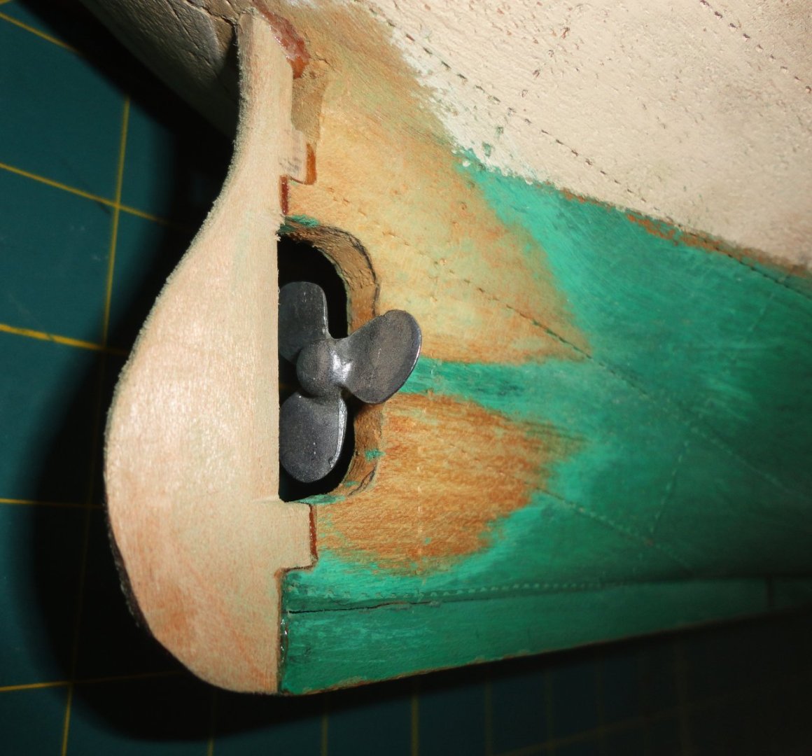
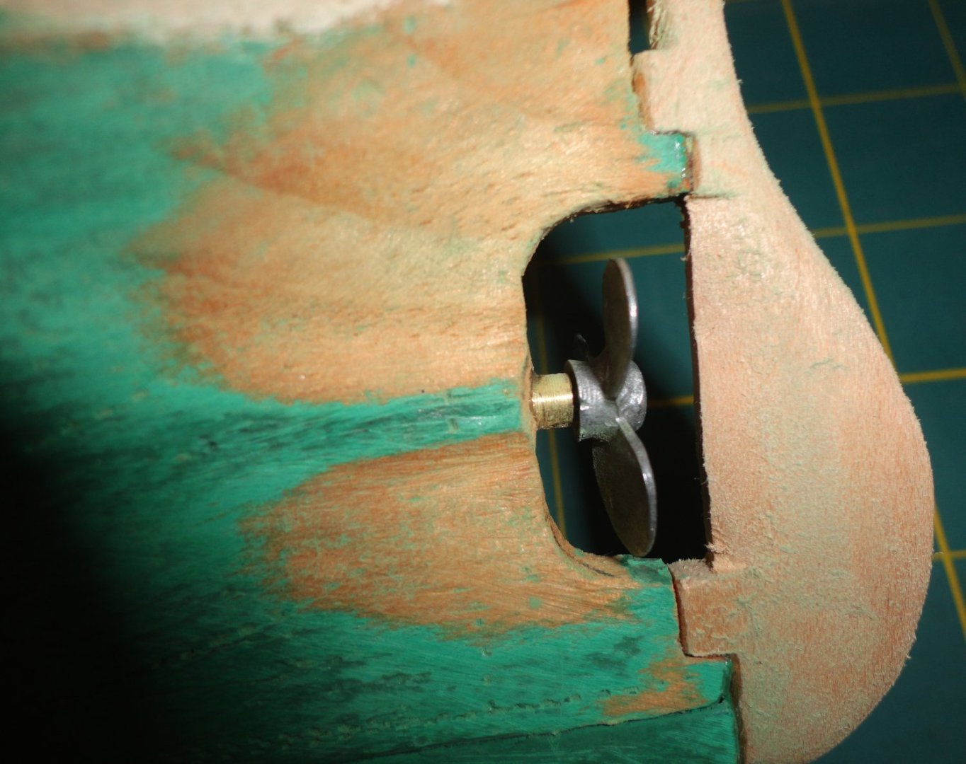
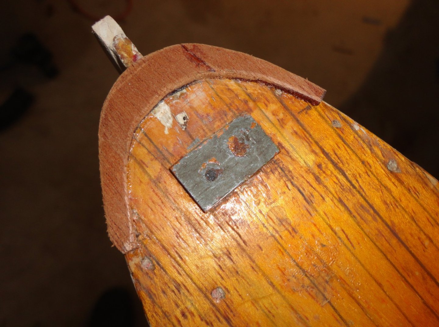
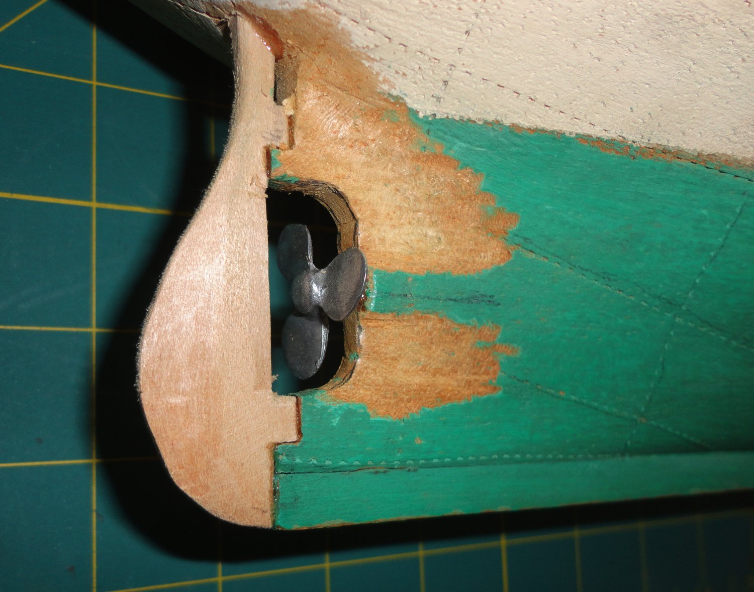
'Looked at the stern below the waterline after the rudder and prop work, and thought the thickness of the flat ahead of the prop didn't look right ... way too wide for effective propulsion. Good enough, perhaps, but I thought to myself, "Johnny, seriously ... you can do better." So I got out a couple small wood carving tools and roughed-out better streamlining,

Then the area was sanded and I could see an improvement ... when painted, it will then be a little better then 'good enough'.
On the other side the difference between the soft early growth and the harder ring growth started to show. It then became apparent that the difference in the resistance to pin pushing was due the variability in ring distribution and angle - easier to push pins between the harder ring deposits. Perhaps then the hull was carved from a single block of moderately dense pine - not the fast-grown stuff farmed in recent times for building houses.
Our first house was built in 1927, and when doing a little remodeling I discovered how hard a stud cut from older growth with tight ring structure can be. Framing timbers then were far stronger than what is used today. The wooden hull of this restoration seems to be something 'in between'/
- mtaylor, Glen McGuire, Keith Black and 3 others
-
6
-
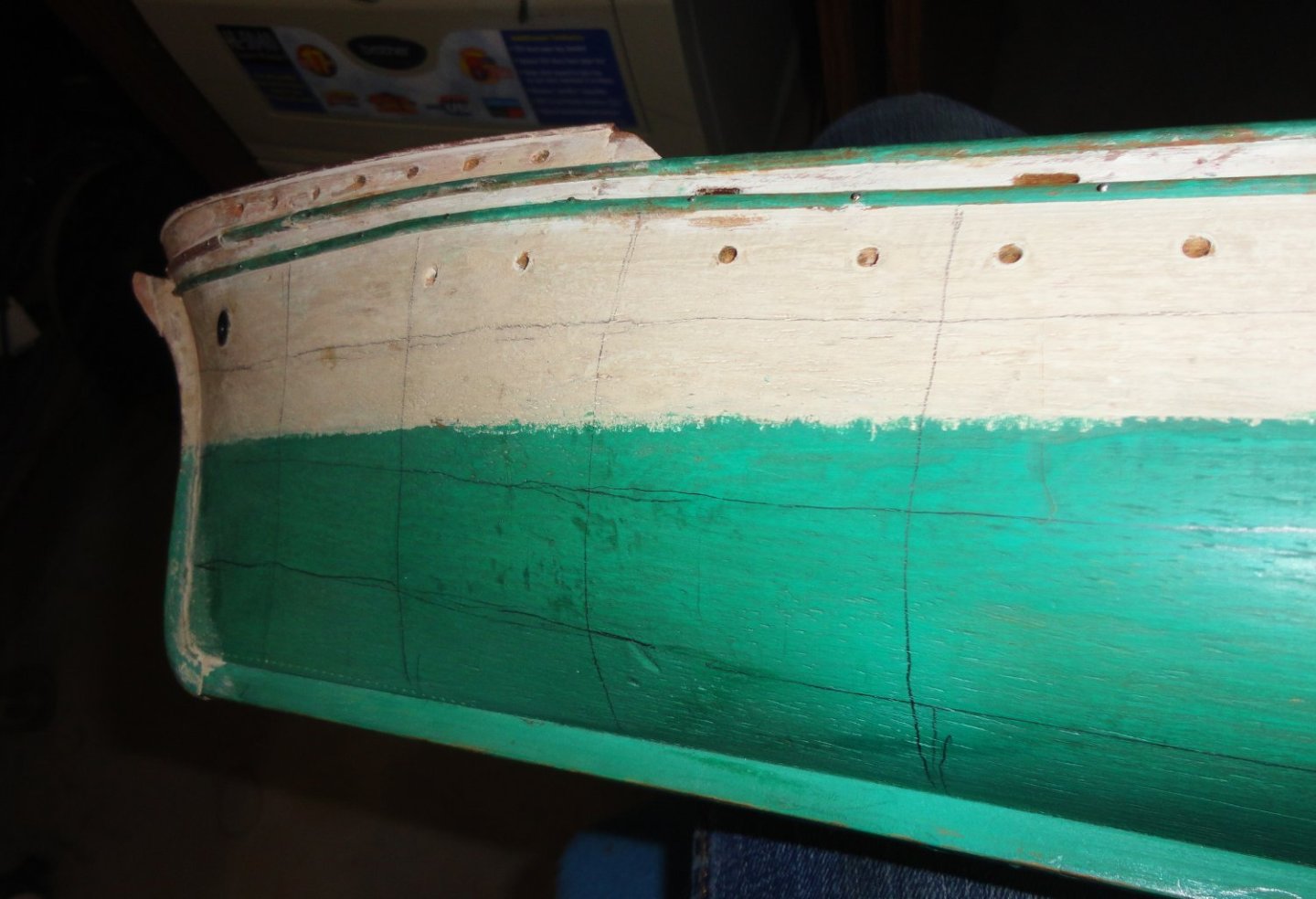
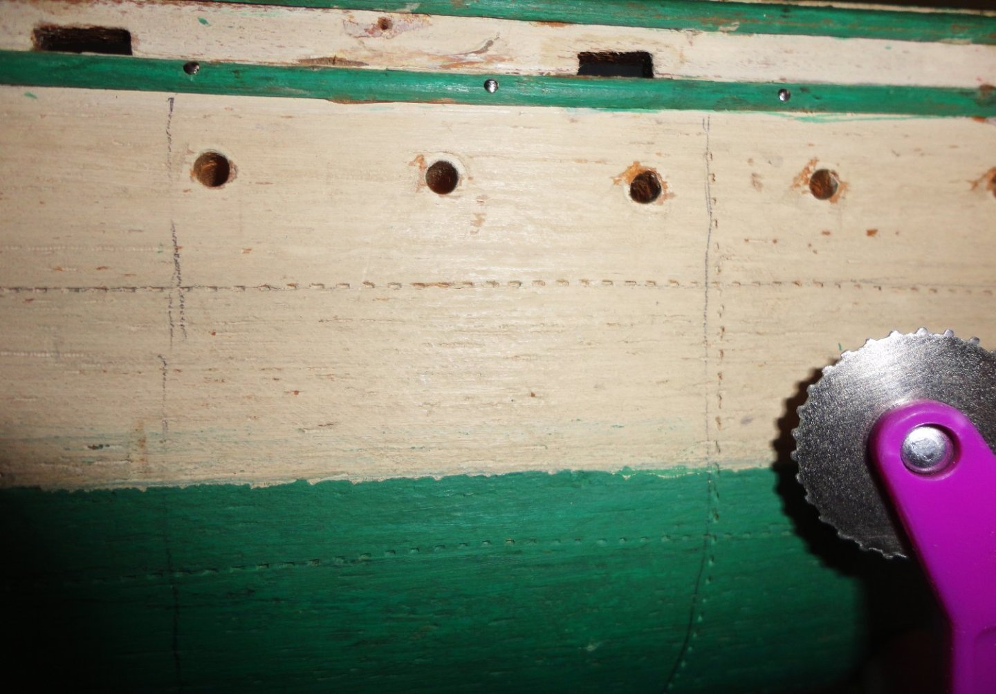
So I thought it was time to mark out (by eye) the main rivet lines discussed earlier in the restoration ... but only using the modified ('nubbed') pattern wheel, with no actual rivets (out of scale) or other fiddling (tooling) with the hull. These prove to be very small indentations to suggest the riveting on the original, noting that there are other weld lines that simply don't show from a distance. Holding a mechanical pencil, other parts of the hull were used as a guide as the horizontal lines were drawn. The verticals (the Pennsylvania 'Dutch' hereabouts pronounce it werticals, almost like 'where (it) tickles', - the v having a w sound. I used to work in a fabrication shop among many PA Germans, and asked one how he'd say valve ... what he said sounded to me like walf.) ... anyway, the verticals were spaced at about 2" intervals (roughed with a scale) and descended by hand. Sometimes one just has to jump-in and do something - but I suppose if one either wanted to be super-accurate or to compensate for a less-than-steady hand, one would tape out each line individually.
I didn't want to fuss that much and thought NFW, I'll wing it ... they're only mere indications that will also be painted over. The Admiral asked me about the acronym NFW, and I said that the N stands for 'No' and the W stands for 'Way".
Next the wheel was used with 'just the right' pressure learned from practicing near the keel. From pinning things in various places on this old wood hull - which I like working with enough to contemplate carving hulls for future models - much of it may actually be a dense basswood with maple blocks glued as the forecastle and the poop deck, since those areas were much harder to push a pin into. The hand drill was just used a little deeper in those areas. The weather deck has the same grain & appearance as the higher decks, so may also be an applied piece of wood, albeit thinner.
The divot lines were straighter than the rough pencil guides (corrected in-process), but there are a few places with some drift - no matter.
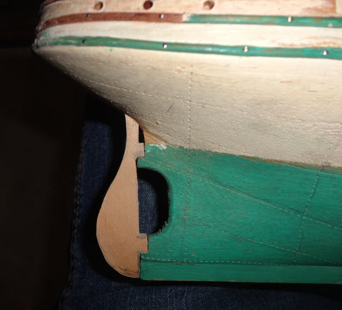
Now I thought it time to rough out a rudder from basswood stock about as thick as the keel. The angle on the model is a bit off, but that will be filed/sanded for improvement.
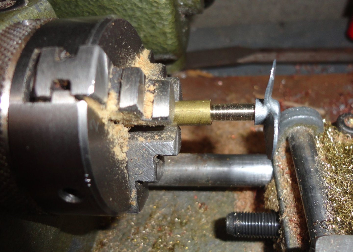
As mentioned before, I'm using the OcCre Endurance 3-bladed prop that will be suitable for this restoration - the original prop on the model was a miserable piece of tin cut to have 3 blades. To position it properly in the prop-space on the model, I decided to cut a shaft segment on the Unimat - center-drilling and end drilling a right-sized hole (2.3mm, which mic'ed about .092) for the pin on the cast prop to fit into. The diameter was made to be less than the hub on the prop.
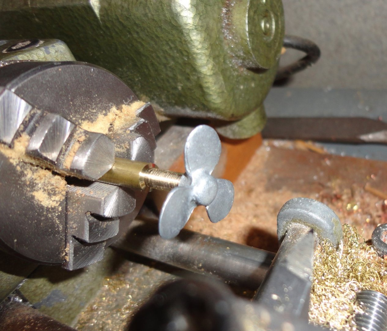
Below is another view prior to cut-off.
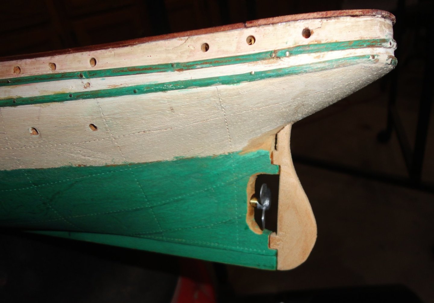
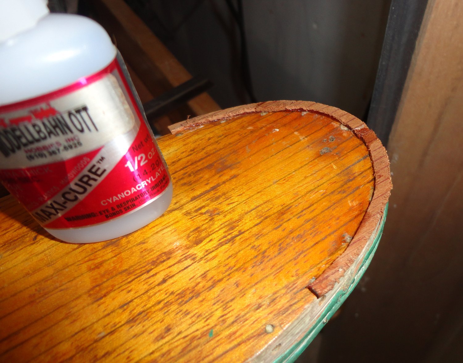
I picked a number drill just under the brass shaft and twizzled it by hand with care into the end grain of the hull (after center punching lightly), and test-fitted for effect. There was a bit of filing and shaping to correct the angles, and ended up with something my eye thought 'good enough'. Then everything was CA's with gel (one at a time) and 'kicked' with dabs of accelerator.
'Guess it's good enough. Like the Coach told the Jamaican Bobsled team in the movie 'Cool Runnings', "Winning a medal is a fine thing. But if you're not good enough without the medal, you won't be good enough with it."
- mtaylor, davyboy, GrandpaPhil and 3 others
-
6
-
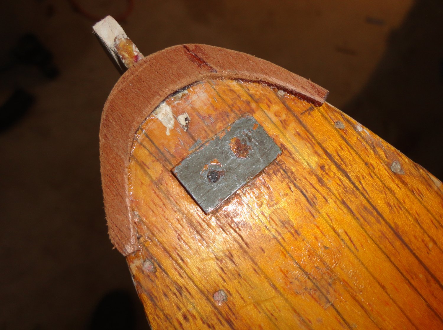
A trim piece is absent on the forecastle and poop deck - one seen in other GF models and also in photos. Bending the long dimension just won't work on the curvature on the ends, so paper patterns were made and end segments cut out on a jig saw. Thicker CA was used - first applying around the periphery of the deck, the wood (cut slightly oversized, since it can be easily abraded later) laid on (held with finger pressure) - while the other hand delivered a dollop of accelerator with a dental tool. SHAZAAM, the CA set-up really fast, and bonded the wood to the varnished deck just fine. The add-on piece was still fragile and cracked in a couple places, but the CA bonded them. There is a slight 'sweet' smell of the bonding reaction, which is also exothermic. As said elsewhere, the 'thin' CA is wicked stuff that wants to go everywhere ... but there are a few applications for it.

Another pattern was made for the bow and the wood installed the same way.
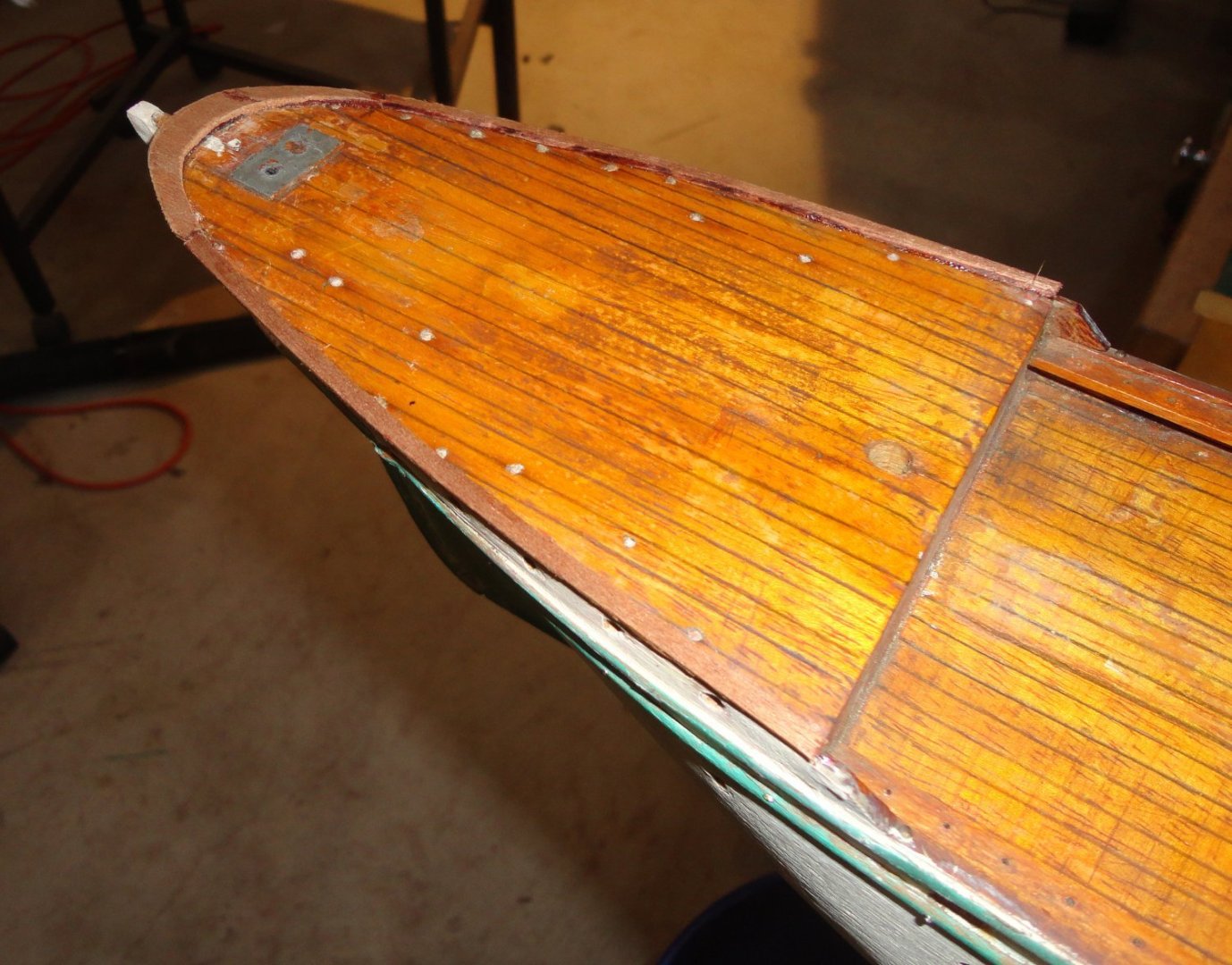
Here is a picture of the rough sanded stern. I see a hull nick (tear-out) that I hadn't filled before - no matter, that is easily accomplished. A rudder will be fashioned from the same thickness of basswood used for the bow repair, and I have a suitable prop to install ... the one supplied in OcCre's Endurance kit, as a two-bladed prop has already been obtained for that future build.
Below is a shot of my inexpensive Harbor Freight mini saw ... and the deficiencies inherent in a budget tool were mentioned in another MSW thread. However, the make-do fence clamped to the table seems to work for sawing the width needed for the rest of the top rail (wale? .. whatever).
Below are shots of the CA'd wood added to the bow and stern. 'Seems OK to me.
I'll even the color over the plugged holes with amber shellac, and the added wood as well.

- Keith Black, _SalD_, davyboy and 5 others
-
8
-
I've seen other builds more or less 'out of the box', and wonder if (as OcCre instructs) the middle portion of the yards (where flat wood is bonded around the yard to make a polygon) appear a little 'fat'. One could file flats around the middle portion of the yard prior to gluing on the additional wood, so the diameter in that area would be reduced.
The studding sail booms might be a tad oversized (thus the rings for them also), and are they normally placed atop the yard? I simply don't know but generally see the booms near the bottom of the yard, perhaps slightly aft. Foot ropes might not descend as much as shown, and deadeyes seem to be typically dark in color.
That's all the details I care to ponder, as your work is significantly better than anything I've done. KUDOS !
-
Have the pecan slab-cut asap and stack with slickers to dry in a covered space (garage or shed) over the winter, then move the stack indoors (adjusting the spacers periodically) for a year. Dap the ends with melted wax to limit checking.
I was given a freshly cut 3' long x 8" diameter apple wood log by a friend some years ago, and at the time had a radial arm saw with a head that could index 90 degrees, So I got fancy and figured out a pattern to maximize quarter-sawn pieces. The whole house smelled like "Christmas" the day of cutting. The drying was uneventful, and half of the stash remains.
-
Your pair of ships are beautiful ! Congrats on completing both .
- AJohnson and The Gimps Chimp
-
2
-
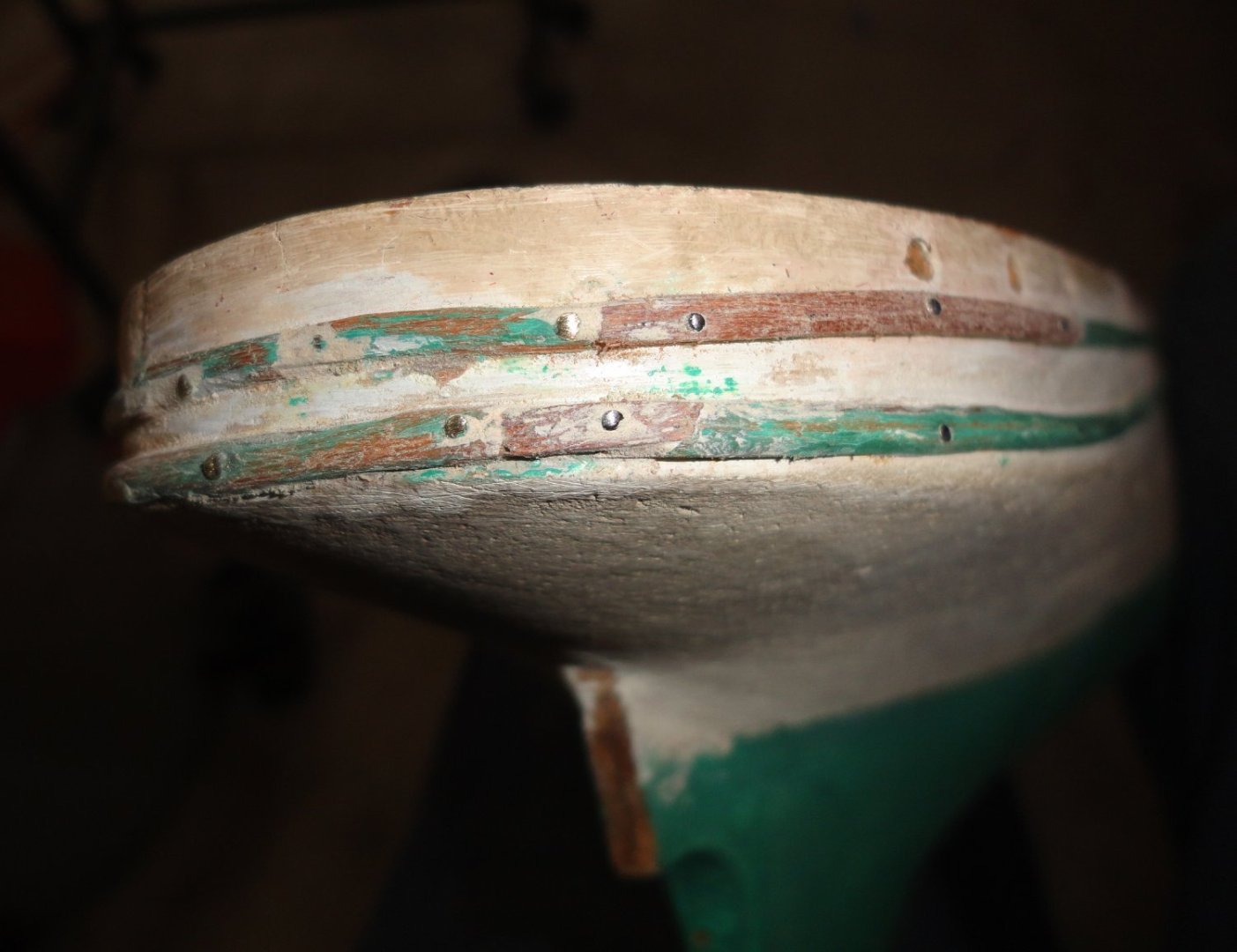
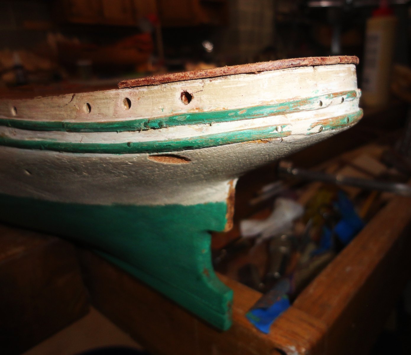
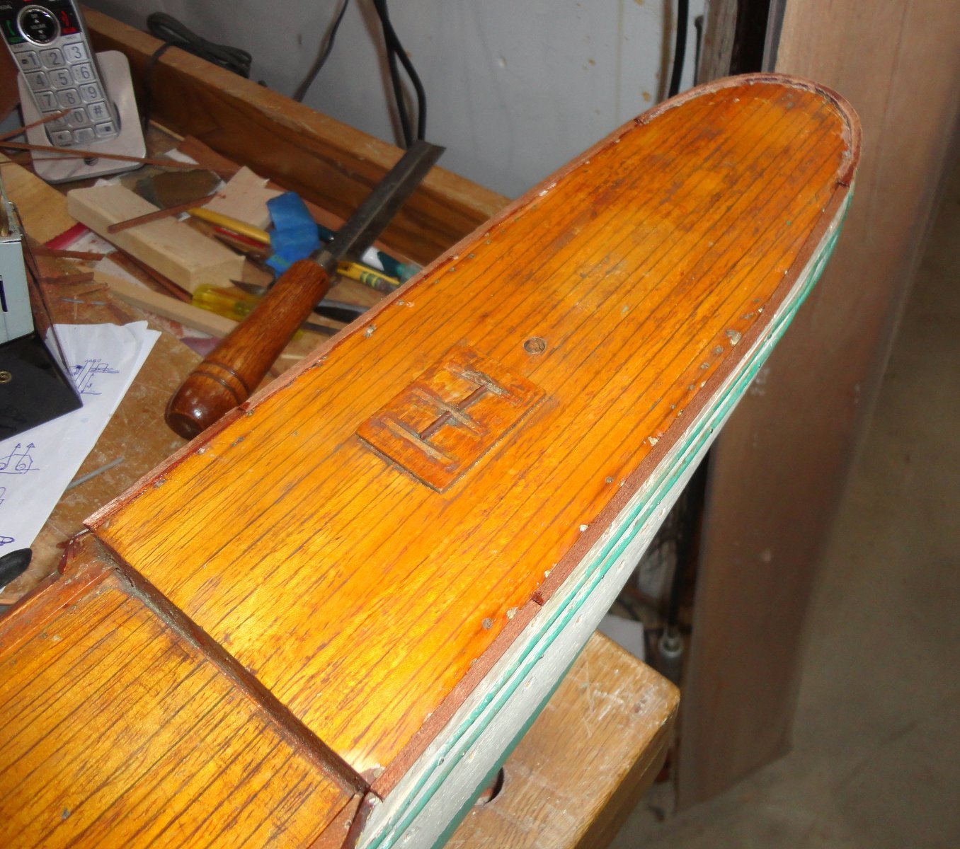
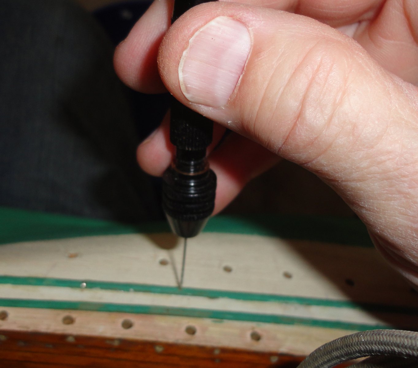
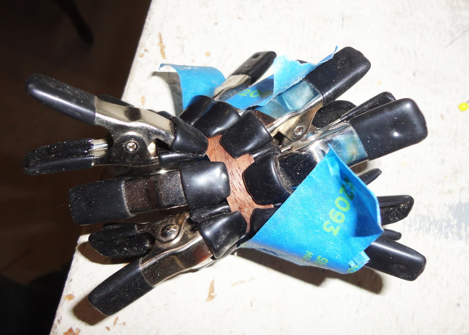
Second post of last evening's work. While the veneers were drying, I went ahead and pinned down loose wales - something practical with a solid wood hull. So not to split the thin wood, a pilot hole was hand drilled, but not as deep as the pin to be used.

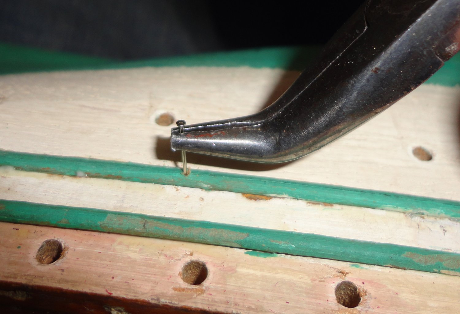
Bent pliers got the pin started into solid wood below, and could sometimes nearly seat the pin.
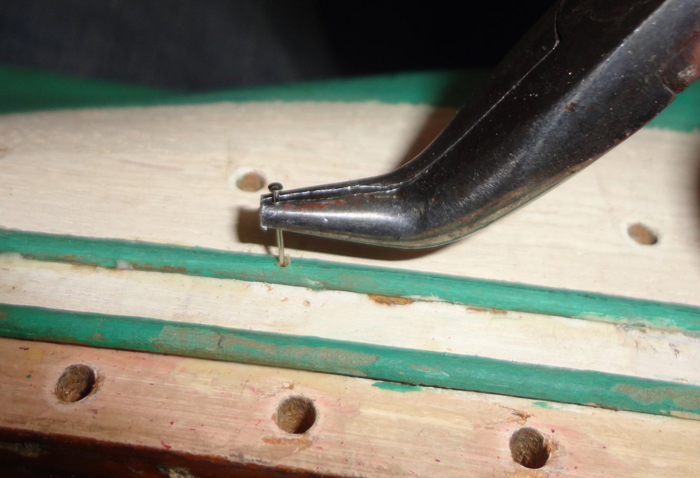
A tap or two with the planisher was followed by a roughening with fine sandpaper so paint will adhere.
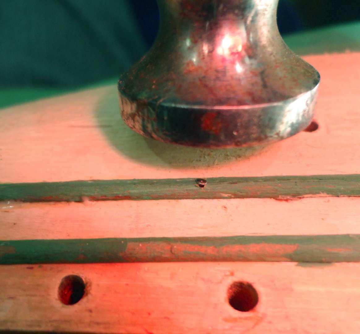
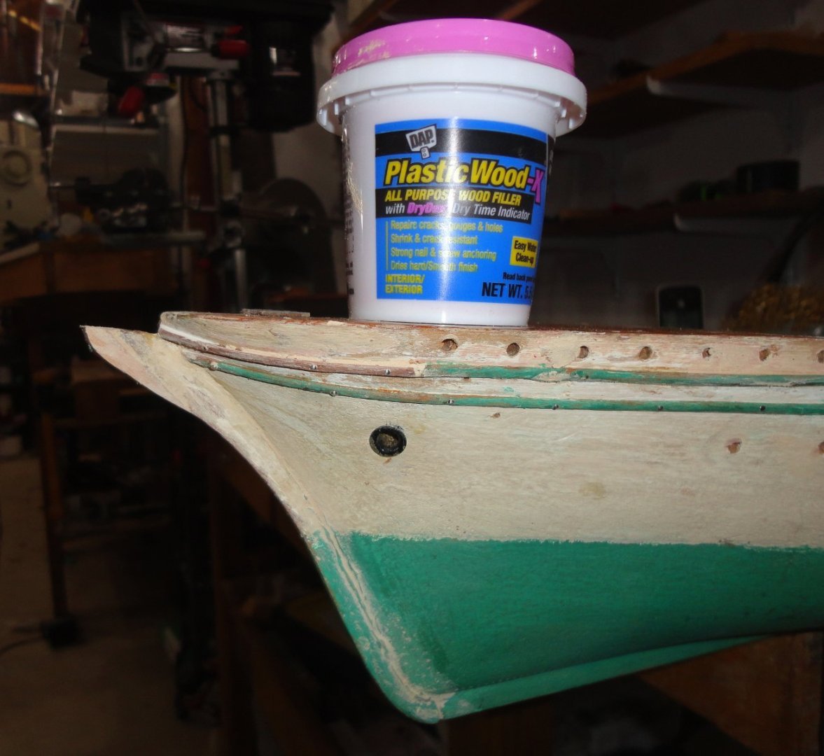
Then replacement strips were added where the original was lost. I decided to try a new filling compound - one that doesn't 'smell' of solvent. I found that solvent-based wood putties can dry pretty darn hard, and can be difficult to sand.
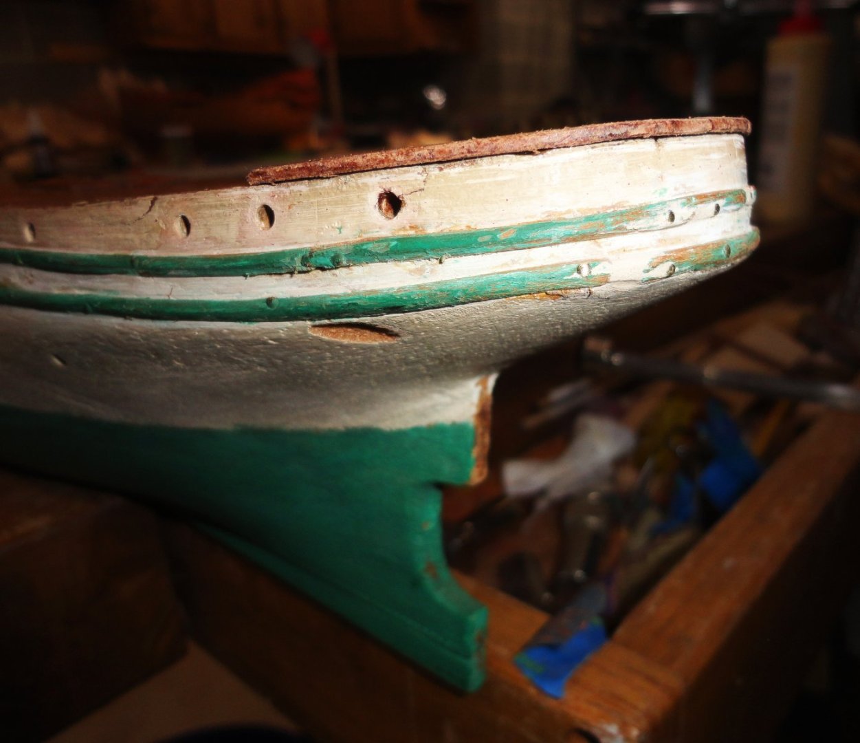
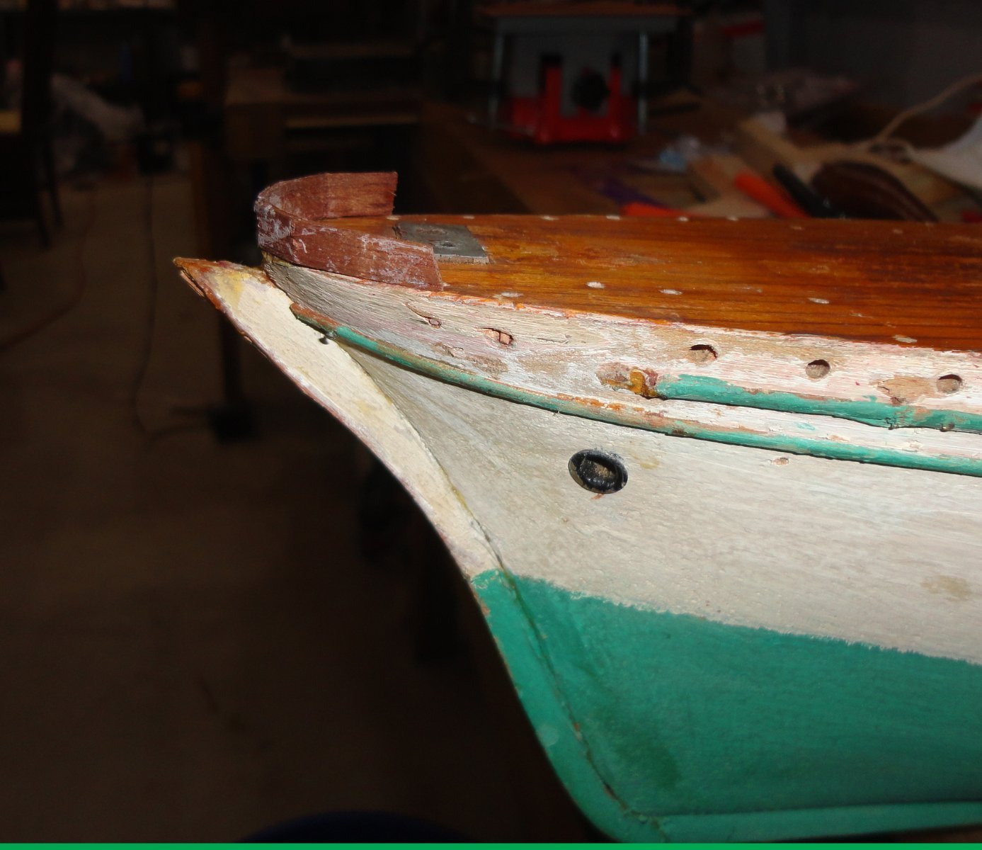
This new stuff cleans-up with water (that which has not dried). The dried compound sands a lot better than stuff I've used before, as it is not as hard when dried. You can see an add-on to restore the original shape of the prow, which had been damaged in the past - presumably when the bowsprit broke. The new wood was glued on and pinned to the underlying wood - then filled.
Now enough time passed that I unclamped the piece formed ... it still had a little 'flex', so it could be adjusted. After some sanding and shaping, it about what I'd been looking for.

- mtaylor, gak1965, Keith Black and 4 others
-
7
-
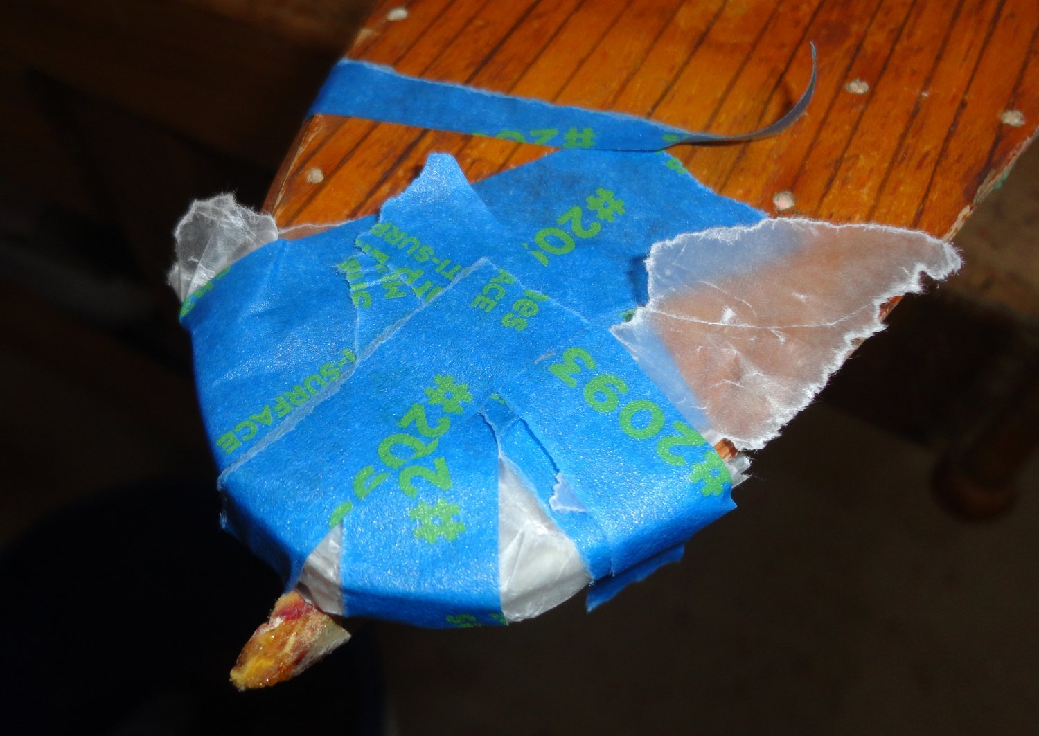
Sometimes a few days can go by with 'too many other things' to do, resulting in no progress at the shipyard. But then I can do a bunch in three hours ... and the latest 'bunch' is split between 2 posts. Now there are differences in configuration from the GF1 (as built), a couple of GF1 modifications and then the GF2. From the pictures of the original I can see, there is some metal shielding at the bow, so I wondered if I could bend a piece of planking into a parabolic shape to go around the extreme bow.
A spare scrap of mahogany from another kit was soaked and heated with an iron before trying to get a bend in various ways - including chewing. The bend was too extreme, so I tried boiling the plank in water for a while - and this did soften it enough to bend (with just a few snapped fibers on the outer surface. I figured that the bow of the model could be a form to tape the softened plank to and let it dry. Due to aforesaid cracking, wood glue was applied to both sides and covered with wax paper before taping.

When untaped, it didn't look too bad ... but it was entirely vertical in relation to the deck, where the original guard is flared to match the angle of the hull side in that area. Something else had to be tried, but below is a shot of the first effort.

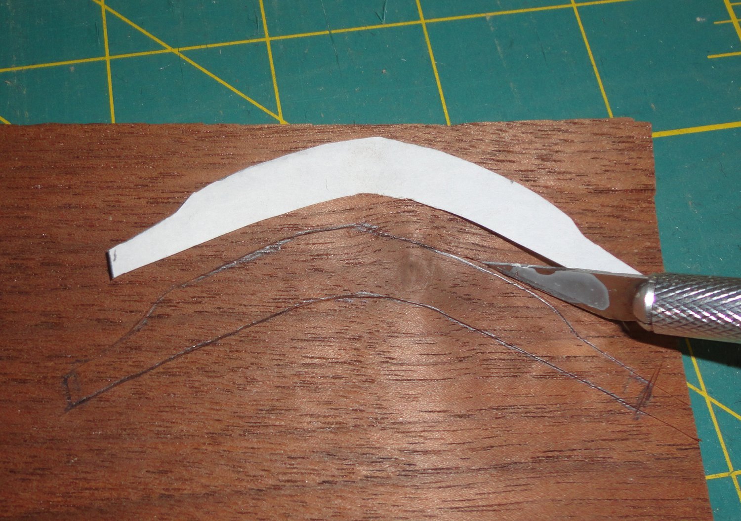
A roughly parabolic cut was made into paper (trial fitted & trimmed as needed to the bow.
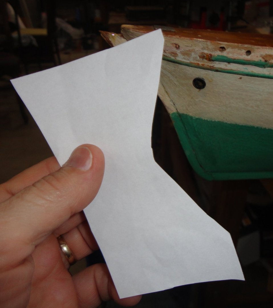
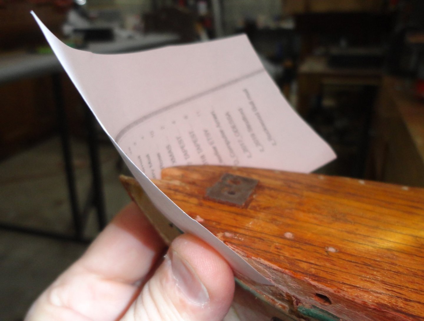
I decided to cut two pieces of ordinary walnut veneer (the thin sort), as thin stock can ben a lot even before heating/soaking.

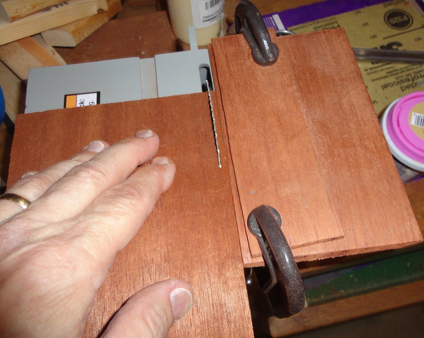
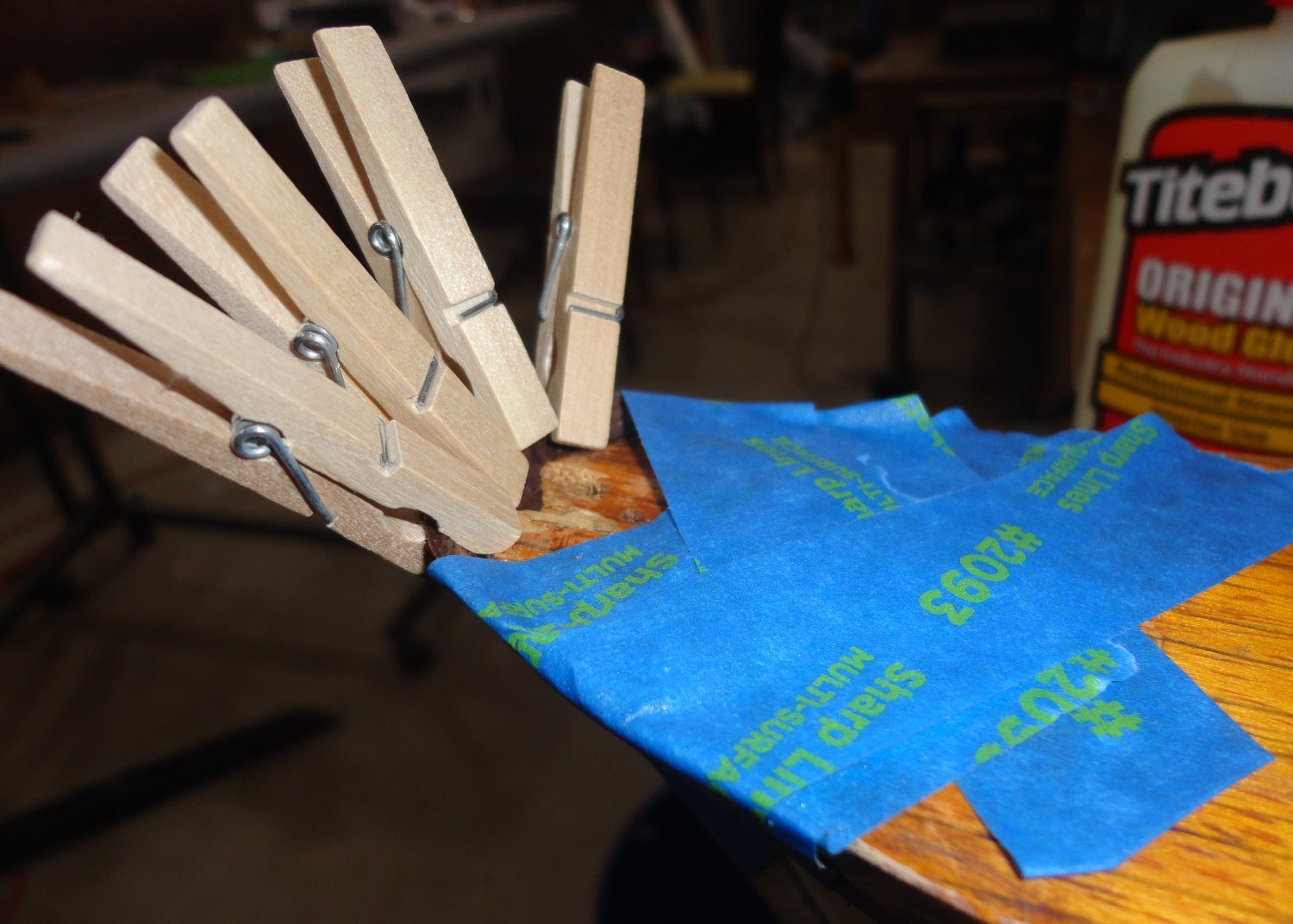
These pieces were boiled and got VERY flexible, so some wood glue was put in between before using the bow again as a caul ... actually, as many layers of veneer can be used as desired for thicker pieces - and when bent to the caul (form) they all shift as needed. Trimming is done later, so the parts should be oversized when glued.

I found later that the wetness of the stock made most of the glue 'seep in' to the parts, and the bond was not good. So in a nearly dry state (having been pre-formed), they were still somewhat flexible, so fresh glue was put in between - and then many clamps were added (plus a little tape to slightly over bend, since there was spring back).

It a perfect Indian Summer Saturday, and I must take the Admiral on an excursion shortly, so I'll finish last evening's progress in the next post. If I'm lucky, perhaps we'll have a pleasure cruise this afternoon.
- mtaylor, Glen McGuire, Keith Black and 2 others
-
5
-
-
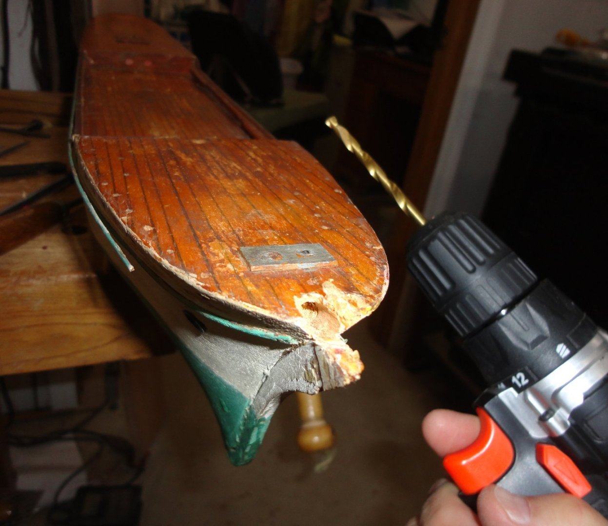
While drilling for the bowsprit, a couple problems arose that were resolved sequentially 'on the fly' without even thinking to document them. Needing both hands for a lot of stuff, certain things just don't get photographed. It wasn't just a matter of drilling away, even after squaring the surface with a fine saw. The drill bit needed kept wandering without biting - so I thought a much smaller pilot would worth trying.
The pilot did grab, but soon wandered off-center - so that hole would be worthless since a larger drill will follow a smaller pre-drilled hole. What I should have tried was to use a prick punch (or use a nail) to provide a center before drilling the pilot. So a small 'U' gouge for wood carving was used to incise around the desired periphery (ignoring the errant beginning of the pilot hole) so it could be dug out in bits. Being end grain, the excavation had to be done a little at a time to make a right-sized hole for the full-sized bit that was about 1/8" deep. Then the larger bit drilled with light pressure and stayed on course - reaming out the remains of the original bowsprit still in the hull.
There is a little room for adjustment with the new bowsprit installed, so it will have to be positioned carefully while the epoxy sets (when that time comes). Of course, the hole could have drilled poorly, in which case the remedy would be to turn a suitable plug of wood to glue in with wood glue ... then a second go could be attempted. This is a nice aspect of modeling in wood.
I found a quote from Marcus Aurelius that applies to our hobby (and also life):
“While it’s true that someone can impede our actions, they can’t impede our intentions and our attitudes, which have the power of being conditional and adaptable. For the mind adapts and converts any obstacle to its action into a means of achieving it. That which is an impediment to action is turned to advance action. The obstacle on the path becomes the way.”
-
22 hours ago, Glen McGuire said:
It's fascinating to watch your problem solving skills put to the test with each step! Such an interesting project.
The restoration has indeed captured my imagination at present, and the plan is to proceed - albeit in steps - to completion before going back to the Vasa (the build title has the old Billings Wasa spelling, and that project is being 'busted' enough to get a 'reasonable facsimile' - no great 'accuracy' is possible due to the limitations of the earliest kit). There is definitely a charm to the GF model, and I want to strike the right balance between some modest improvements and respecting the configuration as-built. Once all the groundwork is done, actually finally getting some experience on rigging enhancements ('though with simplifications) should be a treat.
- Glen McGuire, mtaylor and Keith Black
-
3
-
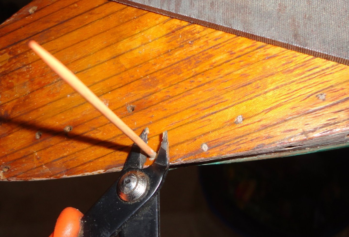
The nail holes are being filled ... I trim off the end of a toothpick and file to make it more cylindrical (like the holes - which may have been drilled first just a little smaller than the nails used fore the stanchions), then trial fit before dipping the end in titebond and filling the hole.
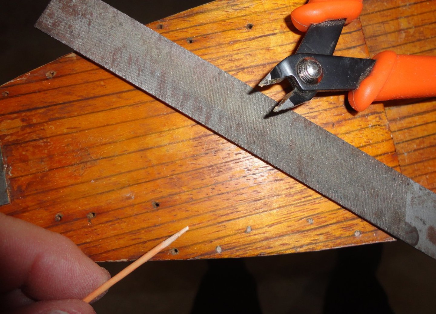
Step 2 is to flush cut.
Step 3 is to tap lightly with a planishing hammer, and just a tap with the nub on a grommet set if needed.
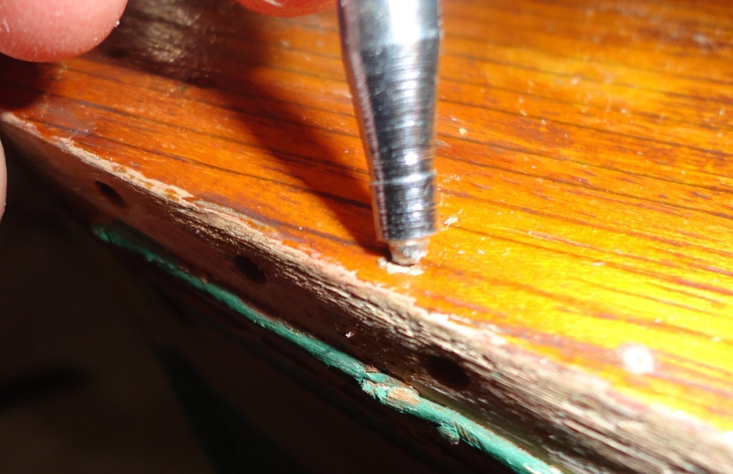
I'll touch up the color with shellac, which will also penetrate the end grain of the toothpicks. The builder's hole pattern (such as they are) will be followed so as not to make any more holes in the deck as necessary.
- Glen McGuire, _SalD_, mtaylor and 2 others
-
5
-
For what its worth, the Austrian Unimat SL from my Dad (he really never used it) has been handy turning and boring small, occasional work in brass and aluminum, but the main drawback is that it is underpowered for steel - unless the diameter is small and very light cuts are made. Changing over to the milling arrangement seemed too much effort. (I have done milling odds and ends on my drill press with a stand equipped with a cross vise.) The four jaw Unimat chuck was used for odd sizes, but centering was always a pain - so stock had to be trued. Once I got hold of a used 3-jaw universal chuck, centering was automatic for round stock ... small diameter stock passed through the head entirely.
If I was going to be doing a lot more metal work (which I'm not) I'd look for something a little more substantial with the power to do steel with decent cuts.
-
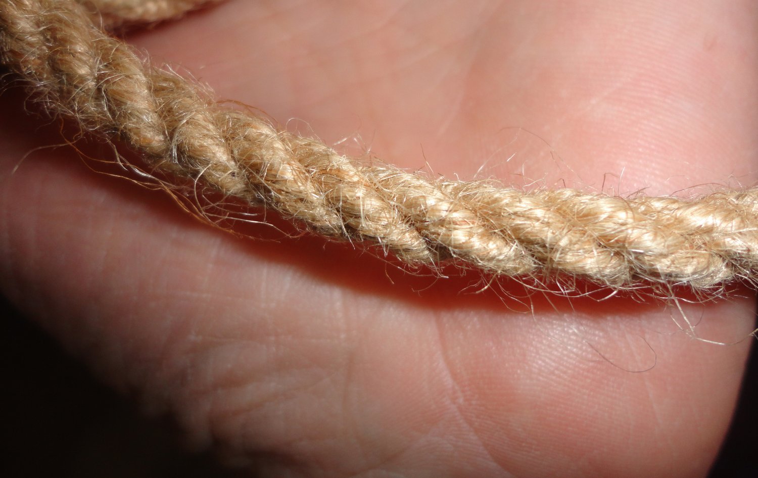
I've made aprox. 3/8" diameter rope for demos ... this size seems to happen 'naturally' by using twine of either sisal, jute or hemp. Sisal is the worst for little 'bits' sticking out, jute approximates hemp - but hemp (the best) is also expensive. Three lengths of twine are strung on each of the three turning hooks for ordinary rope, and the counter twist is regulated by the rope maker's 'top' ... or by reverse cranking in other setups. As you can see in the photos, from a foot away (the first picture), the jute rope seems minimally fuzzy. But get in to a couple of inches away (the second photo) and it DOES appear as fuzzy as your rope.
From 6 feet away (72"), you don't see anything ... and at 1:72 scale that would be merely an inch away from scale rope. Ergo, 'average' kit rope that looks fuzzy from an inch away should not be used ... nicely made scale rope passes the 'inch away' rule.
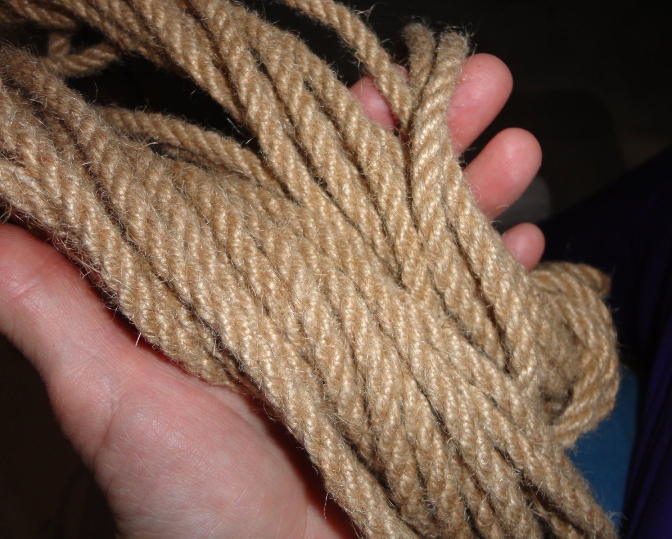

BTW, I found that using a little bees wax on the twine reduced the 'fuzziness' of 3/8" rope by about half.
- Keith Black and mtaylor
-
2
-
If hooks are made of metal (whether wire of P/E), the eye should be able to twist 90 degrees with 2 pairs of pliers (and deft hands) once without breakage. Don't over-bend or bend more than once in order to avoid work hardening of the metal. If the eyes are plastic, then there may be a way to warm them sufficiently (without melting) to allow for a similar 90 degree of the small eye ... once cool, the shape should be stable.
-
As is often the case, you get what you pay for - so if seems 'too good to be true', it isn't. In a pinch, I bought a low-cost mini table saw from Harbor Freight that had some issues. For one thing, it only came with a coarse blade - not of much use for us - so I had to look for mini blades having a 1/2" arbor hole. This took some looking, and a set of three different blades was found on line to get the one fine-toothed blade needed.
The height adjustment of the blade above the table is crude, but that's not too much of an issue. But there is NO fence - a distinct disadvantage. I ended up clamping wood the the table top to act as a fence. The base of the unit is on the small size, and not nearly as stable as preferable.
So something like a Byrnes is obviously a much better thing to have ... perhaps Ebay might be a place to look for a used one. At one time I was into re-conditioning U.S. Civil War era arms (lower grades, known as 'shooters' - vs stuff to collect), and a man ran a shop on his property where he made a wide variety of bullet molds for antique guns (Rapine bullet mold company), as well as loading dies and other stuff useful for antique weapons. Time passed, and he retired. Since no one bought the business, it just 'went away'.
-
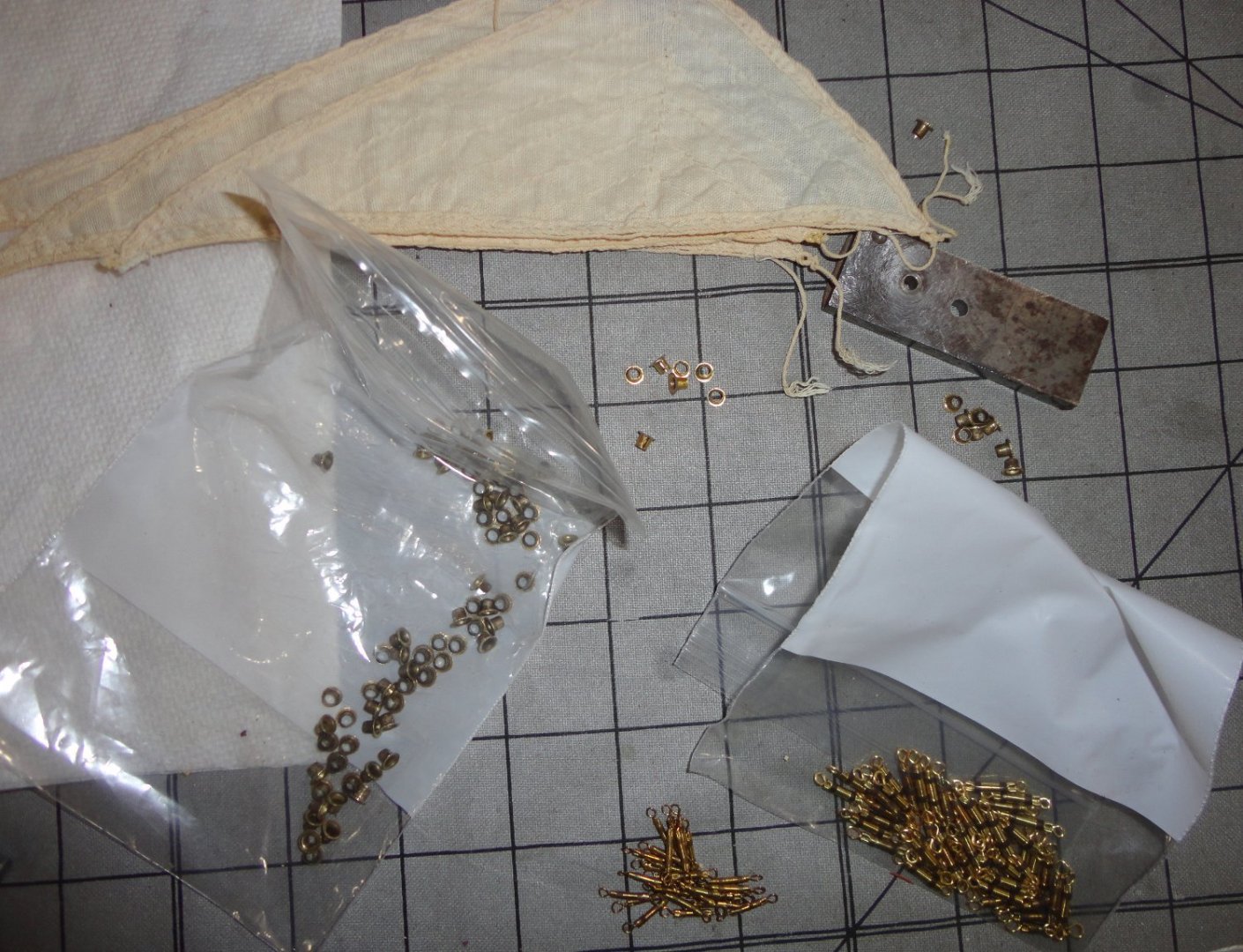
Such a glorious weekend for October in SE Pennsylvania ... and no 'first frost' yet, so all the annuals are still in excellent bloom. Yet it is not to last, so there may be better restoration progress once the cold sets in (at last). I ended up 'spinning' the original eyelets to get rid of any ovalness, and also to reduce the flange a little. Now I'm really happy with them. The lick of the grinding wheel did produce micro burrs, so each was de-burred and planished again to restore flatness ... all 82 of them (not counting 6 spares - 2 of which are already needed).
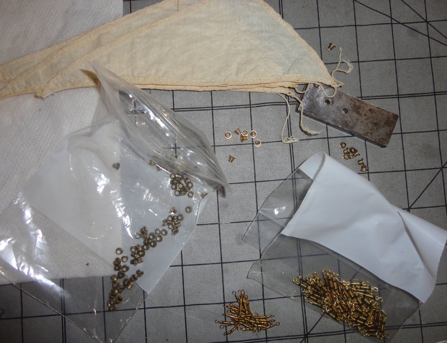
What I seem to be doing is 'kitting' this project as each small bit is decided on and then accomplished. There's a box with the purchased items, and the scratch or reworked items are going into plastic bags. There are sail sets, cleaned masting, 2 sizes of turnbuckles - and the concept drawing for the rigging (yet to be finalized).
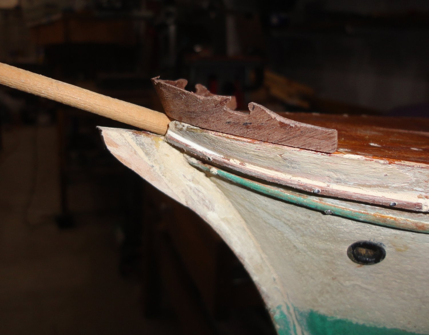
Doing my own 'kit' is comforting, as I've always liked kits - whether built 'out of the box' or modified however much. NOW was the time to grit my teeth and decide what to do with the bowsprit. The concept of joining the original with a rod just won't provide the stability needed once rigging proceeds. So a tapered piece of masting (some top mast) from a parts kit was found, then the last inch had the taper removed on the lathe so it will fit properly into a cylindrical hole to be drilled. How to do that ...
An ordinary bit was selected since the end of the bowsprit is a non-standard size, so I knew 'grabbing' and keeping the angle right would be tricky. There was some tearing at the mouth of the bore, but ... there are always some unplanned things that happen. You can see the 'sprung' trim on teh side, but that will be glued with a little pinning for good measure.
The nail holes (previous uprights for the railing) will be filled with tooth pick and re-drilled for the nice brass stanchions purchased. Before the bowsprit gets epoxied, it will have to have all the hardware mounted and be painted white. Finishing the hull will also be done before mounting the bowsprit, since one done - it is a vulnerable part, and many models (like this one did before) are subject to accidental breakage. Bur just to prove that my eye wasn't off, the stem was test fitted and it looks OK.
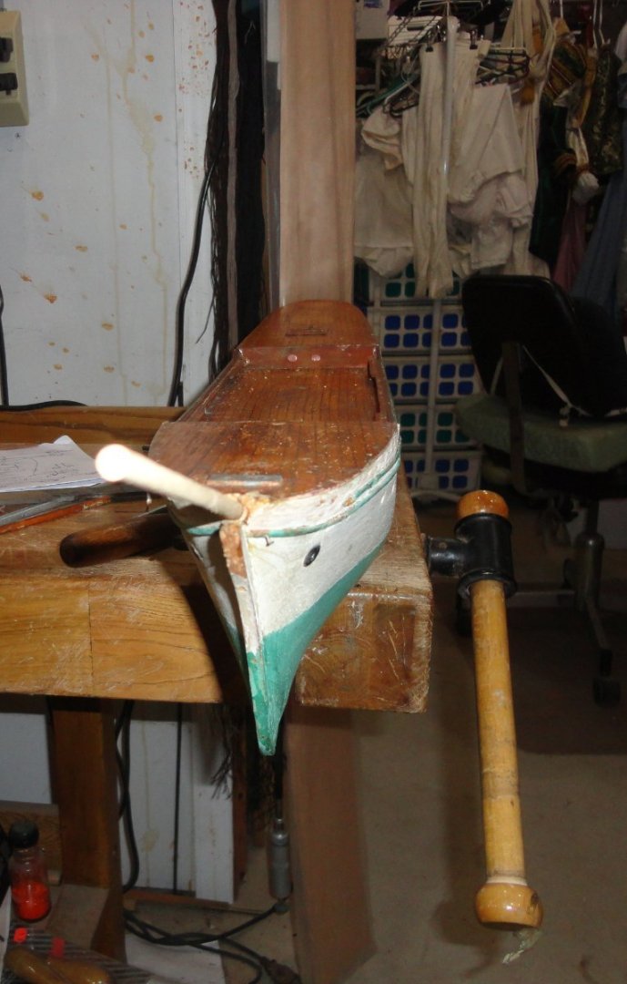
There is work to be done in the bow area as well. The above step, being accomplished, has me breathing a sigh of relief.
The first coat of shellac was given a day to dry before light sanding and re-application. Two more times it was sanded and re-coated. Shellac is 'funny', in that the rough surface of the wood (if seen highly magnified) presents mountains and valleys ... and the shellac coats all evenly (with some absorption the first go-'round) - leaving the same profile. Sanding 'knocks off' the mountain tops, but leaves the valleys slightly filled in. Subsequent coats also tend to coat evenly ... don't even think of 'over applying' to try and "drown" or bulk fill-in those valleys, since that will make a gummy mess.
With each sanding, more of the 'mountain tops' get leveled off as the valleys do finally fill-in. When taken to a planar surface, then building up a thicker flat coat, some wadding inside a twisted piece of lint-free cloth is the applicator to keep everything smooth and even - with the final pass or two done with just a little alcohol alone. This is what is known as a 'French Polish' - like on fine colonial furniture. There is still some natural thickness variation that gives it a finesse - not the thick 'plasticky' look of urethane. And some woods (like mahogany) have a 'shimmer' known as caytoyency - an almost 'jewel-like' appearance. I only go to this amount of trouble on fine furniture.
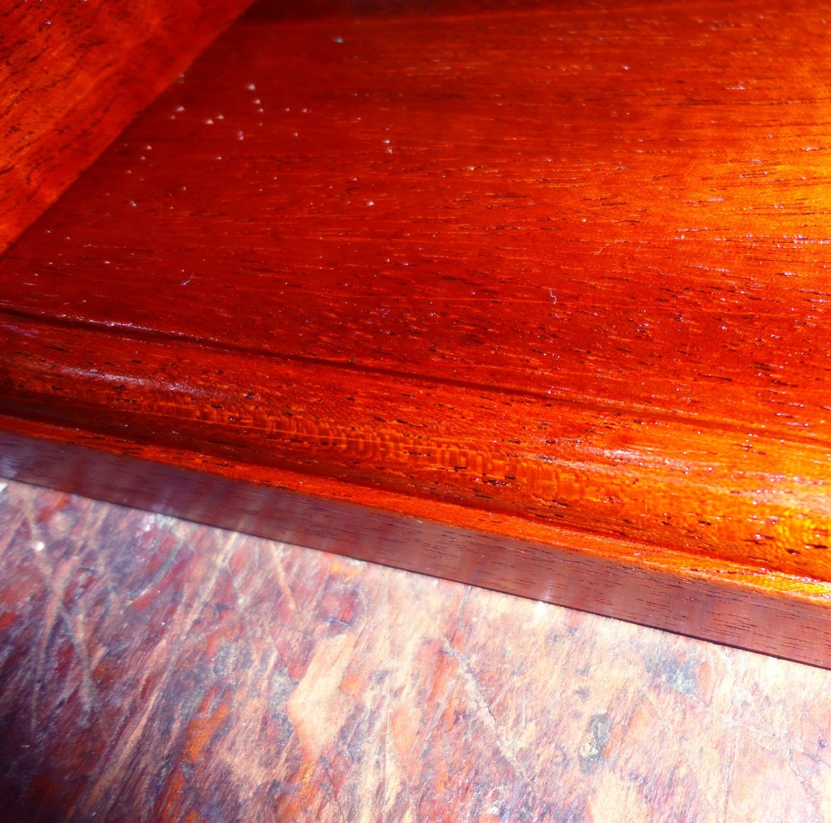
For the stand, I chose to leave some of the grain in evidence ... a little like the best of both worlds. The color is a little off in the picture, and there are some flash reflections in dots or streaks. The wood looks far better 'in person'.

So far, so good.
- Glen McGuire, Keith Black, mtaylor and 3 others
-
6
-
Thanks for the comments on the new stand. A coat of amber shellac was brushed on, 'raising the grain' a little (typical). Once dry, it was lightly sanded and a second coat will soon be on. New-world mahogany is my favorite wood, and less available these days (plus more costly). A French Polish finish is second to none in my opinion. I'll have to make a nameplate.
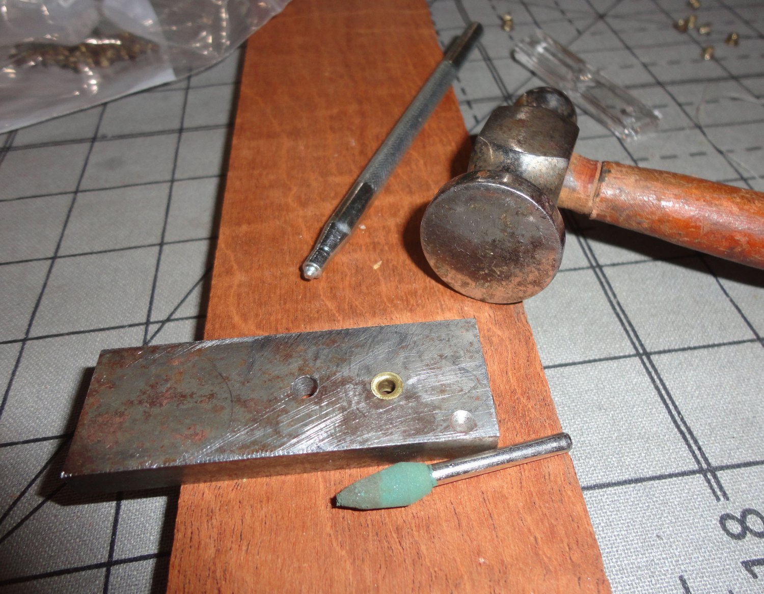
The builder used eyelets as they were, and the degree of flatness varies a bit - so a .125 hole was drilled in a piece of mild steel - with a larger hole for the next size if ever needed. The shank of the small eyelets are about .120 in diameter, so they drop into the hole to set very lightly with a grommet setter (seen in the photo). Then a planishing hammer flattens, a lick of fine sandpaper on the flat plus a little hand burnishing of the hole - and its done.

So when all were regularized, the count was 82 ... but there are 42 potholes per side, which means that there were a couple missing initially that I didn't notice, or I've dropped two along the way (more likely). So the process to alter the modern replacements is to first flatten on the die - which makes for a wider face than the originals. Then I used a shear to cut away the excess (with the eyelet on a mini file shank for convenience), as the brass had been work-hardened by the original forming and then the planishing.
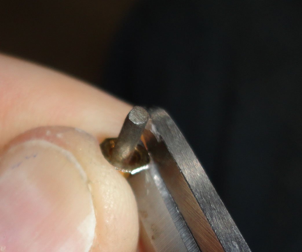
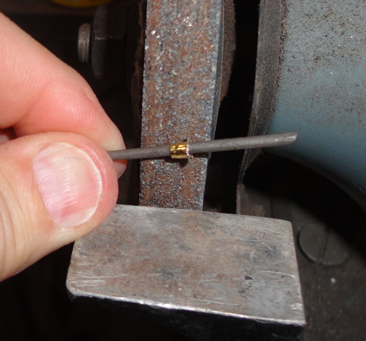
Then the eyelet was given a few licks of a flat file at the corners sheared, and held lightly to a grinding wheel ... that really made for a nice round periphery.

The photo below shows the replacement on the left and an original on the right ... which is a little oblong (not round, as they vary). I'll likely use the wheel to 'round' the oblong ones to make them more uniform.
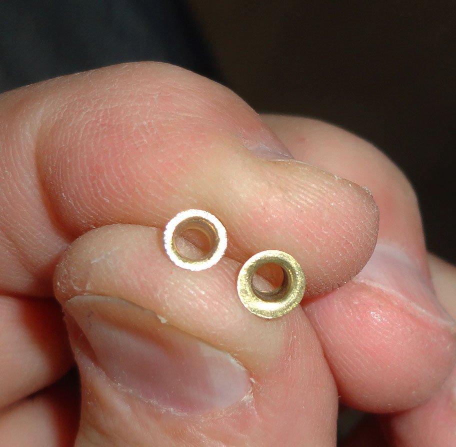
'Might as well make a number of 'spares', as I'm prone to losing things.
- Glen McGuire, Keith Black, davyboy and 3 others
-
6


Mayflower by Ferrus Manus - FINISHED - Heller - 1/64 - A ship for my Uncle Jay
in - Kit build logs for subjects built from 1501 - 1750
Posted
Point well taken, so I consider it being optimistic on how many years of retirement there will be to enjoy before disabilities of one sort or another hamper me too much. Besides, 4 in the stash are plastic kits obtained for comparison and study e.g., the Lindbergh/Pyro R. E. Lee (plastic) is identical in scale to the classic Scientific R.E. Lee (wood based) aprox. 1:163 ... and there are many plastic parts from the Lindbergh kit that will enhance the detail (and ease of build) of the Scientific kit - a 'melding' of the two as noted in another MSW thread. I've reviewed all the Lee builds on the forum and look forward to my own in the future (assuming I don't check out beforehand).
One considered in the stash is actually underway (suspended build of the 1970s Sergal Great Harry). The sheer size of the aprox 1:65 original kit, and also the inaccuracies in design due to the lack of information then (the Mary Rose had yet to be discovered, raised and preserved), prompted me to re-scale and correct all the bulkheads at 1:88 (cutting them all from new flat stock).
After completing the restoration of the Gorch Fock - getting some practice at rigging in the process, it will be back to finish the Vasa to the extent I've decided on, and then a return to the Harry - a very interesting project indeed. That will leave the Billings Oseberg & Roar Ede (both 1:25 - a nice pair), Occre Endurance (about 1:70) the R.E.Lee and a perhaps version of the Golden Hind based on my research - but that might be left to someone else.