Thukydides
-
Posts
1,362 -
Joined
-
Last visited
Content Type
Profiles
Forums
Gallery
Events
Everything posted by Thukydides
-
 Fantastic job. I have enjoyed following along and watching your research processes. You should be proud of your work.
- 312 replies
-
- 4
-

-

-
- Chile
- Latin America
- (and 6 more)
-
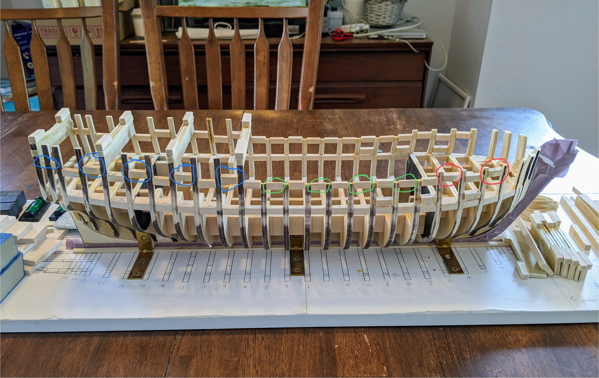
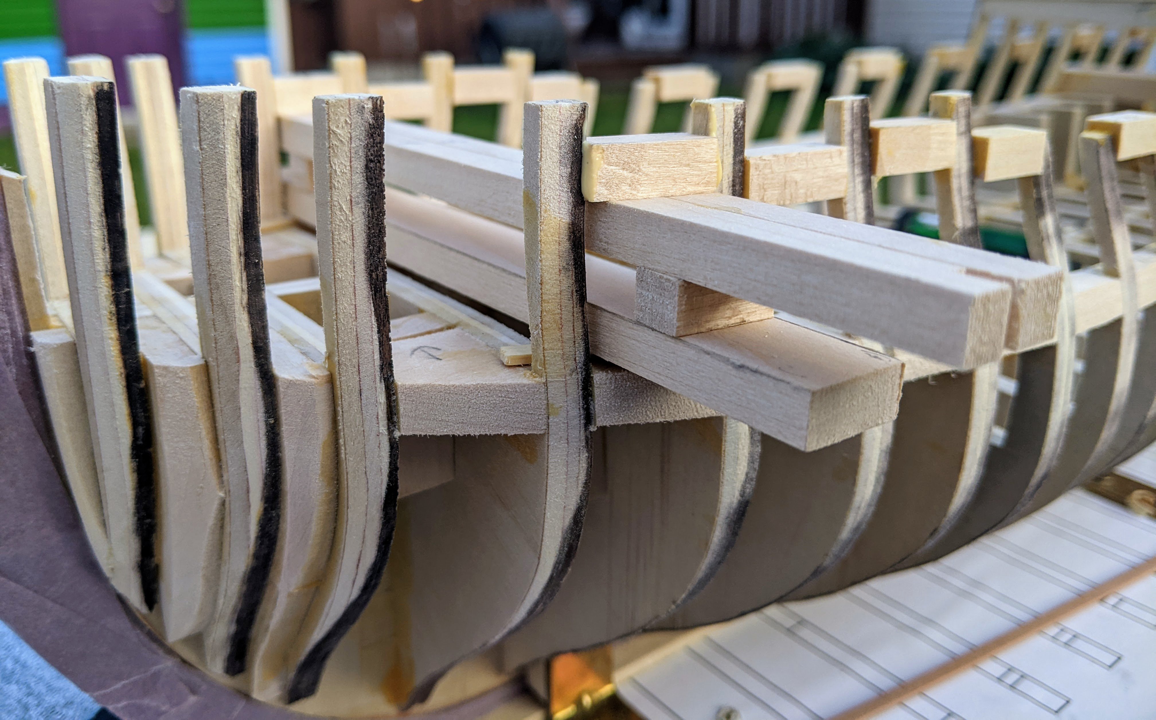
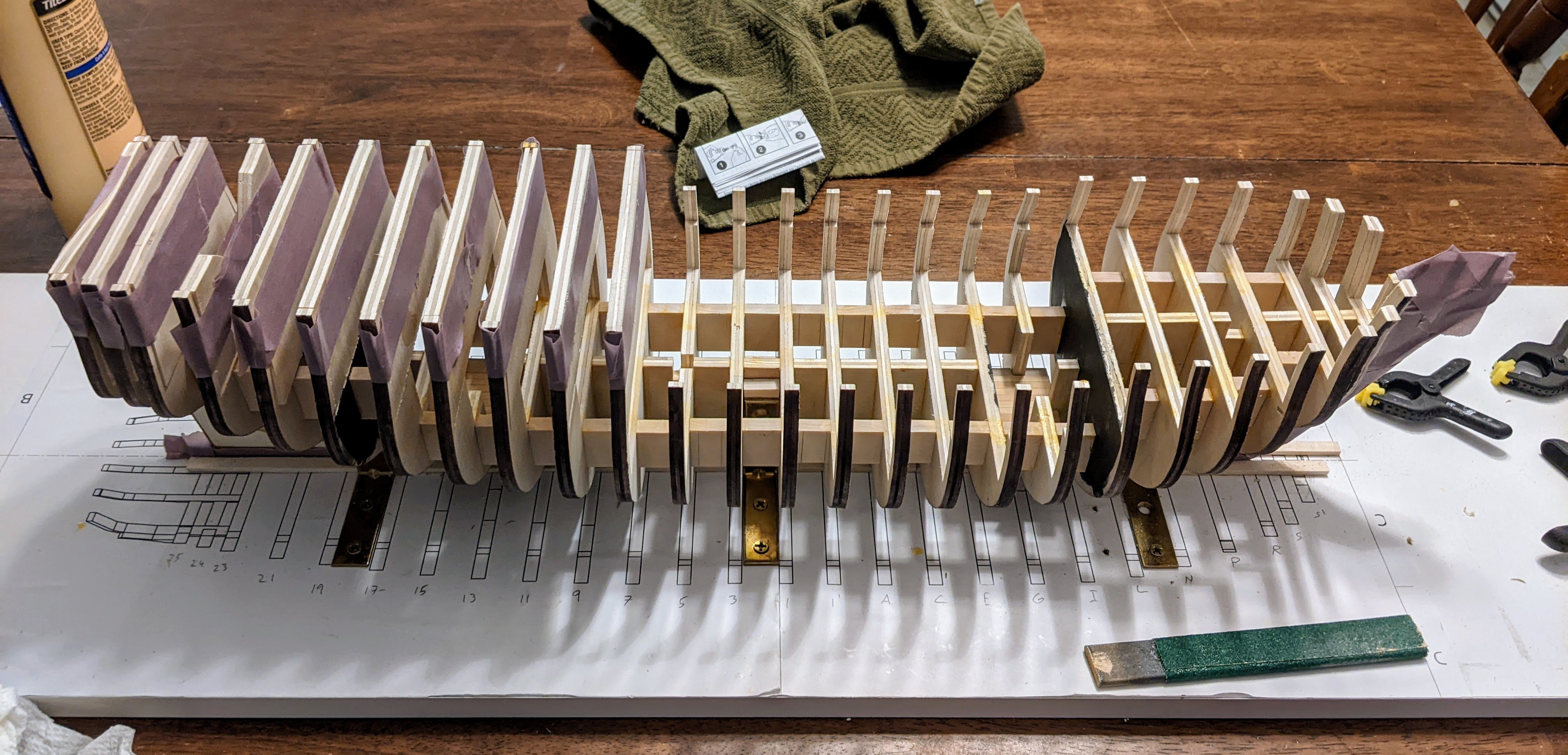
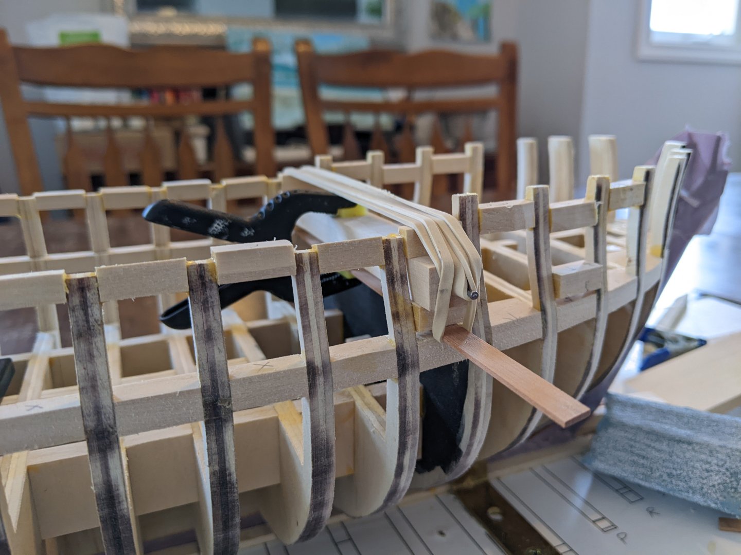
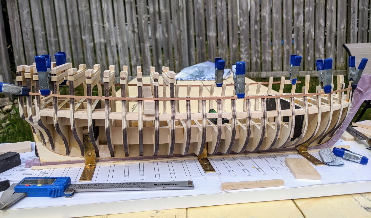
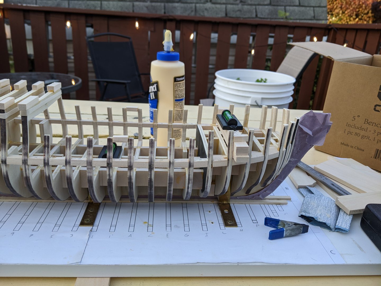
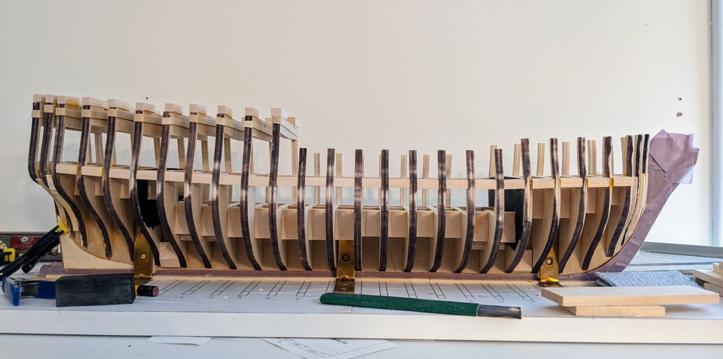
Log #26: Framing the Gun Ports Part I I have started work on one of the more consequential parts of the structure of Perseus, the gun ports. These represent one of the one of the visual focuses of the model. The line of the gun ports catches your eye so getting the sweep of them right is important to making the model look right. As I mentioned in my last post I have been working on getting the inboard sweep of the deck right and that was my starting point for measuring the ports. Given the size of the basswood I was using for the framing (1/4 inch), there would not be much space below the lower port so I decided to start with the top of the ports. Starting in the middle of the ship, I used a jig to measure a consistent height. The jig is built from 3 layers. First on each side I had a small strip of wood which was used to line things up with the sheer of the deck at that point. On top of these were some folded paper (as this was the easiest way to add consistent small amounts of thickness to get the height right) followed by a spacer piece 1/4 in thick. Above this was a piece of wood the exact height of the ports. This also allowed me to check using a level that the ports were the same height on both the starboard and larboard sides of the ship. I then glued the upper port frames to the bulkheads using the jig to position them at the right angle and height. I did one of the middle ports and the ones at each end before using a batton to check how things looked. Every time I did another port I would check how it fitted with the batton and adjust the inboard profile of the deck as necessary. At this time I also placed cross bracing pieces between the bulkheads at the height of the forcastle and quarterdeck beams. For the forecastle I used spacer jigs (similar to the ports), but for the quarterdeck I had to be a bit more creative as according to the contract, the fore end is a different height than the aft end. So I measure and marked the two ends and then used battons to make a smooth sweep. This is not as important to get perfect as these heihts can easily be adjusted later and the main point of these bracing pieces is to strengthen the structure in the space between bulkheads that don’t have ports. You can see below a picture of the jig used for the quarterdeck. For the lower pots I used my jig for the port heights held up by a rubber band. I then used an old piece of scrap wood to apply pressure to the bottom of the port framing to hold it against the bottom of the jig at the correct height and angle. And this brings us to where things currently stand. I am still working on the lower framing for the ports, but the strengthening structure has allowed me to remove some of the bracing pieces I had in place. The top of the quarterdeck beams follow the line of the top of the pieces circled in blue, the forecastle the ones circled in red and the green ones are just extra pieces I added to strengthen the structure. You can see that I have 3 of the ports framed (though I still need to add vertical pieces to set the width). I also still need to prepare the framing of the foremost port, but that will first require some more faring as it is on the curve of the bow. Thanks to everyone for all your encouragement.


-
I only did this after it was on the model. This was mostly to remove the shine of the poly rope and any super glue that was visible, but also helped protect and hold everything in place. If you do it earlier then you can make white bits of varnish flake off as you are manipulating it (not a good look). If you are looking at my log then look at my later rigging work as opposed to the earlier stuff. I got a lot better as I went along and found better ways to do things.
-
Good to see you back at it. Serving is a bit tricky. It takes time to figure out the twist and the tension. I found mechanically fastening the ends as well as glue helped. I would use a needle to run the serving thread through the rope being served with a very small bit of super glue on that part to hold it there. Also I found that magnification helps a lot. If you are looking for ideas you can check out my alert log. I discuss much of this in detail there.
-
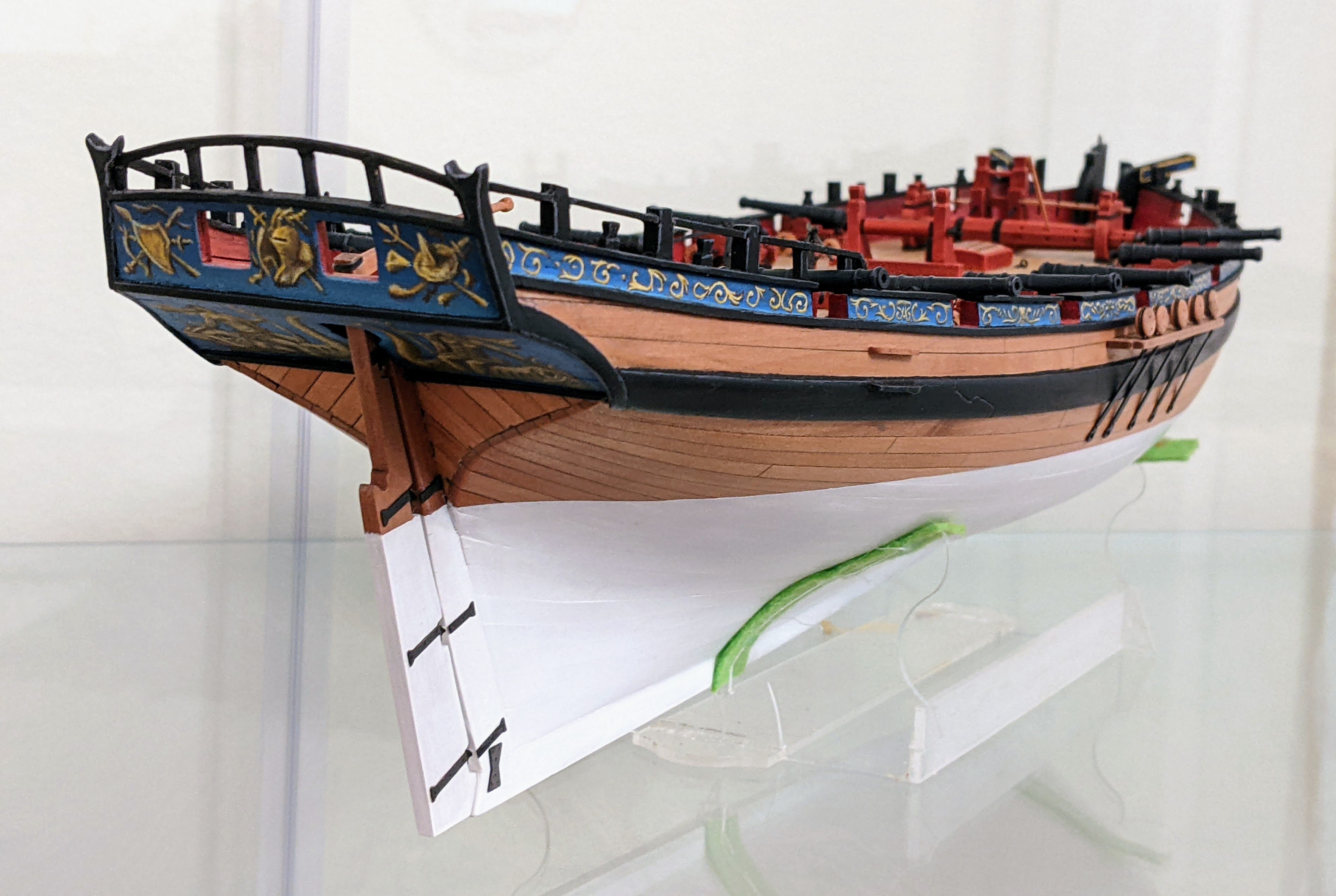
Looking good. The stern area is a bit of a funny one with a lot of inconsistencies between the Marshall painting, the plans and the Goodwin book. I ended up redoing mine after the fact. If you are feeling really adventurous you could try painting the counter and transom as per the Marshall painting of Alert.
-
I am just noticing that you started a new build and it is looking great. The boxwood planking of the lower deck was a great decision.
-
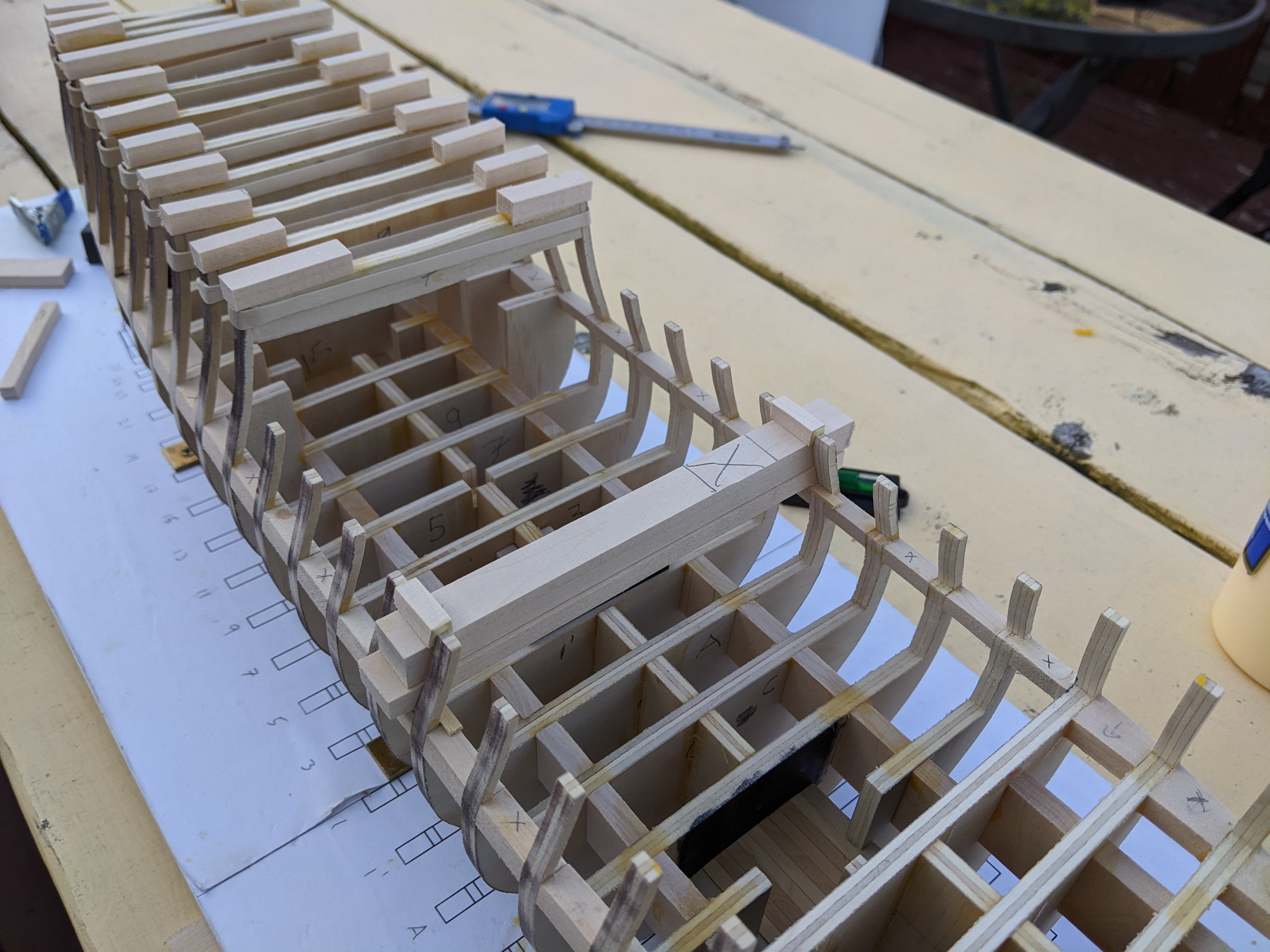
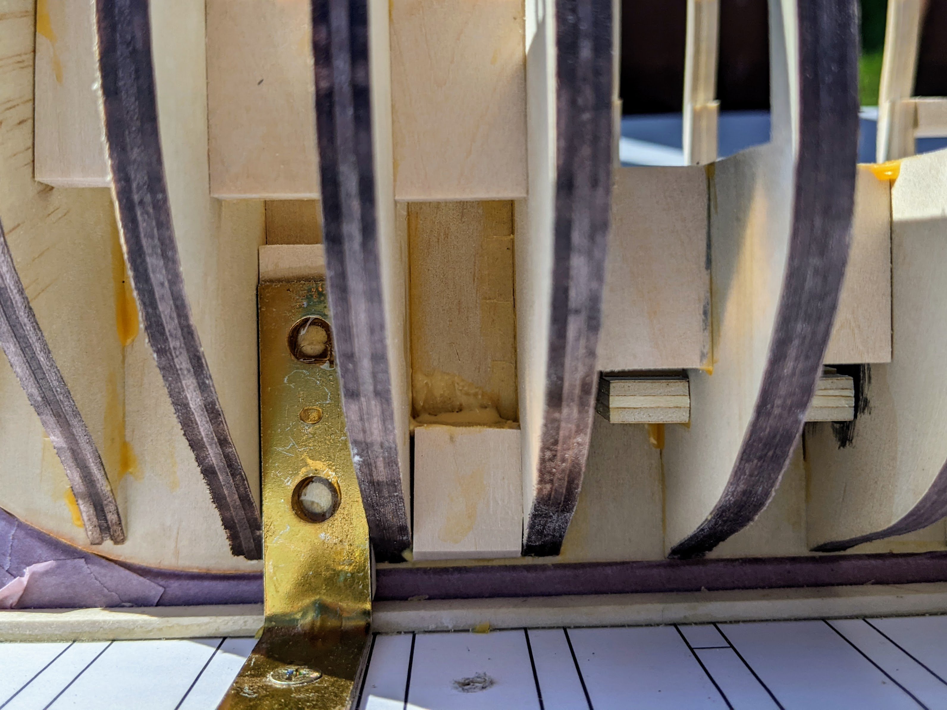
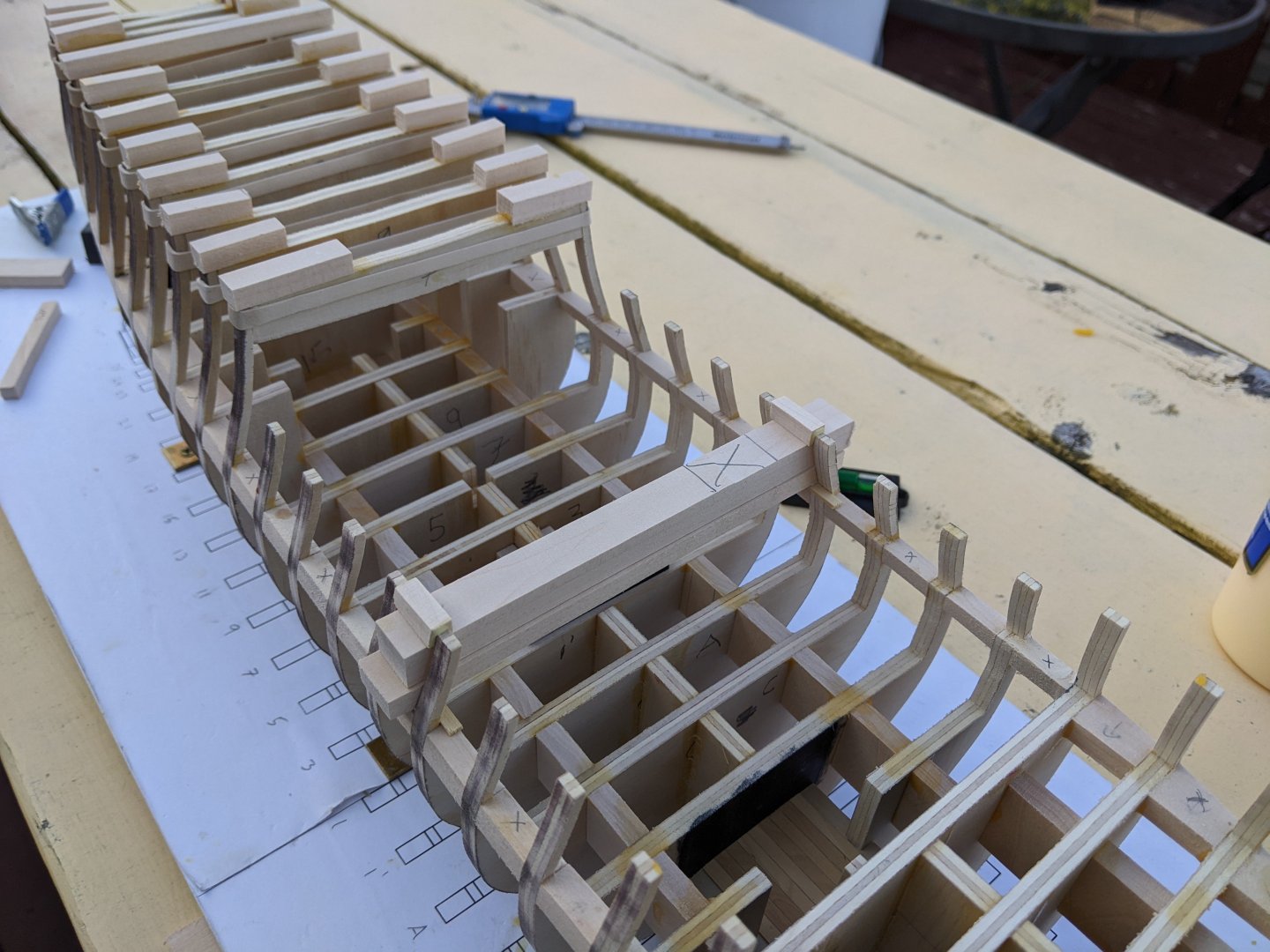
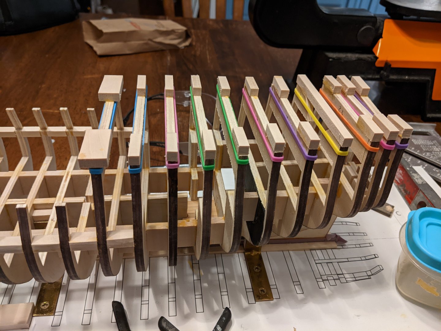
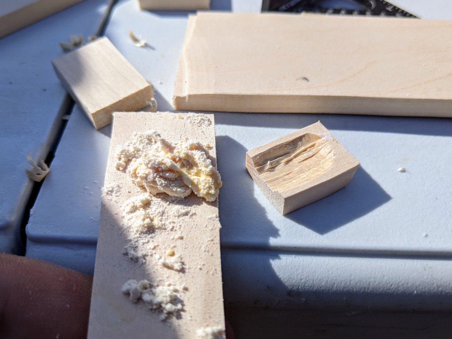
Log #25: More Structural Supports and the Deck Sheer It has been almost a month since I last posted as I have been busy with other tasks and though work has progressed, there had not been a lot of significant progress. One challenge is this work generates a lot of dust and so I have been trying to do it outside (I don’t have a dedicated workshop space). Between rain and the fact that most of my free hobby time is in the evening, this has slowed the process down a bit. Along the way I realized that the existing inserts I had taped in place to support the thinner bulkhead extensions were in the way and so I cut off the bottom of them and added glued pieces above them to hold them in place. Then I place rubber bands around the whole upper part of each bulkhead to hold it together. This is actually more sturdy than what I previously had done and it also keeps the supports out of the way. I have been doing some preliminary faring as I add the bracing pieces along the sheer of the deck. The bracing pieces are now all in place, though the ones near the bow and stern have not been fared at all yet. As you can see from the below picture, the sheer is not perfect and so now I need to make small adjustments inboard to make sure the line of the deck is right. Then I can use that line to measure the gun port heights. The sheer will also allow me to measure and mark the height of the quarterdeck and forecastle and I will likely add bracing pieces to mark their locations before I start faring in earnest. I have also taken the opportunity to reinforce the area where the nuts are glued to accept the bolts that will attach the model to the base. To do this I cut pieces of basswood and then used my mini chisels to hollow them out. I then filled this hollow with a wood glue sawdust mixture. This was then pressed in place over the area of the nuts until the excess sawdust-glue mixture started to squeeze out indicating the area was fully filled. This is probably overkill, but as it didn’t take much time, I figured it was worth the effort to make sure that these don’t come loose. So that is all I have to show so far. Thanks to everyone who had stopped by to take a look. On the research side of things I don’t have much to report as I have only had time to transcribed a couple letters and they didn’t have any particularly significant info in them. Hopefully the next ones will have some more interesting information.

-
There is also a significant amount of evidence to suggest that the false keel was not coppered (at least with regard to British ships). Also some ships also had the uppermost layer of plates done after the fact running along the waterline to sort of finish off things. It seems that the upper edge of the covering was covered by a wooden batten or possibly canvas, but there is very little said on it and specifics are hard to come by.
-
Great progress jaques. The sails are looking really nice.
- 312 replies
-
- 4
-
-
-
- Chile
- Latin America
- (and 6 more)
-
Looking good. I have also been experimenting with tin foil for the water though in my case I am going to be using it directly on the base. I have found at least so far it really helps in getting a dynamic base working.
-
She is looking really nice. The time and care you are taking is paying dividends.
-
You essentially have two options. 1) You can carefully remove the offending planks and replace them. This is the option I would go with. Note this is the only real option if you are planning on leaving the hull unpainted. If you used super glue to attach the planks then careful use of acetone can help with removal. For wood glue isopropyl works well. 2) you can leave as is, maybe add some more filler just making sure the shape is smooth and right. If you are painting it white then it shouldn't be that noticable. Good luck.
-
They do look really nice. Harpy is also looking good.
- 332 replies
-
- 3
-
-
-
- Harpy
- Vanguard Models
- (and 1 more)
-
Great job Glen, I think you made the right choice. Just a little bit of green adds a nice bit of colour. It is a fantastic model with a great presentation.
- 106 replies
-
- 5
-
-
-
- Kentoshi-Sen
- bottle
- (and 1 more)
-
Congrats on a great build. You have taken the kit and made it your own. I appreciate all the little details you have added.
- 38 replies
-
- 2
-
-
-
- Alert
- Vanguard Models
- (and 1 more)
-
Thanks Jacques, Oh it was expensive, in many cases it cost almost as much as it cost to build the ship in the first place. For example Perseus was built by contract for a cost of £4,507, but her coppering cost £4,310. That said there were certainly some significant benefits. Many of the refits that you see documented often cost 50% of the ships original cost to complete. One document I have just finished transcribing is an analysis of the impact of coppering and he has this to say:
-
Log #24: Structural Supports & Fixing Mistakes Thanks to everyone who has stopped by to take a look at the log. I do find your comments and likes motivate me to keep pushing forward. Since my last log entry I have continued to work on the structure of the model. I will discuss that in more detail below, but I have also in the background been continuing my work on research. My current focus is on the coppering of Perseus. She was one of the first ships in the RN to be coppered and though I am not planning on coppering her, I am planning some aesthetic choices which will allude to the coppering. The handwriting of the documents I am currently looking at is not as good as some of the stuff I have previously looked at so it is slow going with the transcriptions at the moment. But I thought I would share an interesting tidbit I found. It is interesting to see how quickly the RN went from very few ships coppered to coppering a huge share of the fleet. You can see in the above transcription that from 1779 to 1781, 313 vessels were coppered. On the model itself, I have now got all the bulkheads in place. You will notice that the front two and stern two bulkheads do not have any bracing pieces as they are closer together. The reason for the omission is that I am planning on filling in these sections fully with filler blocks. First I cut the bow filler pieces and glued them in place. Then once that was dry I slid pieces of basswood which I had thinned to the appropriate thickness into the gaps between the bulkheads and marked off with pencil the approximate size they needed to be before cutting them out on the scroll saw. There is no need to be particularly accurate here so I have erred on making them oversized as this will all be sanded in the faring process. The most important part of this was making sure the bulkheads remained square through this process. However, it was around this point that I realized I had made a mistake with one of the bulkheads. Essentially the slot was not deep enough and so it was not far down enough on the center bulkhead. It was only off by about a mm, but this is enough to throw off the lines of the ship. So I had to break out the isopropyl and slowly work it free with a knives and solvent. It was particularly unfortunate that the offending bulkhead was at just about the worst possible location (the stern platform also had to be removed). However after a few hours of working slowly and carefully on it, I managed to get it out. Then I sanded and dry fitted it back in place, making extra sure of the positioning this time :). Finally, I have also been starting the outer structural supports. This is a line of bracing pieces which run along the upper deck line. These serve three purposes: To allow me to correct for any warped bulkheads which might be square at the base, but are not square at the upper deck bulwarks. To strengthen the overall structure. To allow me to better see the line of the main deck to determine if I need to make any adjustments. These pieces are inserted square to the bulkheads, but at an angle such that they follow the sheer of the deck. I will then use a combination of planes and sanding to trim them back in line with the frames. Getting the sheer of the main deck right is crucial as it will determine the height of the gun ports. It feels like this structural work is taking a really long time, but I am trying to avoid future problems by making sure I am constantly checking to make sure everything looks good now while it is easier to fix.


-
I think that looks much better than your previous versions. Great jobQ If you would like some suggestions to make it really pop, I would still go up a little higher in value on the highest highlights of the red. Maybe mix a bit of orange in with your red to get that highest highlight. On the gold I would use pure white or maybe white with a little yellow in it and try and pick out the upper edges of the monogram and any sharp upper edge points such as the tips of the cannons. This would be really small dots/lines, but it will push that contrast just that bit higher.
- 125 replies
-
- 4
-
-
- Christiania
- Vanguard Models
- (and 1 more)
-
I agree with the others that the second is probably the better option. What I would suggest is there is a bit too much of a hard transition from the bonsai to the rock. To alleviate this you could add some moss around the base of the bonsai to allow for a transition to the rock. Not much, just a little to make it less of a hard line between the two.
- 106 replies
-
- 5
-
-
-
- Kentoshi-Sen
- bottle
- (and 1 more)
-
Great job on the anchor. It does look like rusty metal.
- 312 replies
-
- 3
-
-
-
- Chile
- Latin America
- (and 6 more)