
Thukydides
-
Posts
1,369 -
Joined
-
Last visited
Content Type
Profiles
Forums
Gallery
Events
Everything posted by Thukydides
-
 Congrats and great job.
 -
There is only the catalog entry: https://discovery.nationalarchives.gov.uk/details/r/C13422581
-
An interesting corollary of the 1782 letter is that it suggests that prior to that date the coppering was often done over the false keel.
-
As @Desertanimal said I think the rope looks a bit big. With 3pdr guns she would use a 3 1/2 in cir breaching and a 1 1/2 in cir tackle with 5in blocks. At this scale that works out to 0.44mm and 0.2mm diameter rope for the breeching and tackles respectively 2mm blocks would be appropriate. Rigging at this scale is a very fiddly process and I recommend using magnification as trying to do it with naked eyes is not easy. If you want to be correct to the scale you will need to use something like 10/0 fly tying thread for the seizing. If you don't want to mess with that, then I would recommend skipping the tackle and just going with the breeching ropes. Many choose to do this anyways and it is better to have no tackles then to have ones that are not at the right scale.
-
Great find. Thanks for sharing. I remember there was a thread a little while back discussing this very question, but there was no definitive answer. @Sizzolo you might be interested in this.
-
Looking good. That is a lot of plates :).
-
Now this is much earlier than your time period, but according to the Art of Rigging in 1806, strapping of 4 in diameter and above are wormed parceled and served and less than that just served. They discuss how the serving is done on shore and the lengths just cut off as needed. It is not clear if the splice to join the two ends of the strop (which they state is in the **** of the block :)) was then served over, but I would guess not. p44: https://books.google.ca/books?id=Cq1WAAAAcAAJ&printsec=frontcover&source=gbs_ge_summary_r&cad=0#v=onepage&q&f=false I am not sure exactly what you are asking here, but in general I would expect that the lower down and more permanent the block, the more likely it is to be directly attached to the structure / eyebolt. The higher up and less permanent it is the more likely it is to use a lashing to attach two ends of a loop or to use hooks. I don’t have any sources for this assertion, just what I have observed the tendency in the examples I have seen and logic (I would assume that it was much harder to do this on the top of the mast as opposed to on deck). The mast is looking good. Nice job on the fix.
- 312 replies
-
- 4
-

-

-
- Chile
- Latin America
- (and 6 more)
-
Yes it was the actual cement residue that was the problem. I will remember this for next time. I just used a course dish cloth and it all came off, just it took a while.
-
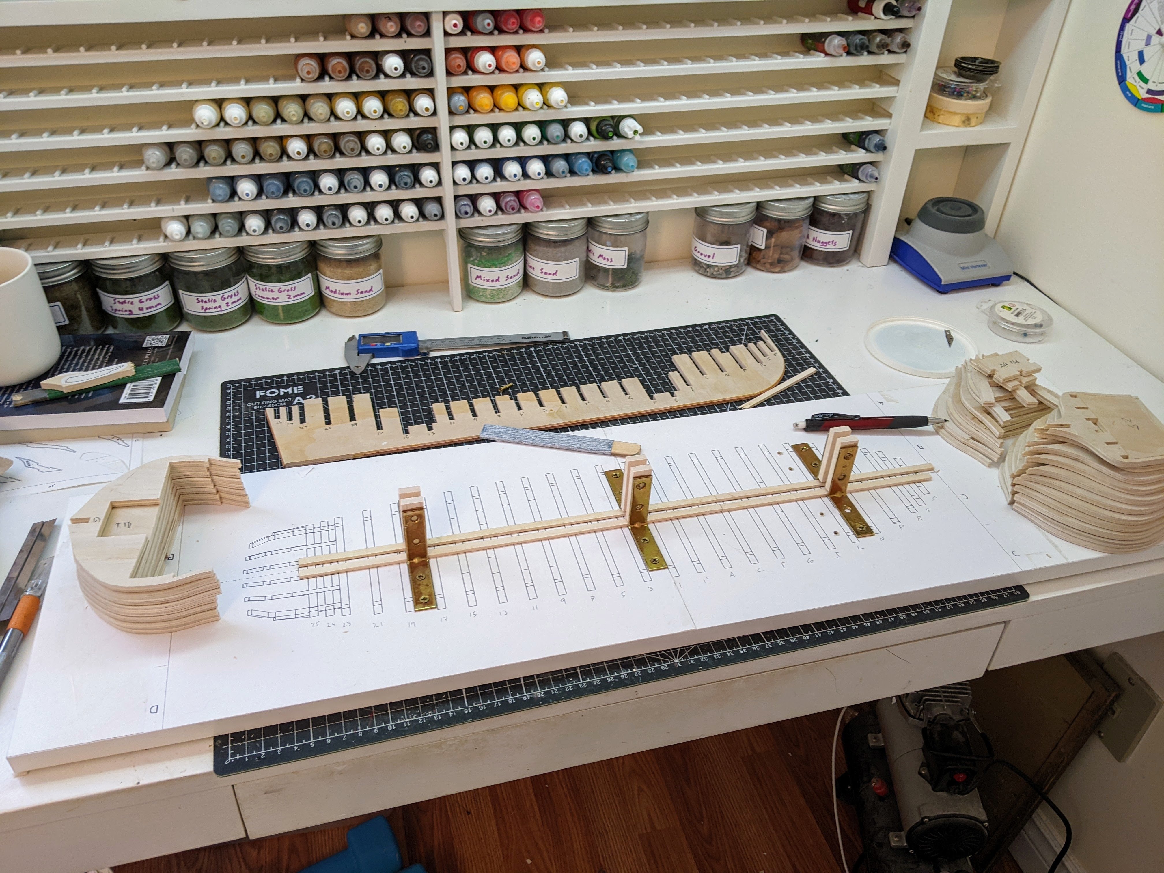
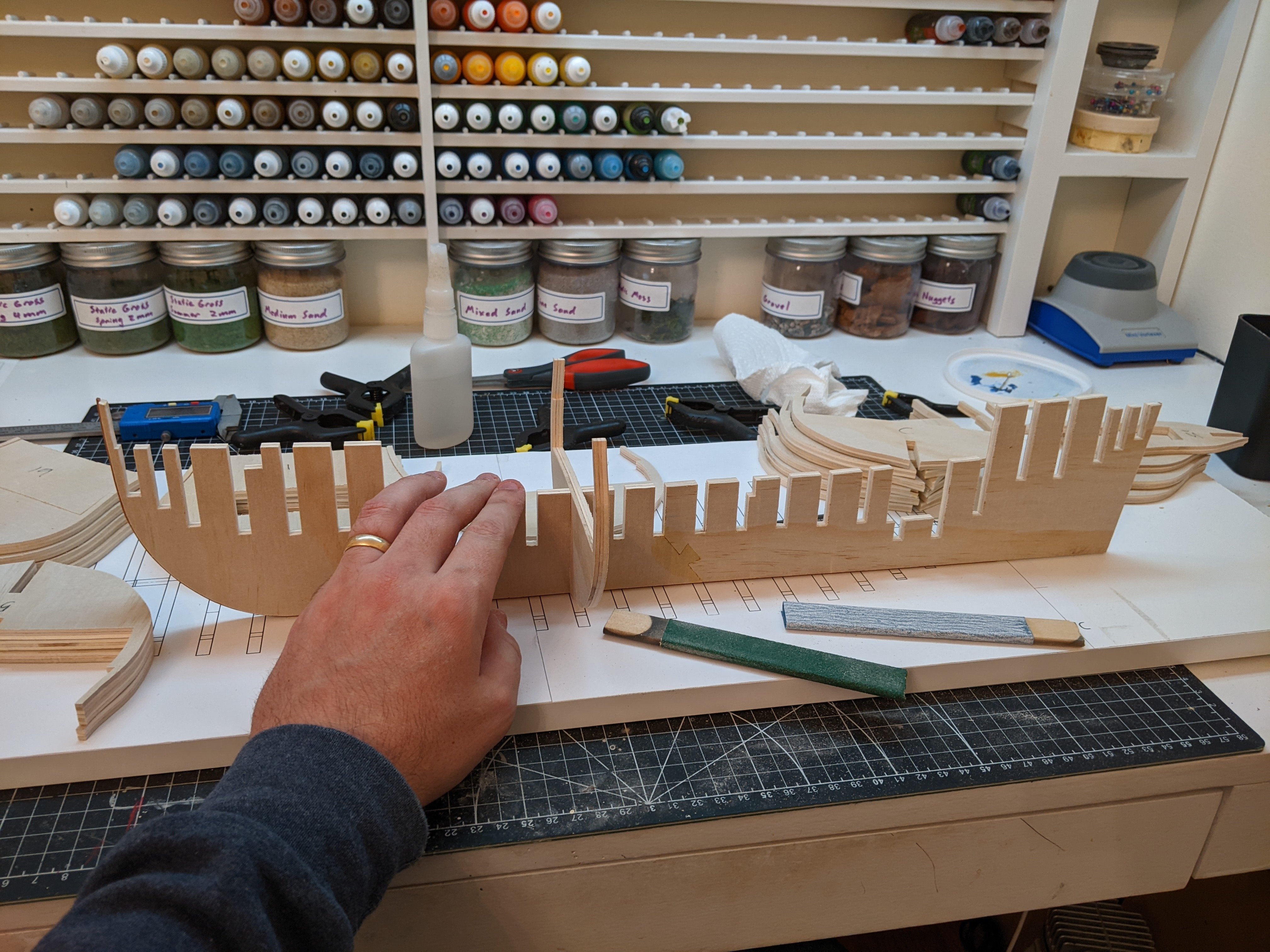
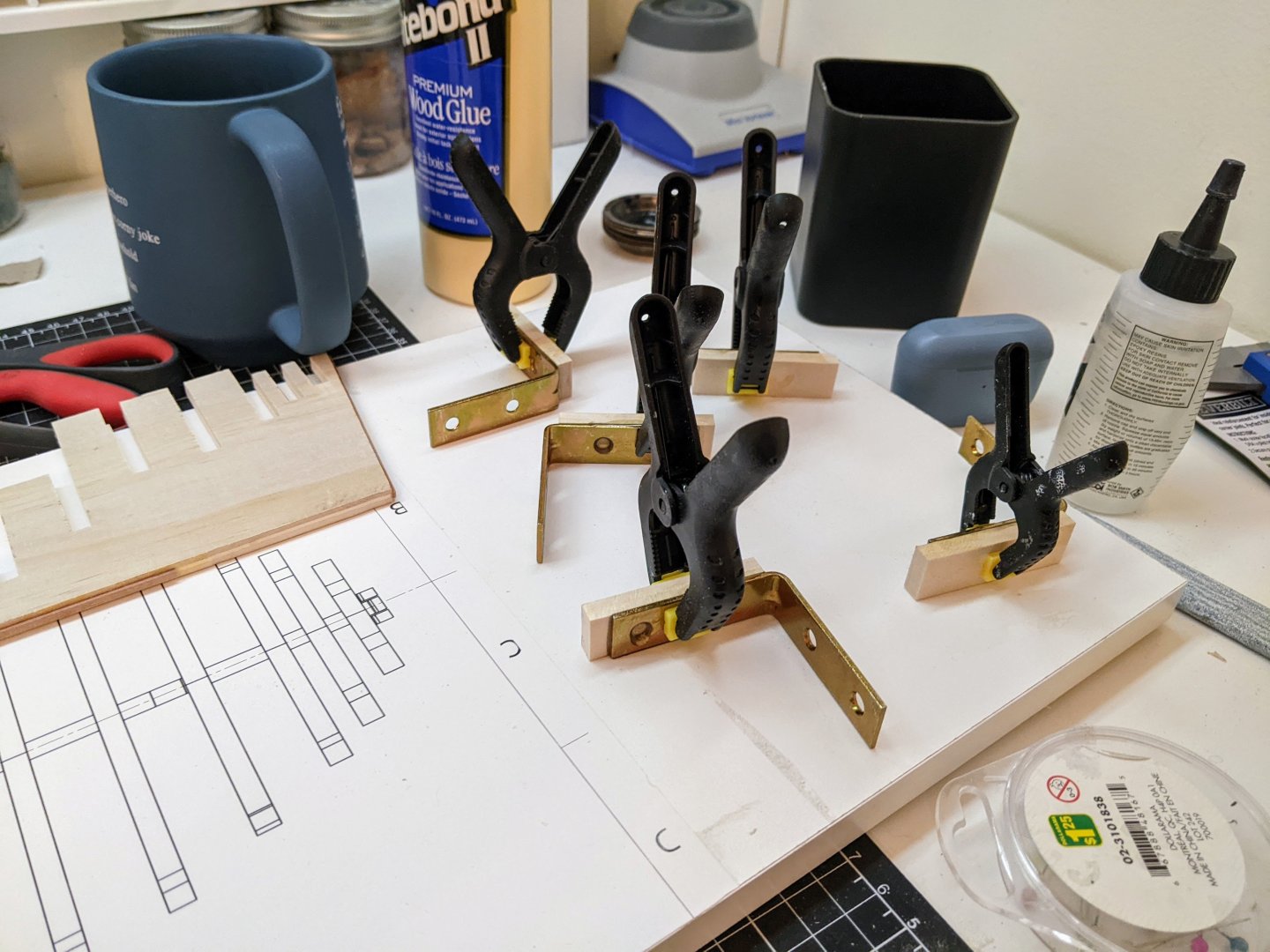
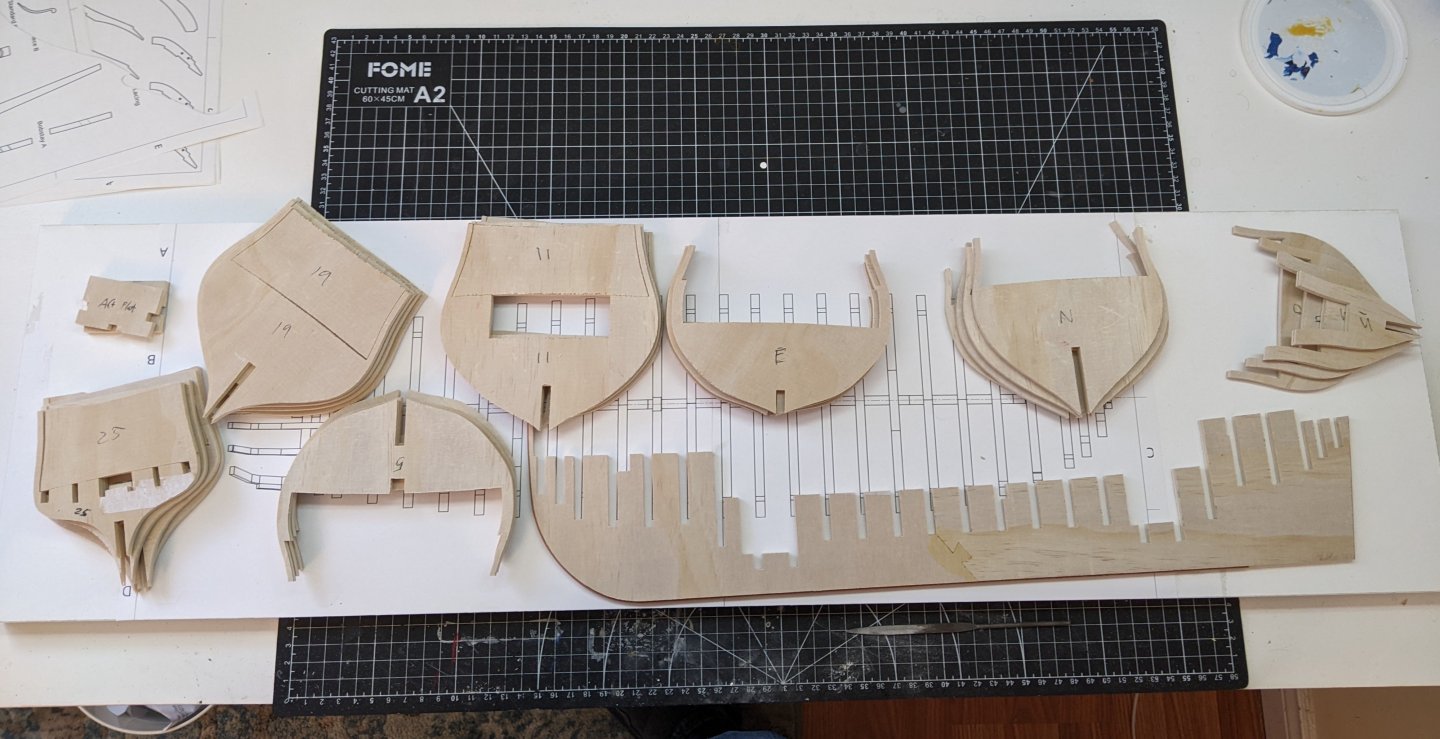
Log #16: The Build Board & Dry Fitting I have finally finished cutting the all the bulkheads. I then had to remove the templates and rub off the rubber cement residue on them. This was actually one of those things which took a surprising amount of time to do. Then came the rather lengthy process of checking the fit of all the pieces. I want them to be snug, but not too snug such that they exert too much pressure and cause things to warp. Also I need enough play to allow me to make small adjustments to make sure everything is square when it comes time to start gluing. I made some sanding sticks to help with the process and as luck would have it, the course one was just the right thickness such that if I could get it into the slots easily they were sized correctly with only minor adjustments with files and the finer grit stick. Then it was time to make some brackets to hold the centre bulkhead straight while I am constructing the bulkheads to ensure there is no twisting till all my reinforcing pieces are in place. I just used off the shelf corner brackets and glued a piece of wood to them to allow them to reach over the keel clamp that runs along the build board. And here below you can see the current status of affairs. Everything is now ready to start building, I just need to have enough confidence to start cutting the wood for the stem/knee of the head/keel. I also need to finalize how I am going to ultimately secure the ship to the base as the hardware for that will also need to be added to the centre bulkheads prior to the structure being built. @JacquesCousteau Yes I also agree with you. It is mostly a matter of getting a tight joint. The tighter the joint, the less gap there is to be filled by the glue-paint mix and so the less visible the lines are. My goal with all of the planking etc. is to have the major structural joints only somewhat visible from 6 ft away and all the minor ones (such as the planking) to be invisible. But then when you get closer all of them can be seen. We will see how well I manage to achieve this, but that is the goal. I am still undecided on what to do with bolt joints as convention is often to have them very visible, but in real practice they were covered with wooden plugs so would not have been that visible. Similarly I have not yet figured out what I want to do with the horseshoe and fish plates. As far as my reading has gone they appear to have been made of copper, but black is a much nicer colour to show them off. So many decisions and we are getting closer to the point where I can’t put them off much longer… Thanks for stopping by.


-
Looking good. If I may, I would recommend rigging the breeching ropes off of the guns. It makes it much easier. See this post for an example of what I mean.
-
Those cannons look great. Well done! Also good job on the steps. Not adding them is one of my regrets with my Alert.
- 38 replies
-
- 2
-
-
-
- Alert
- Vanguard Models
- (and 1 more)
-
Fantastic! I like how your designs are giving more and more options for opening up more of the ship.
-
Fantastic work. You should be proud of her. That is a very impressive display. Three lovely ships.
- 422 replies
-
- 1
-
-
- Vanguard Models
- Sphinx
- (and 1 more)
-
Great job, the fittings are looking really good. How did you make the hinges or did you buy them from somewhere?
- 38 replies
-
- 1
-
-
- Alert
- Vanguard Models
- (and 1 more)
-
What I did was get a piece of paper and mark the curve by pushing my pen into the rabbet. You can see more on it on my alert log here: https://modelshipworld.com/topic/29520-hm-cutter-alert-by-thukydides-finished-vanguard-models-164-first-build/page/2/#findComment-857441
-
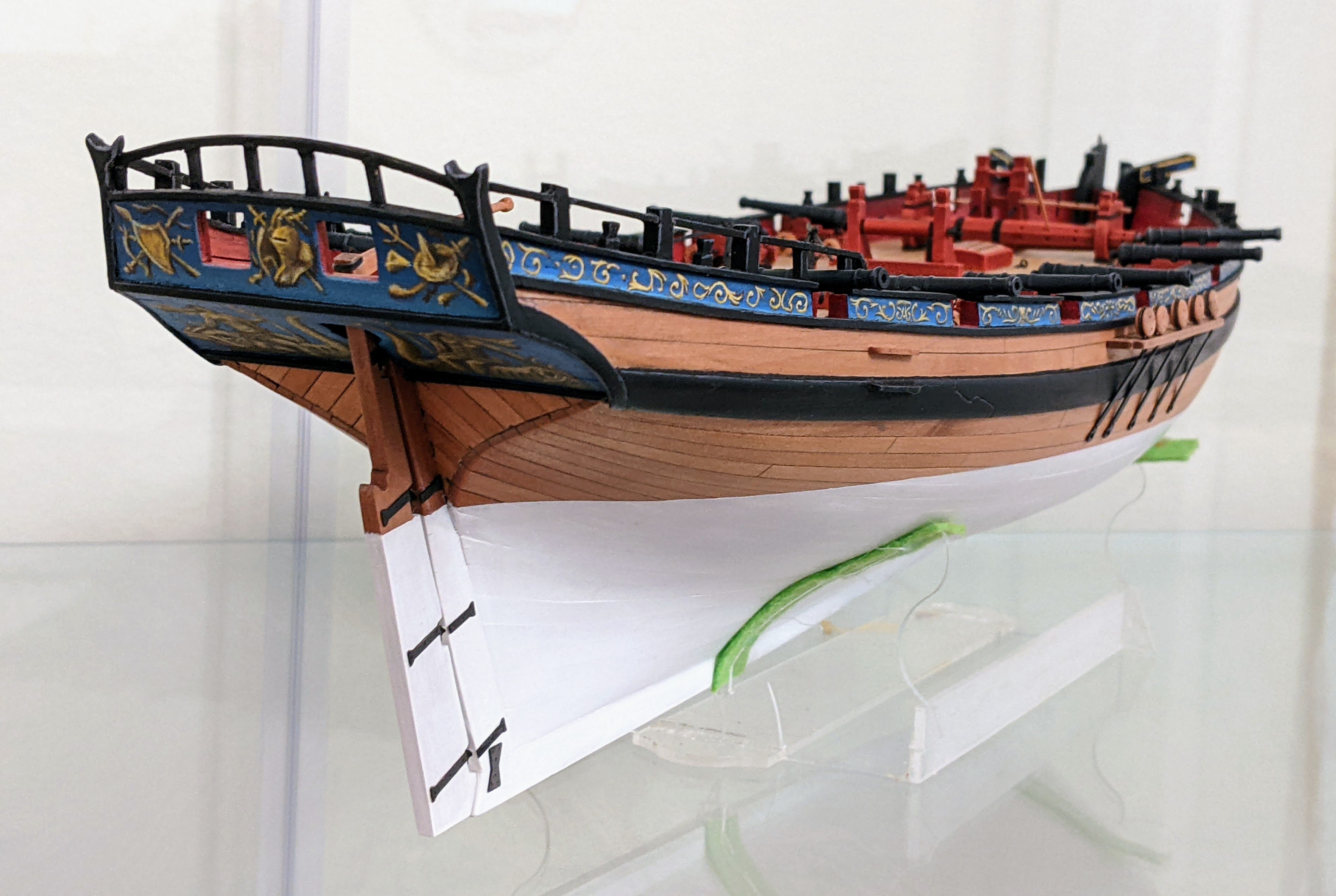
I use my airbrush to apply the primer (though going forward I am thinking I may also use it for the deck as getting into some of the corners was a little difficult. Apart from that it is just normal paint brushes. I use a size 1 round for most things and then drop down to a 0 or double 00 as necessary. But I would say 90% of the painting is done with the size 1. I follow my normal process I documented on my alert log of starting with a darker base tone and then layering in highlights. The key is to keep your paint thinn and not flood the model so you don't hide the detail. Many thinn layers is the way to go. In some ways these small ships are very forgiving because people can't really see how your errors. The goal is to give the illusion of accuracy not actually to achieve it. For example is you zoom in really close on the scroll work on the cutter it is just blobs of yellow.
- 39 replies
-
- 2
-
-
- Black Seas
- wargaming
- (and 1 more)
-
New to ship modelling? But what do you build first?
Thukydides replied to MSW's topic in Wood ship model kits
As you say you need to have an interest in the subject matter, but I would caution you about doing a 3 master. The Rigging is a whole skillset in and of itself so even if you are comfortable with the woodworking side of things, you my find yourself bogged down on the rigging with such a large project. My view of the matter is that you don't know what you don't know until you do it and I chose to do something a bit smaller first to make mistakes on before trying "the ship of my dreams" so to speak. That being said this is not to say you can't be successful diving right in, just that I would recommend starting with a smaller project such as a cutter or maybe a small brig first. -
I have never used MM acrylic, but I have used many other brands. There is no need for a special thinner, just use water. Now if you are watering it down really far so it is more of a glaze, then sometimes you need to add in some glazing medium or similar. In most cases I just put the paint on my wet pallet and then press into the pallet until the paint is wet enough for me. In general the consistency you are looking for if just doing normal layering is such that when you paint a bit on your palm you can still see the lines. When thinning for use in an airbrush then yes I use a mix of isopropyl, water, flow aid and airbrush thinner, but that is because you are trying to avoid the paint drying in the airbrush and clogging it.
-
@TJM Thanks, they are kind of fun. However, I currently am not making much progress as I am exploring the possibility of making them even smaller :). The reason is I am not entirely happy with the black seas rules and how small the table feels. Age of sail should be mostly about the maneuvering before battle not the battle itself. So I have been exploring other rulesets and also doing some small tests trying to make up a ruleset of my own. As part of this I am experimenting with going down to 1/1200 scale. I am waiting on my friend to print me off some test versions of the brigs to see how viable it is to model them at that scale. Obviously there will be less detail, no crew etc, but the question I have is can I make them look good enough that I am happy with them. We will see how it turns out and I will document my tests here. The tricky part will be getting enough rigging in place and having enough differentiation in mast / yard thicknesses. One question is how to do the shrouds, I was thinking that I might try using actual thread as at that scale the ratlines would probably not be visible in real life anyways. The advantage of this would be I have a lot more control over the position of the shrouds. Going smaller sometimes makes some things easier as people can't actually see the things you left out. @Toolmaker You are correct, it did occur to me that this was probably the best solution but that would require me to have soldering tools which are an expense I can't justify at this point. In the end I found a few things helped. I cut notches in both the yards and masts to help the glue grab. After painting I did simulated slings with thread to hold them in place. These actually did a pretty good job. Finally, I found that the sails, once stiffened with mod podge (and super glue on the edges) and then varnished when in place actually made the whole thing pretty durable. In addition like on an actual ship, once the rigging is in place it helps balance everything. In the end the final products were very durable. I could probably drop them on the floor and they would be fine (not that I tried). They certainly were strong enough to take some rough handling.
- 39 replies
-
- 4
-
-
- Black Seas
- wargaming
- (and 1 more)
-
It is more as @AON said that carronades were not considered guns. I ship had a rating corresponding to the number of long guns it was armed with, there are examples of ships being given extra long guns on the quarterdeck and then being rerated from a 20 gun ship to a 24 gun ship. Carronades were not included in this number except in a few unique cases (such as the Rainbow) where the carronades replaced the entire armament. @AON covered the history very well. The only thing I would add is that there are 1782 and 1793 lists that respectively list the actual carronade armament of ships in the RN at the time. However that is well before the time period of the battle of the Nile. I do have a list from 1802 which suggests the official armament for 74s was 2 32 pdr caronades and 6 18 pdr ones, but it doesn't indicate where on the ship they were. Proportion of Carronade Stores Selected Entries Source: TNA ADM 160/150 Date: Circa 1802 A proportion of carronades and stores for a ship of each class in the Royal Navy 100 90 80 74 64 50 44 38 36 32 28 24 20 Sloops Brigs Cutters Carronades 68pdr 42 32 2 2 2 2 8 8 24 6 2 6 6 6 18 6 6 6 6 8 8 12 6 8 8 6 4 Elevation Screws 32pdr 2 2 2 2 8 8 24 6 6 6 6 2 6 6 6 18 6 6 6 6 8 8 12 6 8 8 6 4 Traversing Bars 8 8 8 8 8 12 8 8 8 6 6 8 8 8 6 4 Breechings 7in 4 4 6½ 12 5½ 12 Tackles Complete 2½in 6 6 2 18 1½ 18
-
Welcome to MSW
-
FaceBook miniature tools ads
Thukydides replied to jmlyle's topic in Modeling tools and Workshop Equipment
You were the inspiration for my setup 😄. -
FaceBook miniature tools ads
Thukydides replied to jmlyle's topic in Modeling tools and Workshop Equipment
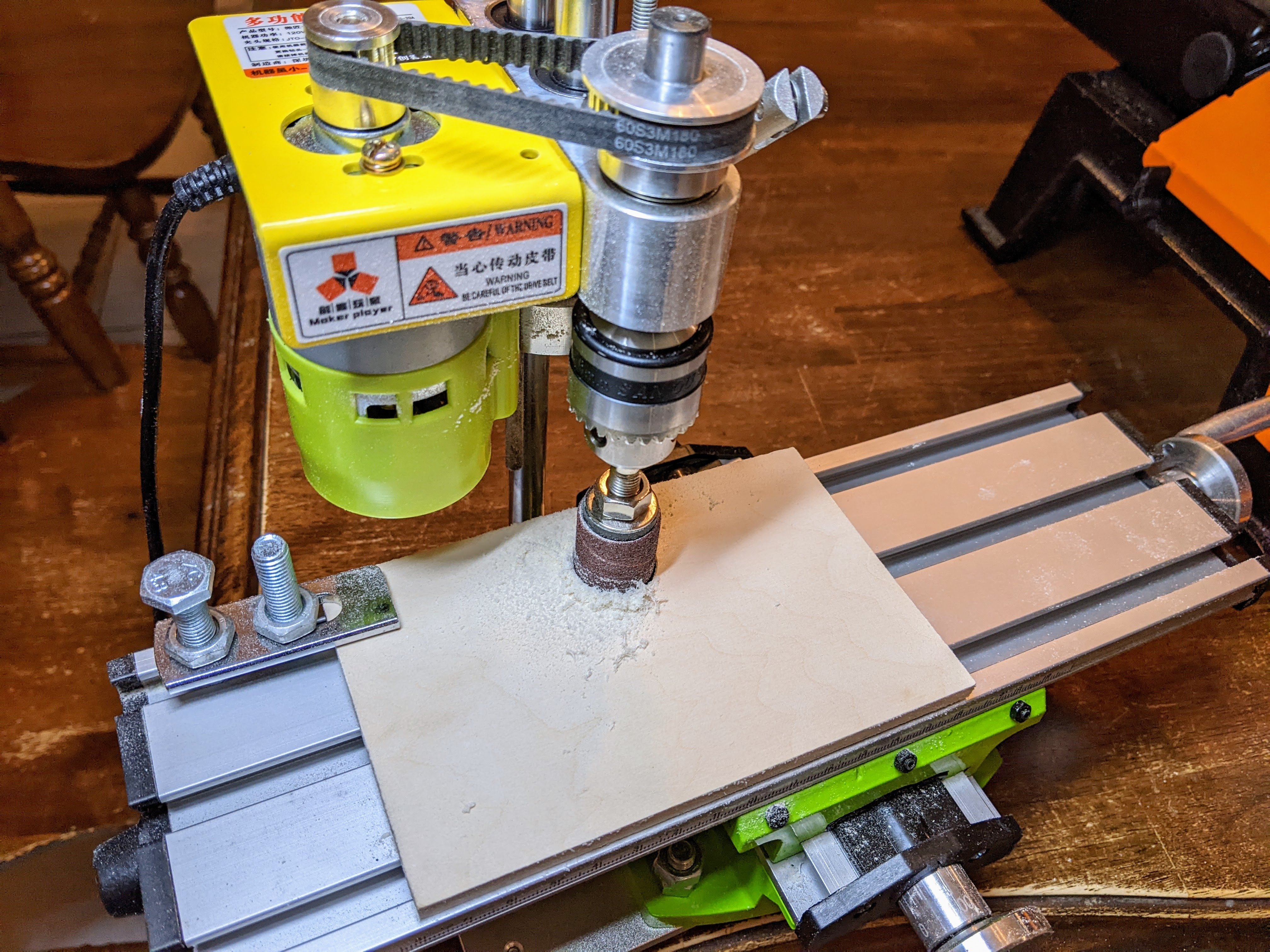
I have a version of that drill press which I got from Amazon. It looks a little different, but many of the parts used to make it are the same. So far it has worked great for me. The only issue I had was the height was insufficient to fit a mini x-y table under it, but that was easily rectified by buying a slightly longer stainless steel rod.
-
Good to see you back at it. I like the stair jig.
-
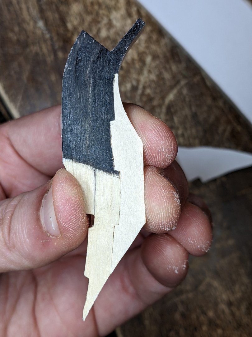
Thank you to everyone for all the encouragement. I figured I would give a small update as work continues in the background with more test pieces. I am starting to get better with the scroll saw so only minor cleaning up with the drum sander is now necessary. I also continue to do more test joint for the knee of the head. With the below example I think I am finally starting to get close to a satisfactory result. This is test article #5 and hopefully the next knee of the head I show you will be the final thing. You can see I also have been experimenting with managing the transition from painted area to unpainted area. The painted areas need white joints to shine through the black paint, but the unpainted areas need the dark brown joints to simulate the caulking. I have 14/28 bulkhead pieces done so we are at the half way point with the internal structure cutting.