BETAQDAVE
-
Posts
5,386 -
Joined
-
Last visited
Content Type
Profiles
Forums
Gallery
Events
Everything posted by BETAQDAVE
-
Of course it's up to you to decide which one to start with, but the biggest difficulty with the Kearsarge would be the small 1/8" scale. The parts will probably be much tinier than what you are used to with your RC planes. The Black Prince might be an easier one as it's the largest scale model that you bought and the bow is not such a bluff one which is more difficult to plank. Frustration may set in once you start it, but if that happens you could always switch over to the larger scale ship to just allow you to get your feet wet. The choice is yours to make of course, but I thought to give you my two cents worth. Good luck in either case and welcome to MSW!
-
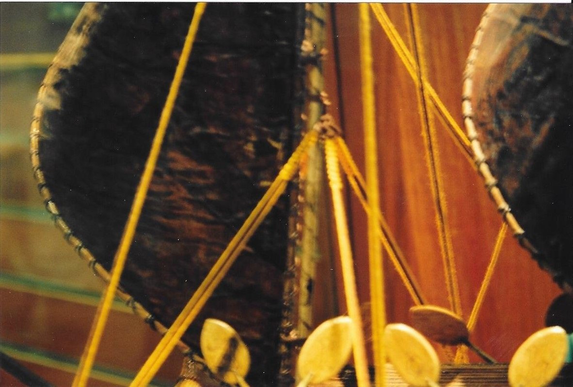
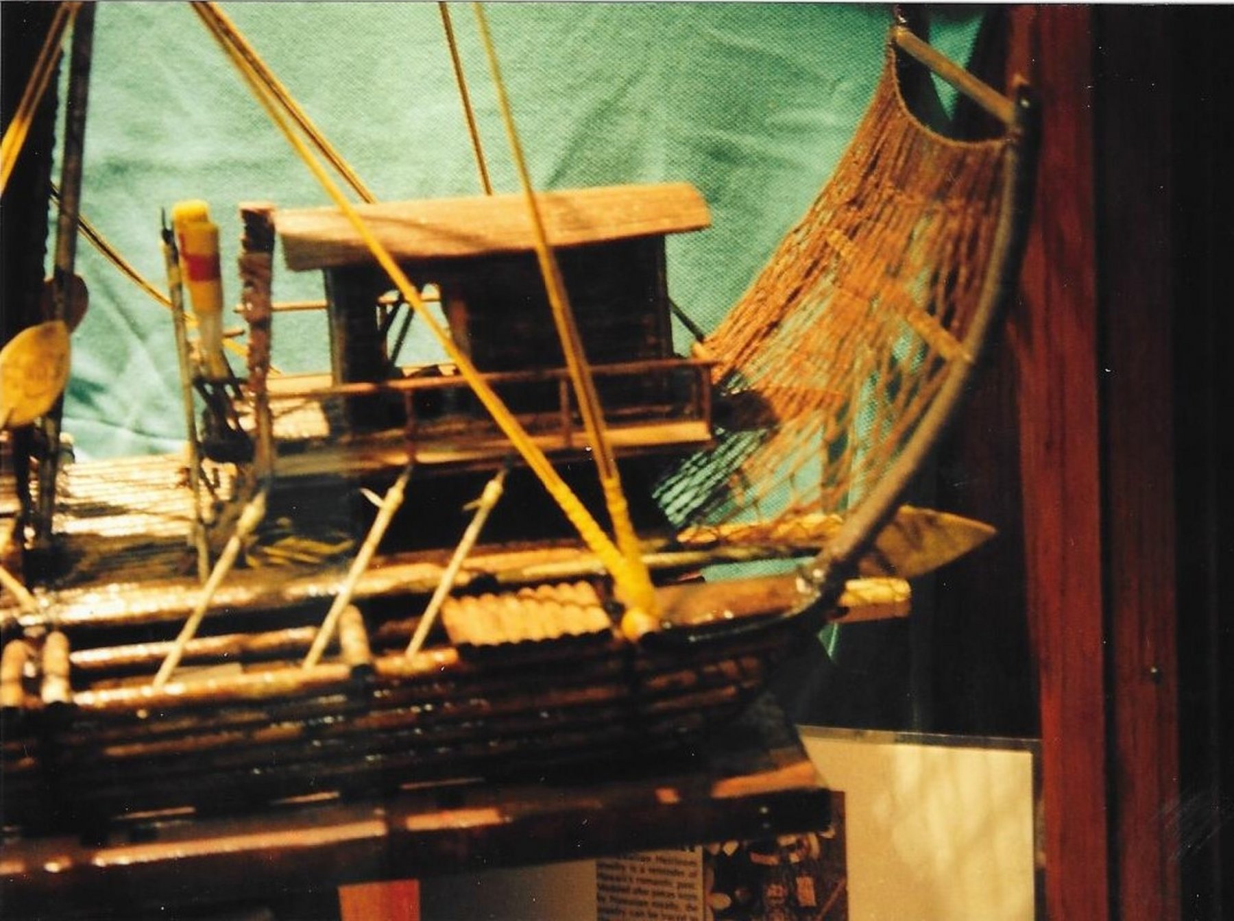
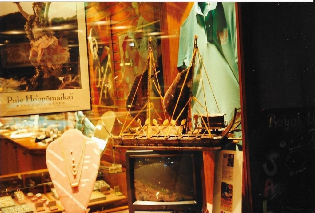
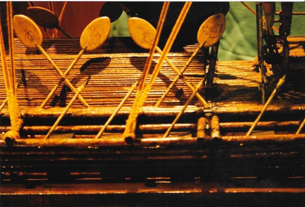
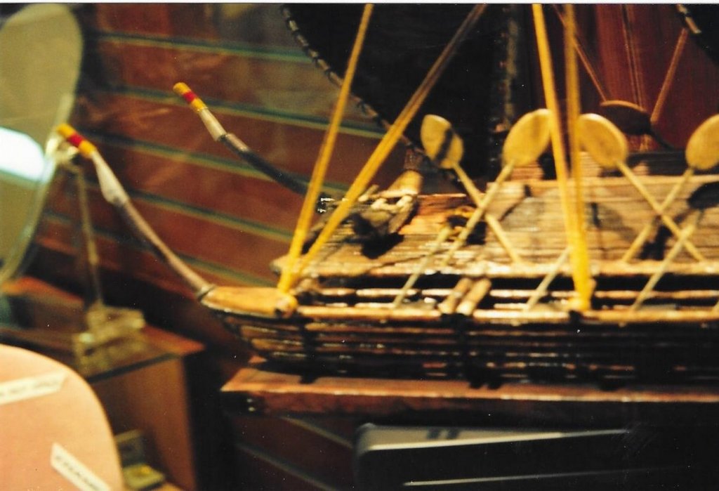
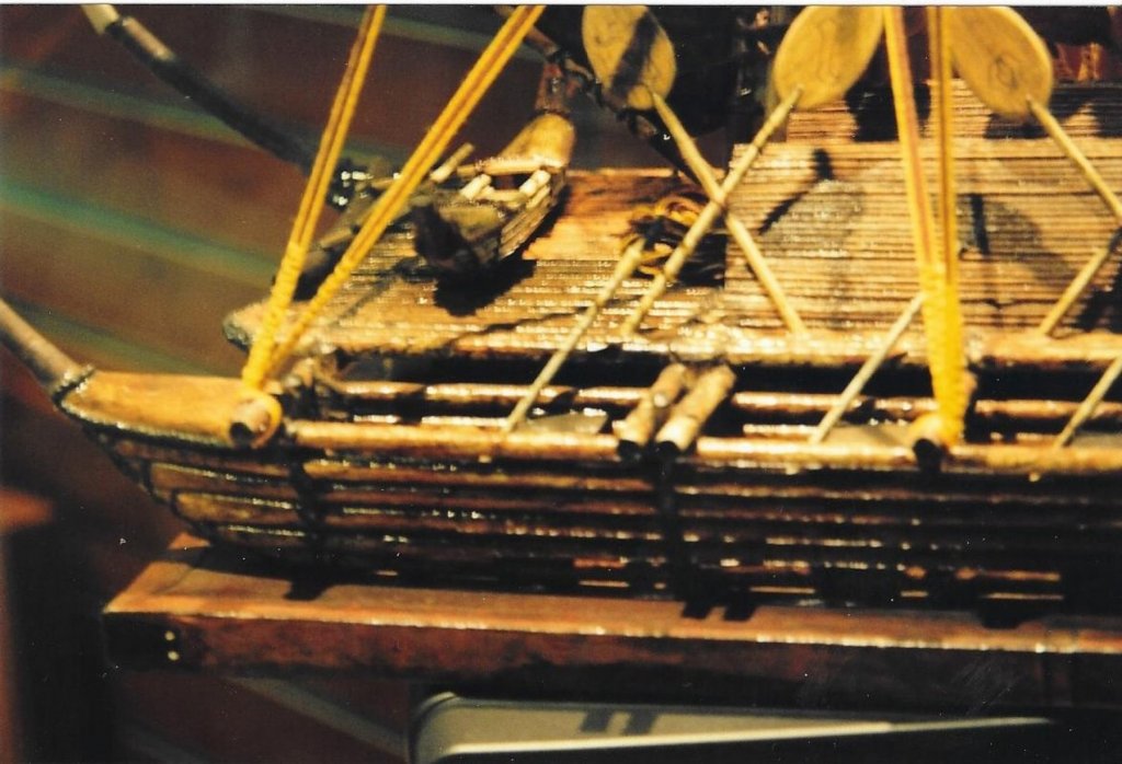
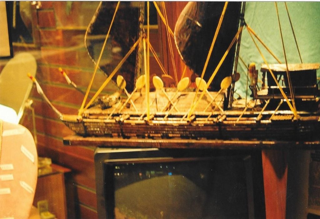
 John Seeing your build log on this war canoe reminded me of a model that I saw while vacationing on Maui many years ago. My wife was occupied in a jewelry kiosk in a small mall just outside of Lahaina. I continued wandering around until I noticed a model of an old ship in a store window that the Polynesians used to get to Hawaii. It was in a shop window so I could only view it thru the glass, but I thought it looked interesting enough to take a few photos of it anyway. I could not tell exactly how large the actual ship was or what scale was used to model it. I talked to the store owner but he only seemed to know that it apparently was made by some local craftsman who claimed that his ancestors sailed there in just such a vessel and he built it as described to him by his grandfather. Who can say for sure, as there were so few written records and most of their history was handed down in stories handed down from their ancestors. I remembered taking the photos, but it took quite a bit of searching to find them again. (no digital cameras back then) Perhaps it would be something to inspire you to build since you do seem to have an interest in such vessels. It appears to be constructed of lashed logs rather that dug out tree trunks like your war canoe. Here are the photos that I took back in November 1985. (Our second of 10 trips to our favorite destination) Dave

-
All they need now is some scale figures of the cast of 1974's Murder on the Orient Express to complete the kit. (Not exactly a bunch of unknowns!) Here is that main cast listing: Albert Finney ... Hercule Poirot Lauren Bacall ... Mrs. Hubbard Martin Balsam ... Bianchi Ingrid Bergman ... Greta Jacqueline Bisset ... Countess Andrenyi Jean-Pierre Cassel ... Pierre (as Jean Pierre Cassel) Sean Connery ... Col. Arbuthnot John Gielgud ... Beddoes Wendy Hiller ... Princess Dragomiroff Anthony Perkins ... McQueen Vanessa Redgrave ... Mary Debenham Rachel Roberts ... Hildegarde Richard Widmark ... Ratchett Michael York ... Count Andrenyi Colin Blakely ... Hardman George Coulouris ... Doctor Denis Quilley ... Foscarelli Vernon Dobtcheff ... Concierge Jeremy Lloyd ... A.D.C. John Moffatt ... Chief Attendant
-
New member with a question about shipping models
BETAQDAVE replied to CJ2S's topic in New member Introductions
Chris, I think that your father must have been very handy with those hand tools. He probably would have made a good finish carpenter. Do you remember what manufacturer produced the kits that he built? It looks like he must have modified them somewhat, as most kits from back then were quite poor, and he would have needed to supply alot of his own ingenuity (something that I personally identify with) and skills to make up for it. Books and magazines back then on modeling were very limited. I'm sure that there was very little in the way of instructions included with the kits back then, and the plans were probably not very complete either. So, for him to construct such a fine looking model makes it that much more of a remarkable feat! Today with all of the research tools available through the internet, forums like MSW, materials and adhesives, and the large assortment of small scale power tools available to us now, I would have to say that we have advantages that your father could only have dreamt about. You are quite justified to be very proud of these accomplishments of his and to be concerned about preserving these fine models. I certainly would be, as besides being something to remember him by, the ships appear to be finely made models of some very famous ships. (Perhaps a local museum could be persuaded to help with the shipping if you offered to donate the models to them. Then you and many others would be able to enjoy seeing them now and in the future.) Dave By the way, welcome to MSW. -
That was one of my first reference books and still one of my favorites. Some of the more confusing details are explained so that a novice can understand them. Another book that is also good for beginners is Ship Modeling Simplified by Frank Mastini.
-
Yes Yves, that may be true. However, now that I am well into the project I am quite happy that I did it this way. It is actually quite a bit of fun doing it this way! Apparently it is similar to working with a preformed fiberglass hull. As I mentioned in my previous posts, I did something similar to my Constitution model that is laid up in dry dock. On that ship everything that came with the kit was used except for the decks, rigging, and masting. For the Wanderer, I decided to go all out with the exception of the hull. Most of the plastic parts were poorly formed, especially the masts and spars which had thick preformed sails moulded right to them. The shrouds and ratlines were also of preformed plastic which I also found to be quite unsightly. However, the plastic parts will serve as a 3-D sample to duplicate. My friend that I am building it for most heartily agreed. If not for him, this model would still be ignored and sitting on the shelf. Other than the easily corrected warp to the hull pieces, we both thought that the details were excellent. The copper sheeting was a little overdone, but a little sanding was all it needed to tone it down. The fact that it has all of these issues to solve and improve on is one of the things to me is that is the most fun to do! Dave
-
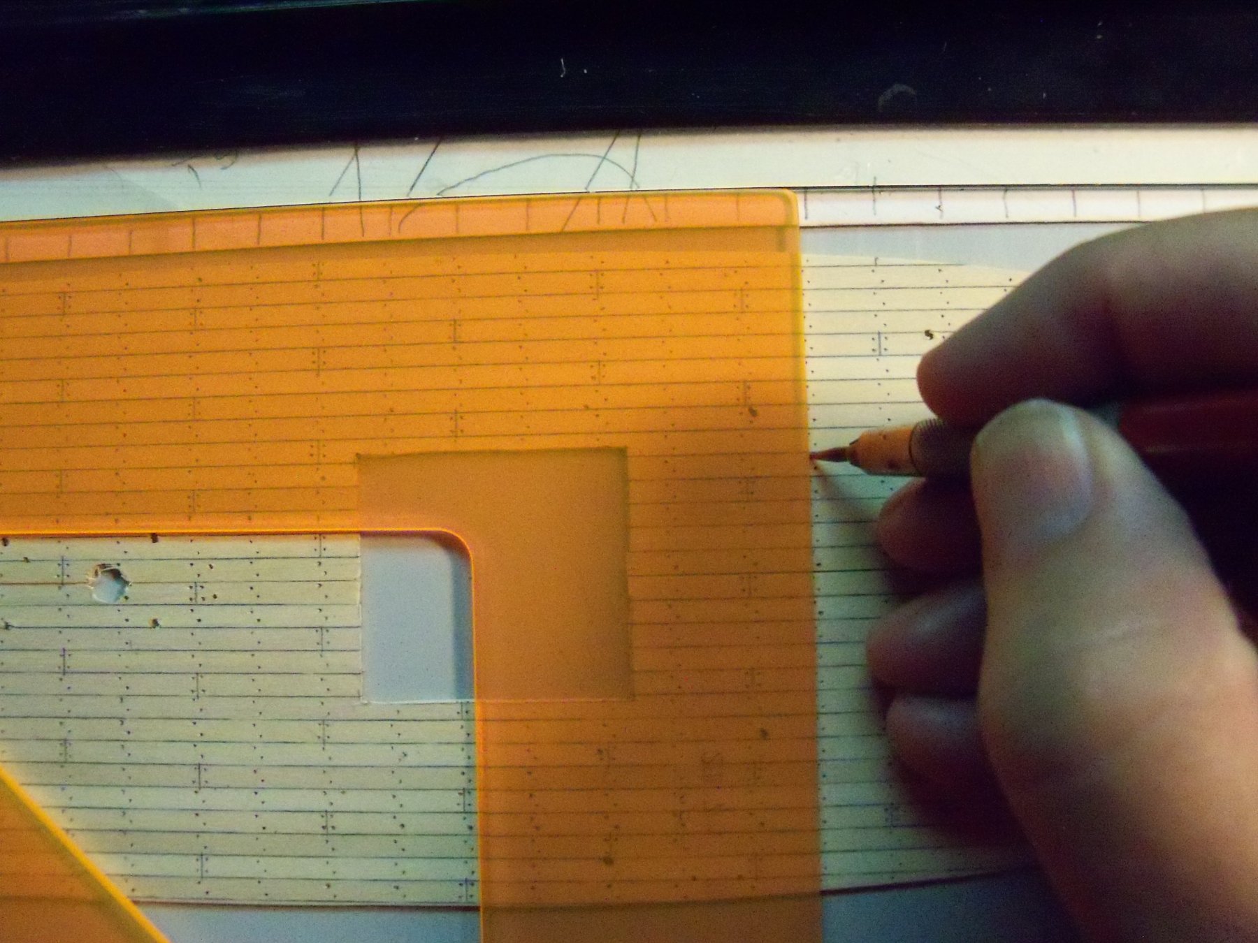
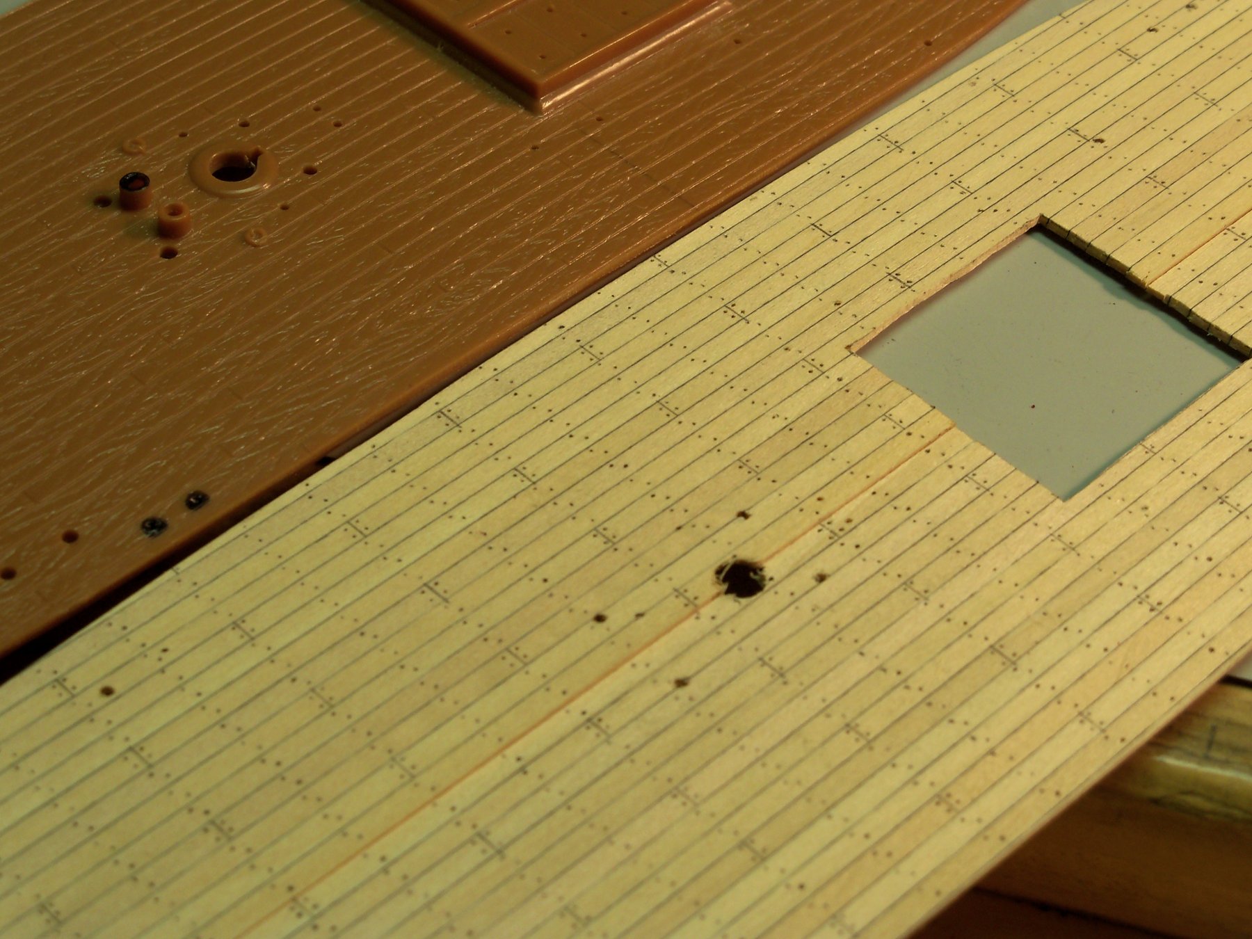
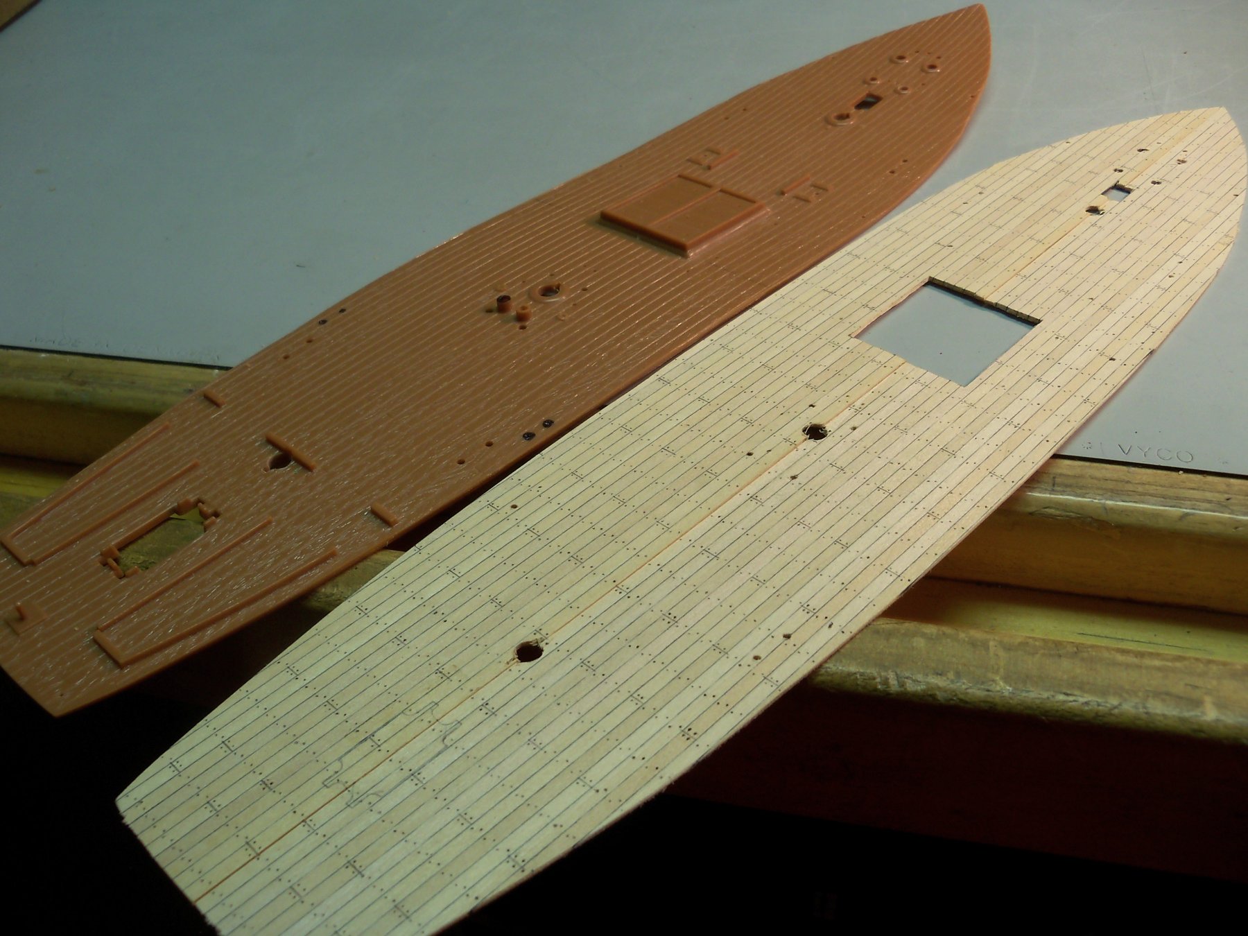
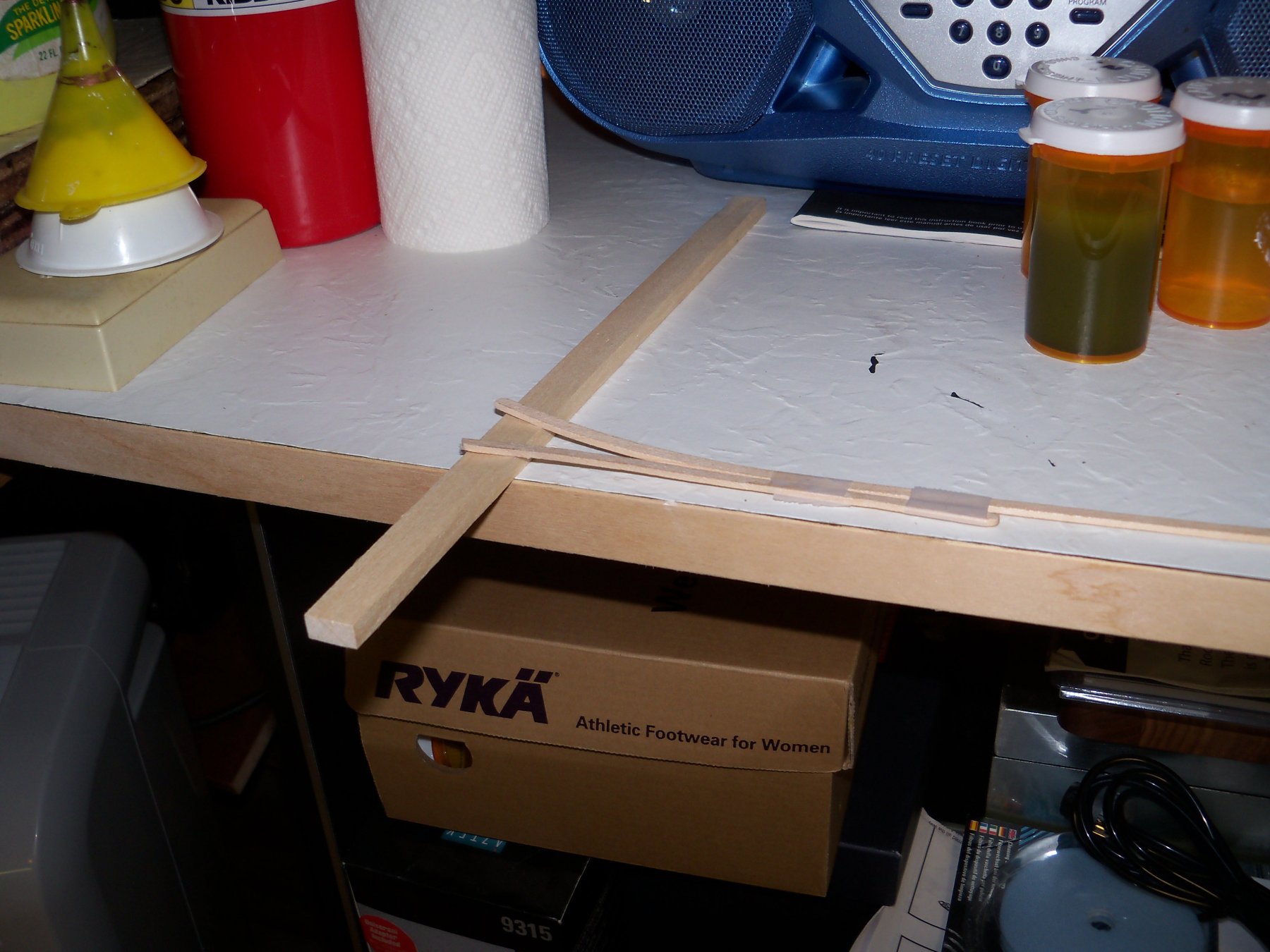
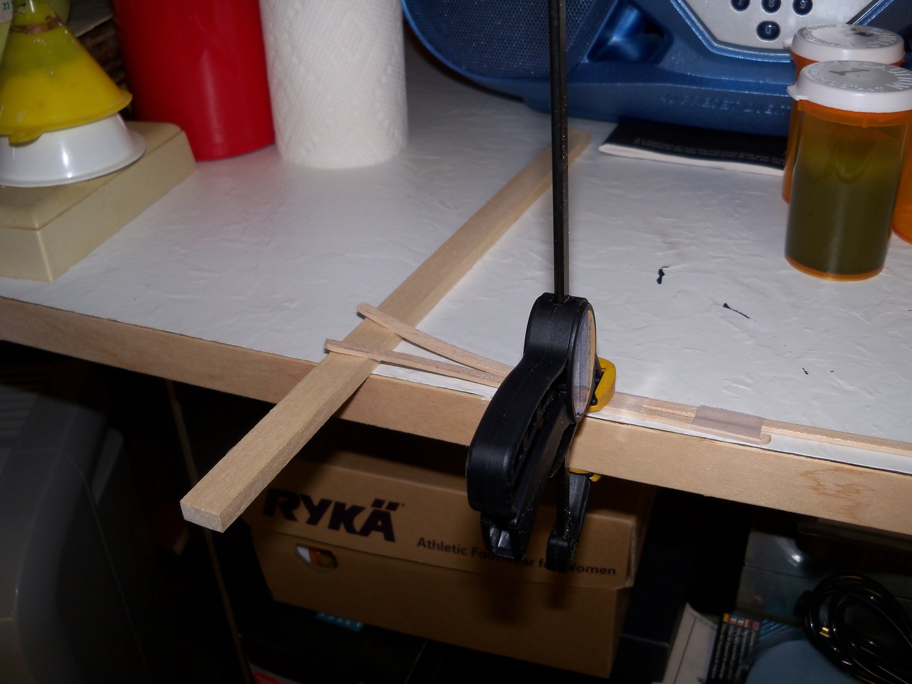
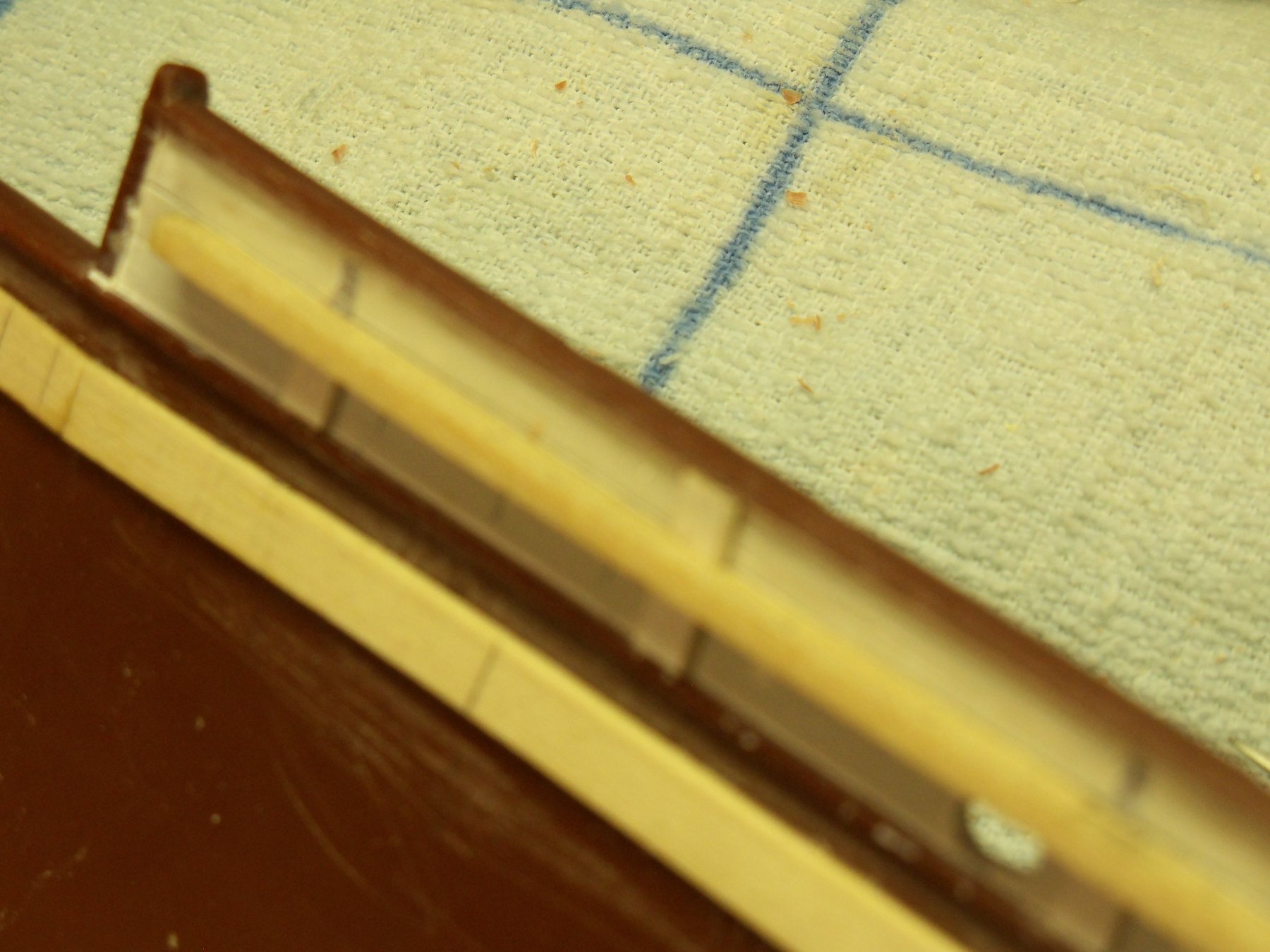
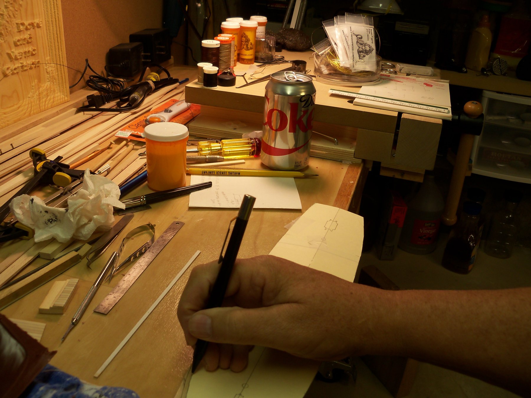
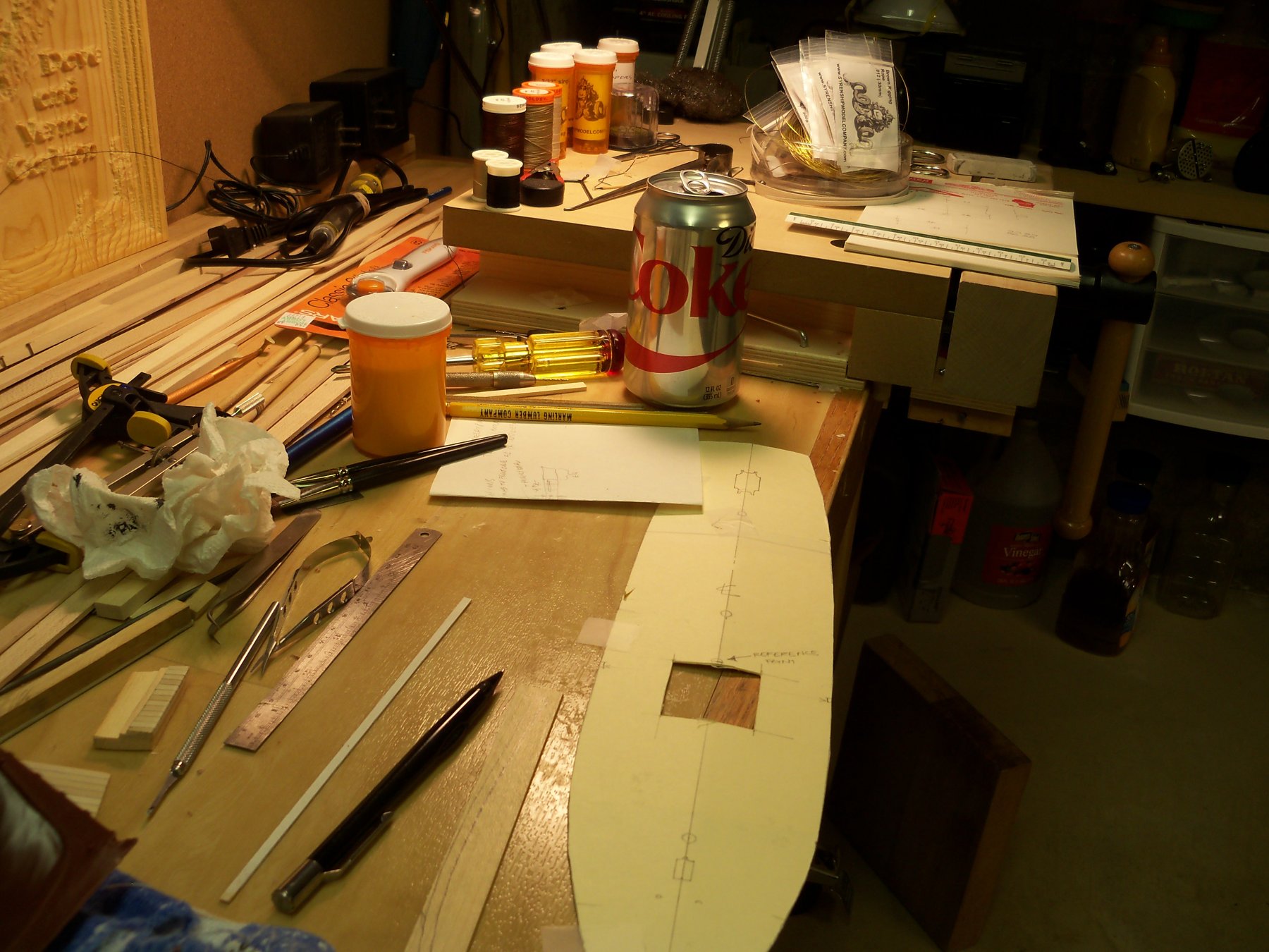
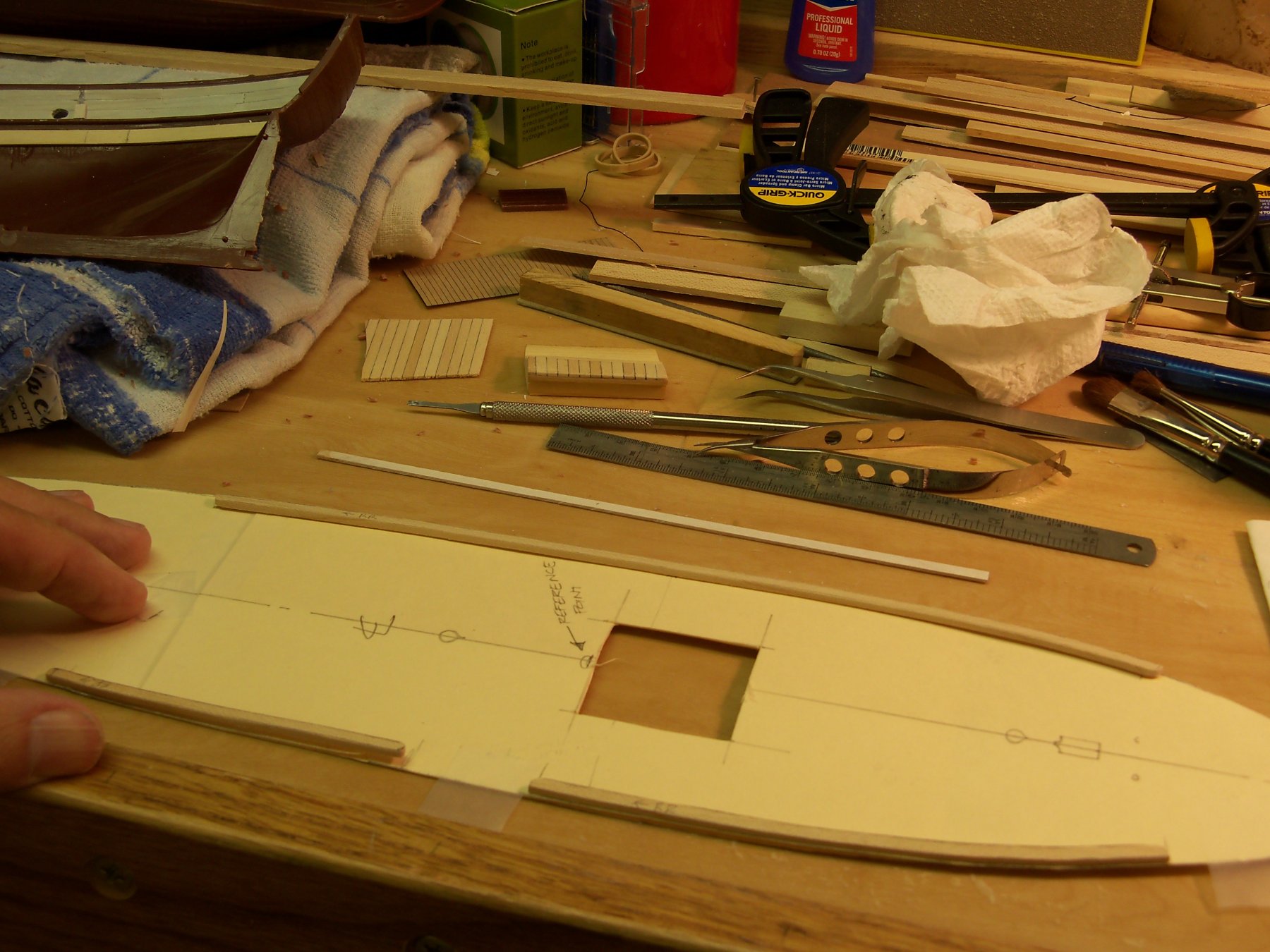
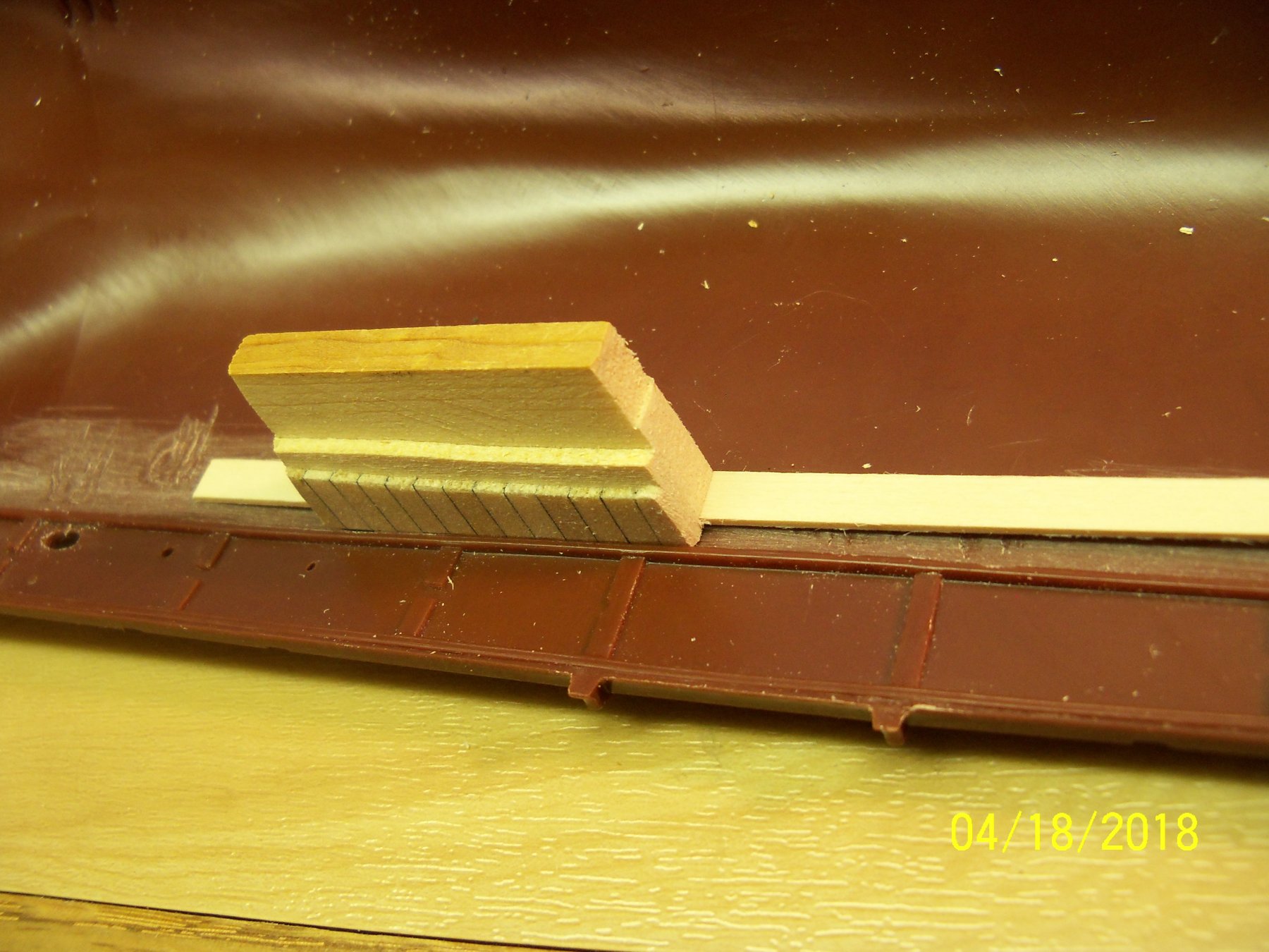
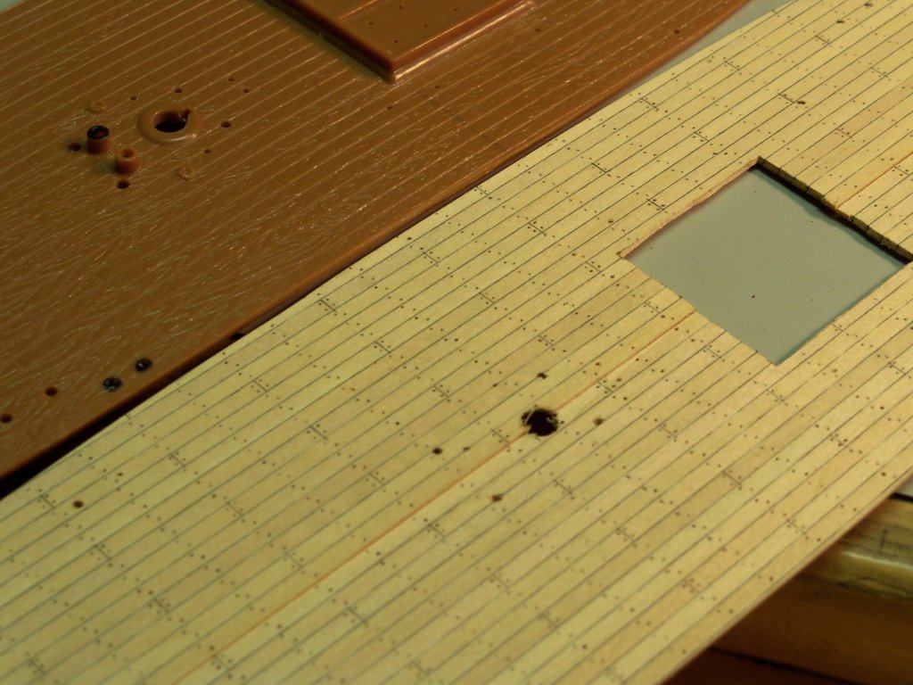
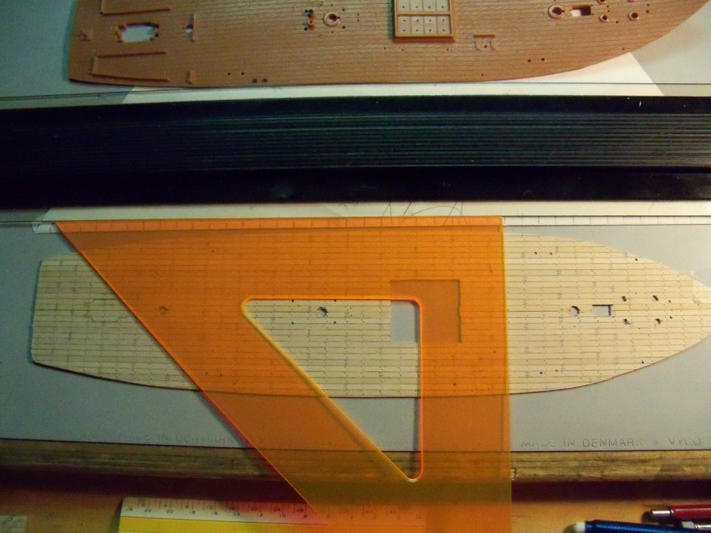
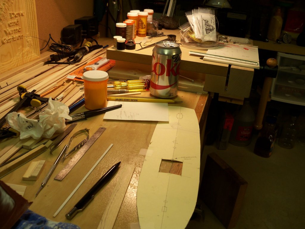
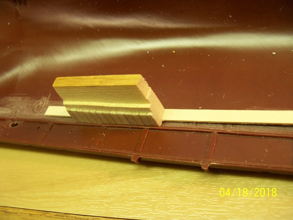
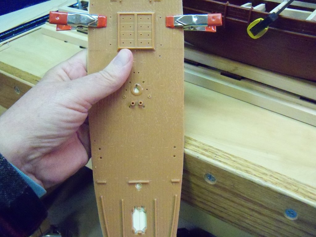
Well, it looks like my ship modeling will be delayed somewhat now. My access to my shop will be limited for a while by the fact that my elevator is now in need of either some major service or a complete replacement! It’s about 16 or 17 years since it was installed, so it’s apparently nearing the end of its service life. Originally it ran around 12K plus installation and remodeling of that area of our home. The estimates for repair are about 10K. I haven’t gotten a quote on a new unit yet, but I guess I’m leaning towards its placement with a new unit with increased weight capacity. Someday when I get promoted from my manual chair at a mere 40 pounds to a power chair like my brothers’ at around 450 pounds, the existing unit wouldn’t be able to handle the extra weight. So as it stands now, I’m limited to only using it a few times a week. (I guess it’s like adding too many miles to your car at this point.) It may cost a bit more to replace it with a new unit now, but as I see it, why spend the 10 K for the repairs now when it will soon need to be replaced anyway. (Who has an extra 10 K just lying around anyway?) However I did manage to switch to doing some things in my office that don’t require trips to the basement shop. Working on the finish deck is one of them. I sketched up a plank layout pattern based on a three plank shift with the frames at about three feet on center and a basic plank length of about 24 feet. Taking a long paper strip, I placed a mark at three foot centers to scale. The strip was taped down to my desk along my parallel rule. Then the two deck pieces were taped together on their backsides and taped down to the desk with the centerline also set parallel. Now by using a triangle to transfer the locations of the beams to the deck, it wasn’t necessary to draw any lines on the deck that would need to be removed later. (Remember, the decking is just soft basswood at only 1/32” thick.) The photo below shows my setup for this operation. I started with one of the center planks and using an F softness very sharp lead in a mechanical drafting pencil, marked the plank end butt markings at 24 feet lengths based on my previous sketched layout. Skipping three planks, I marked the fourth plank the same way. This was repeated for the full width of the deck. Now moving the triangle over two marks, the butt was moved down one plank. These plank butt joints were then marked for 24 foot lengths and the process was repeated until all of the butt marks were marked. (Allowances were made along the way so the plank lengths were at least four feet.) I then went back to all of the butt joints with a narrow straight chisel and pressed it lightly into the marked line just enough to leave the impression of a joint. Once this was done the pencil lead was given a sharp point, pressed into the plank at each butt joint for two treenail impressions at each end and twisted lightly in place. Using the triangle again, similar impressions were made for treenails over all of the remaining deck beams. Setting the triangle just to the right of the beam location marks, one treenail impression was made in the near edge of each plank all the way across the deck. By shifting the triangle just to the left of that same beam location, another impression was made in the far edge of each plank all the way across the deck as shown by the photo below. Now, this procedure was repeated at all of the remaining beam locations. This was done to keep all of the impressions in line with each other all the way across the deck while showing a staggered pattern with two impressions per plank as shown in the photo below. Here is an overall photo of the deck as it stands now. My next step will be to stain and poly the deck.


- 107 replies
-
- 10
-

-
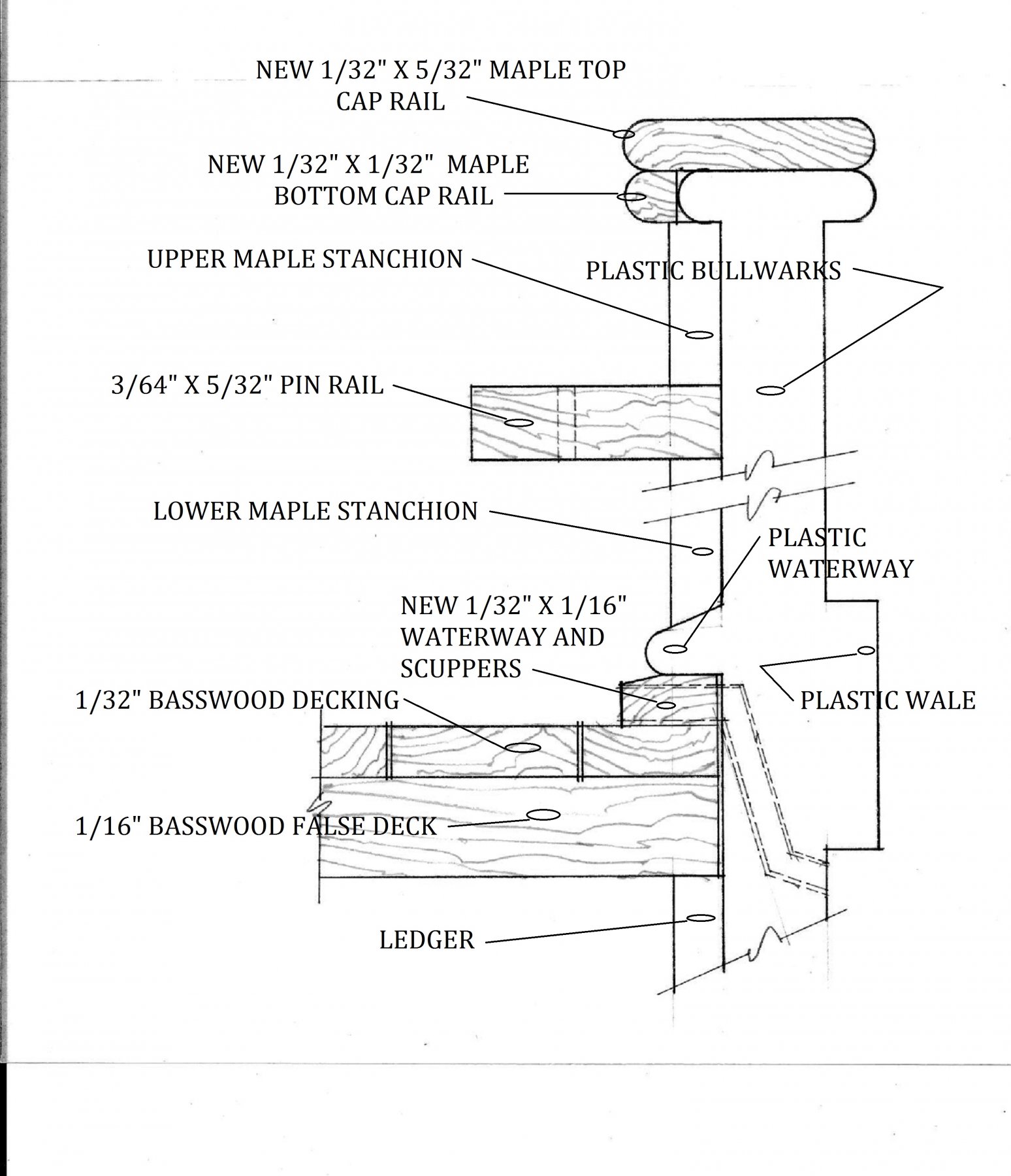
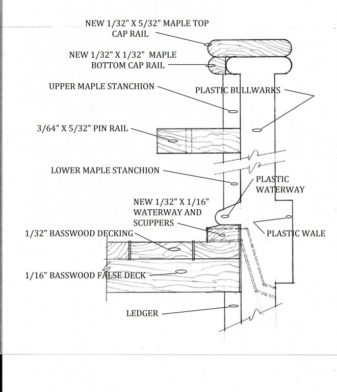
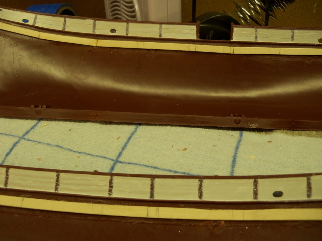
(Here is a clearer photo of the problem of the projecting stanchions tops.) Actually, I literally did have to go back to my drawing board to come up with a solution. Going back over my research notes and photos, I started this drawing below to figure out how to take care of the stanchion projection, but found that it also revealed some other unforeseen problems. The first problem was that the cap rail on the plastic model was just a single rounded over edge, but I found that the cap rail actually had somewhat of a double beaded edge. The second problem revealed was that the waterway was too small and there were no drain scuppers! By adding a 1/32” square piece of maple to the inside face of the plastic cap rail, the exposed end of the upper stanchions will be concealed. Then, by adding 1/32” thick maple cap rail over the top of the plastic rail and wide enough to cover the extra 1/32”, it will be possible to make it a cap rail that can have the double beaded edge formed on it. To adjust the waterway problem, I will add a strip of 1/32” x 1/16” maple that projects out a little beyond the plastic one to make it thick enough to allow the scuppers to be added Problems solved, right? As I mentioned in the previous post, none of these problems can be handled right now due to the warped hull. They will have to wait along with the pin rails until the hull can be assembled. But wait! Now I realized that the deck itself may also be a problem to install. When adding a wood deck to my Revell Constitution, the installation was fairly easy. The rear transom was a separate piece and allowed the deck to be slipped through that gap. Then the transom was put back in after the deck. However, the Wanderer has no separate transom, it’s moulded right into the hull and there is no practical way to cut it out, so a different method will be needed. After some more thought, and rejecting several different ideas, I decided to make two additional cuts across the deck that would align with the rear deckhouse partition and thus be less noticeable. Since the deck is already split down the centerline, it would allow me to slide the front two deck sections on top of the deck beams and under the plastic waterway. Then the two rear deck sections could be similarly done. Once all four sections are installed, the new waterway can be wedged into place and drilled for the scuppers. OK! Now that that all of those problems seem to be worked out, I can get back to cutting and fitting the rest of the deck beams. Because the waterway will now be 1/32” thicker, I will need to start by trimming down the top edge of the ledgers to lower the beams. Time to get back to the bench and start doing some actual modeling again!


-
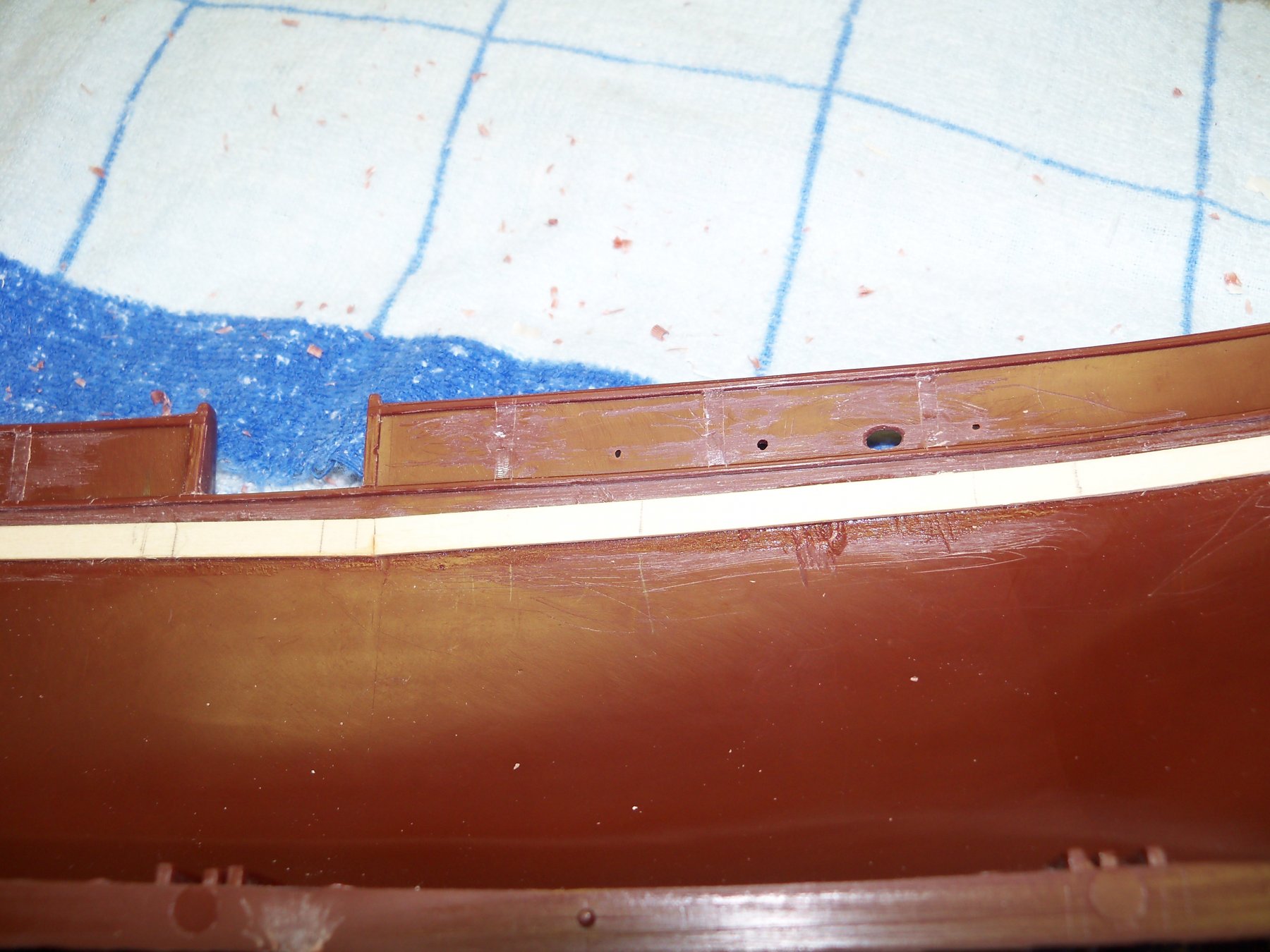
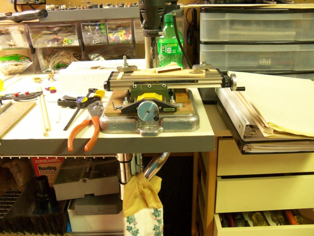
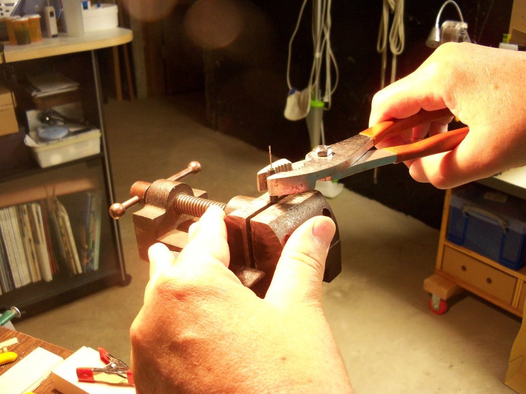
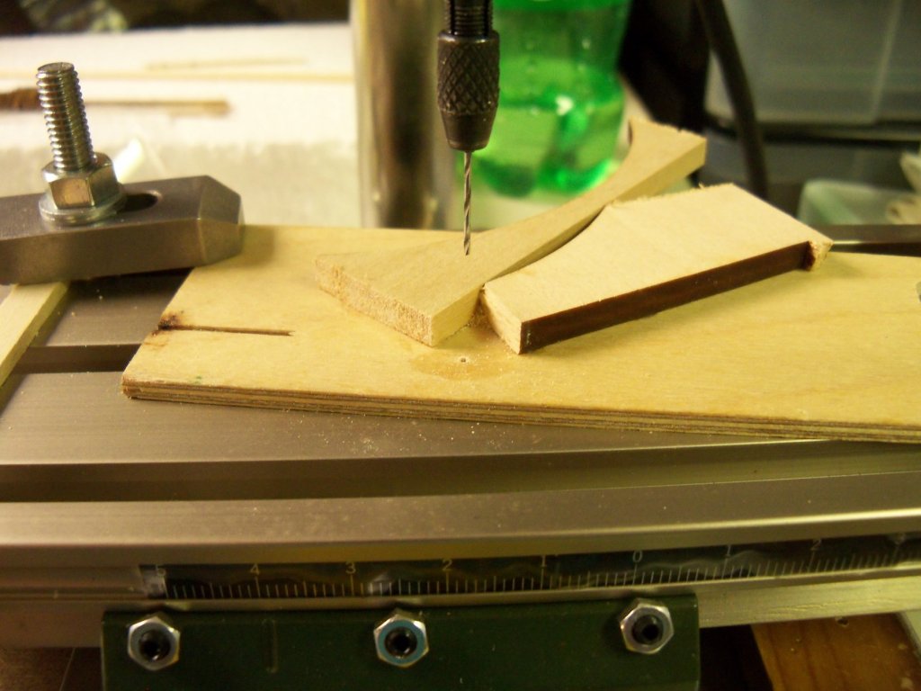
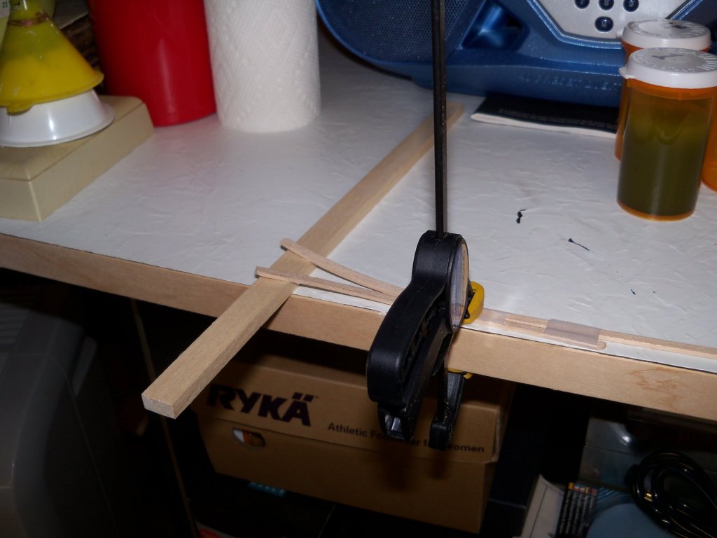
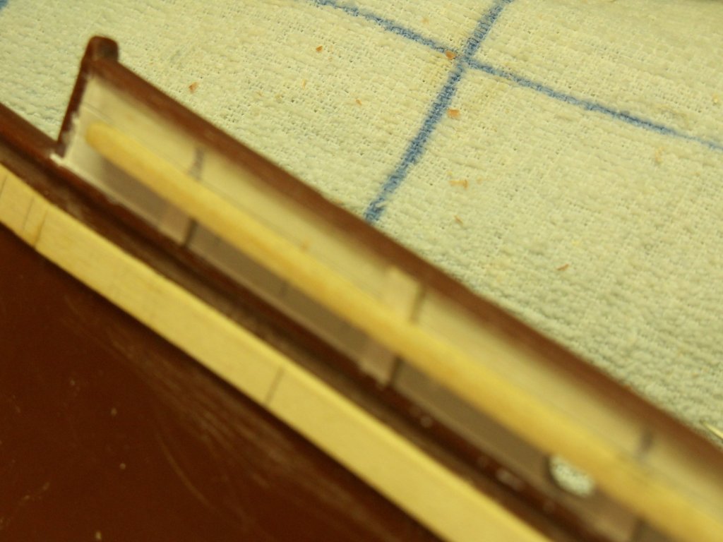
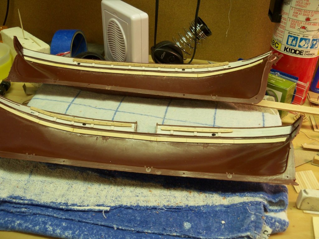
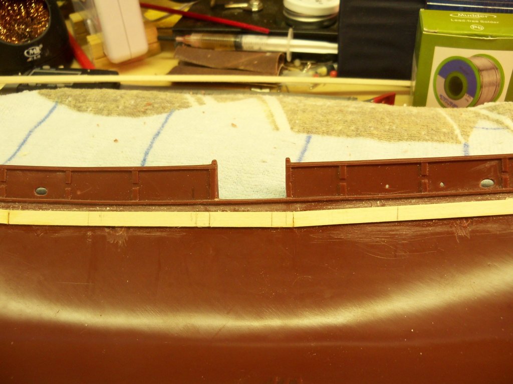
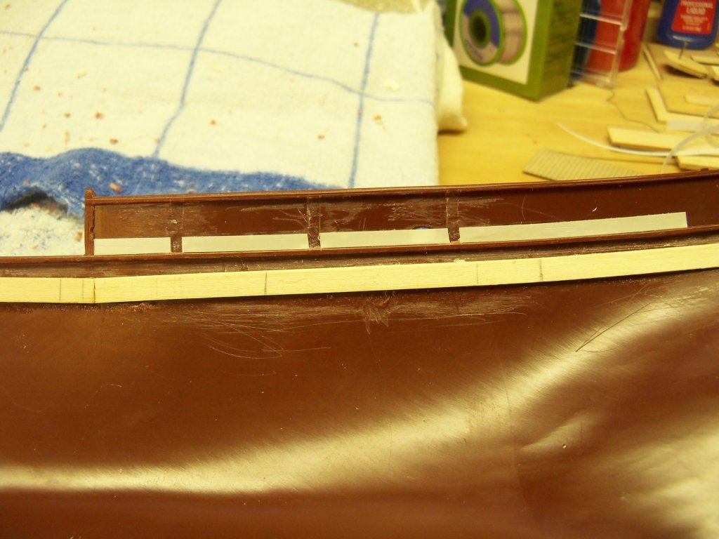
OK, now for a little more work on the belaying pin rails. First step for doing that was to measure the belaying pin shaft diameter. I used my digital micrometer and came up with .74 mm. The #66 drill bit proved to be the best as it measured .83 mm and would allow the pin to seat easily and still not allow the crown of the pin to fall through. As the rails were curved, it meant that I needed two bearing points pretty close together that would allow the rail to slide along and keep a consistent distance from the edge. I set up a simple jig with some scraps by spot gluing two pieces of basswood to a small piece of plywood. Taking my jig to my Dremel drill press with my Proxxon X-Y table, I clamped it in place. I mounted the drill bit in a small collet and installed that into the Dremel collet. (By the way, my MD has weakened my grip to the point that I always need to use pliers to tighten small things like collets which can be a little cumbersome, but such is life I guess.) Using the adjusting wheels, the jig was then maneuvered to line up with the drill bit. I almost forgot to set the drill depth so it wouldn’t go through the plywood base of my jig onto the Proxxon table, but remembered just as I was starting to drill the first hole! Sometimes when you get in a hurry, you find yourself doing something stupid. Most of the time if you don’t take the time to think things through ahead of time, you end up having to do it over. Which brings to mind one of my favorite sayings: Why is there never enough time to do it right, but always plenty of time to do it over? Well anyway, this time I was able to catch myself in time. The other two rails were then done the same so the next thing to do was to steam bend the two long rails to match the shear of the deck. I simply taped the rails together side by side with the top sides up. Then I put a scrap of wood (about twice as thick as the amount of bend needed) on my counter under the front end of the rails. I would normally have used a heavy weight on the rails right where the curve started (as most of the rail run was relatively flat), but this time I just used a bar clamp instead. (I guess I had just mislaid the weight somewhere) While trying a test fit with the short pin rail with the top piece of stanchion in place, I discovered that even though the stanchion was only 1/32” thick, it still projected slightly beyond the inside edge of the models’ cap rail. (maybe a little hard to see in this photo) Hardly a proper detail for my model! Also, the hull sections have such a pronounced warp to them that I won’t be able to actually install the pin rails until the hull is assembled! I need to have a closer look at this problem to come up with some kind of solution to this new glitch. At this point, I will just use the short pin rail as a spacer for fitting and installing the upper portion of the stanchions so the cap rails can be set into the gap later when the hull is put together. Giving the pin rails three coats of the thinned white paint and sanding each coat, these were just set aside to dry for now. So, I guess it’s back to the drawing board as they say, for a bit to ponder a solution to this new problem.

-
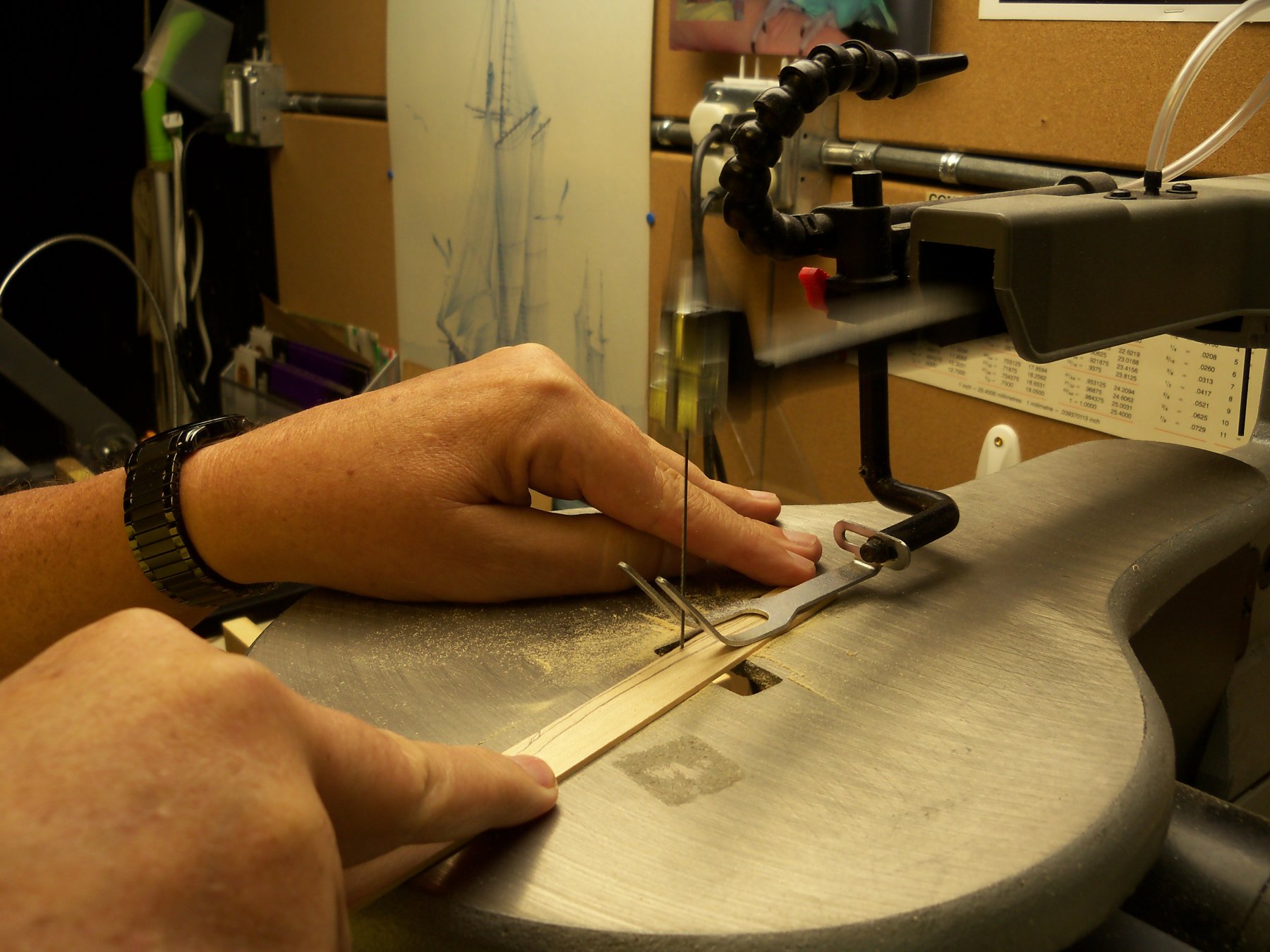
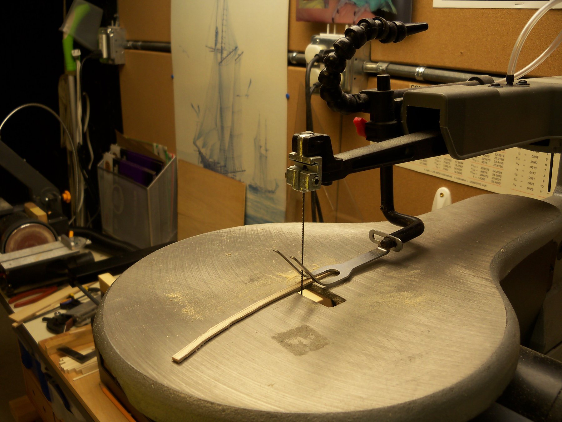
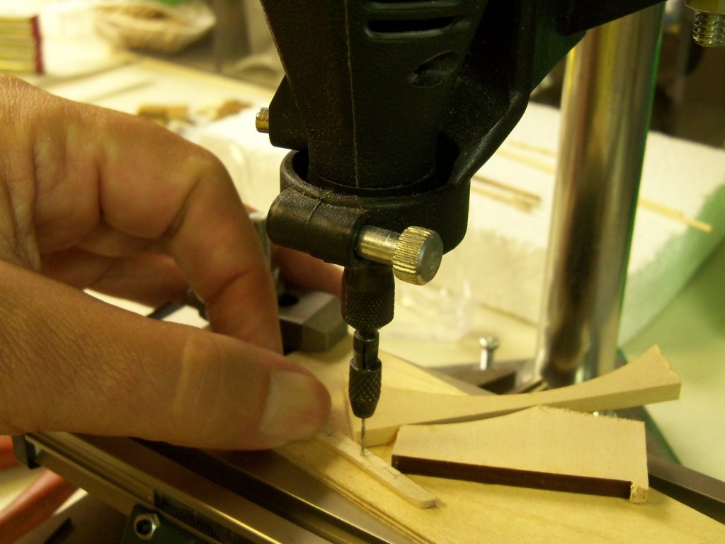
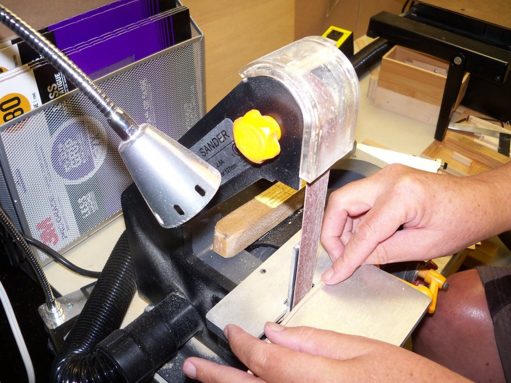
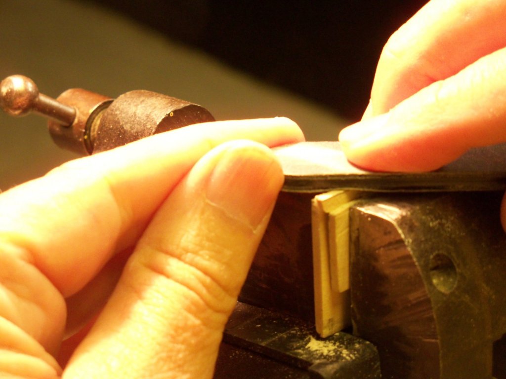
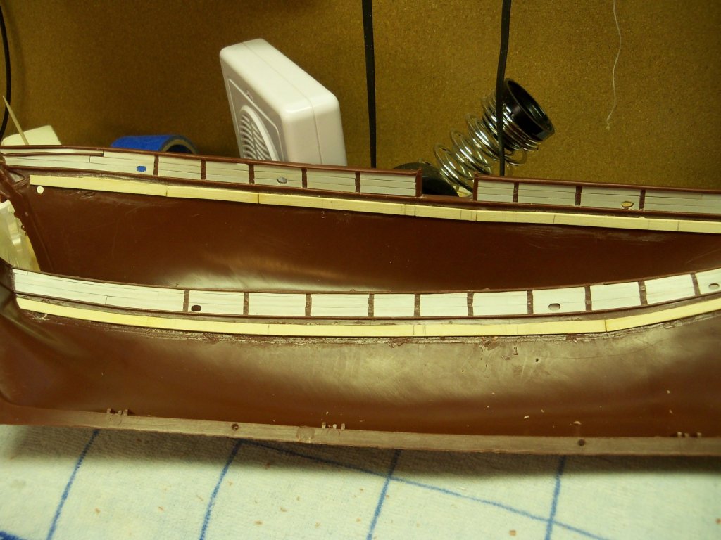
Wow! Somehow I found a couple hours free, so I could work on the pin rails. The first step was to shape the rails to the curve of the bulwarks. Taking the manila template in hand, I held it in place up against the hull pieces and marked the locations and lengths of the rails onto the template. I taped it down onto a strip of maple (previously sanded down to 3/64” thickness) and traced the outline onto the strip for the outside edge of the rail. I marked 5/32” (the width of the rail) on the template at both ends, then shifted the template to these marks and traced the same curve onto the strip again for the inside edge. Now I had both edges of the rail drawn on the strip. Taking the strip to my scroll saw I cut it out, keeping the blade about 1/16” outside of the lines. Then it was off to my 2 inch belt sander where I sanded it down just short of the lines. Taking the rail to my vice, I smoothed out the curve with a rough sanding stick and just removed the lines. Switching to the finer grade stick I gave it the final shape. The procedure was then repeated for the other two rails. At this point I had the overall shapes, but I still needed to locate the holes for the pins. Holding each rail in their proper position on the hull, on the underside of each rail, I marked the location of all the stanchions. Since I wouldn’t be able to put a pin where the stanchions were located, I laid the rail upside down on my bench to mark the pin locations between them. I decided to put two pins evenly spaced at about 3/8”between each stanchion which would give me the proper number of pins. I marked the spacing for the holes on their bottom sides for all three rails. This photo below shows all of the rails at this point in their proper locations on the hull. Oops, times up! When I return I will be drilling the holes for the pins.


- 107 replies
-
- 10
-
-
Copper plating tape.
BETAQDAVE replied to Burroak's topic in Building, Framing, Planking and plating a ships hull and deck
It appears to me that you have too much overlap which will really accentuate that overlap. They would normally have be lapped only an inch or so on the actual ships. You may also have gotten you fingers on the adhesive side of the tape which reduces its adhesive properties. (If you get your fingers on the underlying copper tape, the oil from your skin leaves a coating that the overlapping layers can't get a proper grip on.) I usually wear thin nitrate gloves and use tweezers to place them. Before you get too drastic and start over, you can try pulling back the loose flaps and applying small amount of contact cement with a tiny brush or toothpick to them and pressing them back down, being careful to wipe off any excess before it dries and then re-burnishing the entire hull. Putting on a coat of Dullcoat or similar product after you are done, as Joe suggested, would probably be a good idea also. Good luck. -
Jesse I ordered them off ebay from a site labeled globalfilmcorp1. It took about 4 days to ship and was about $24 inc. shipping for the 2 rolls. As I have used them now, I would say that they are just what I expected and am quite satisfied with them. Dave
-
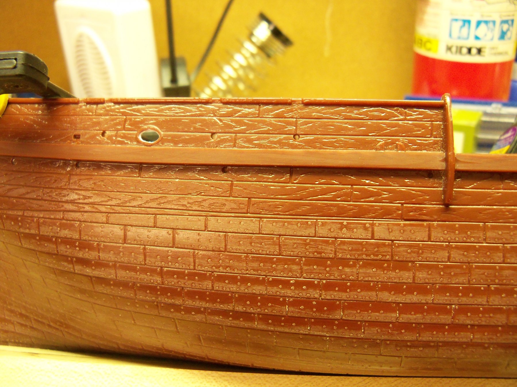
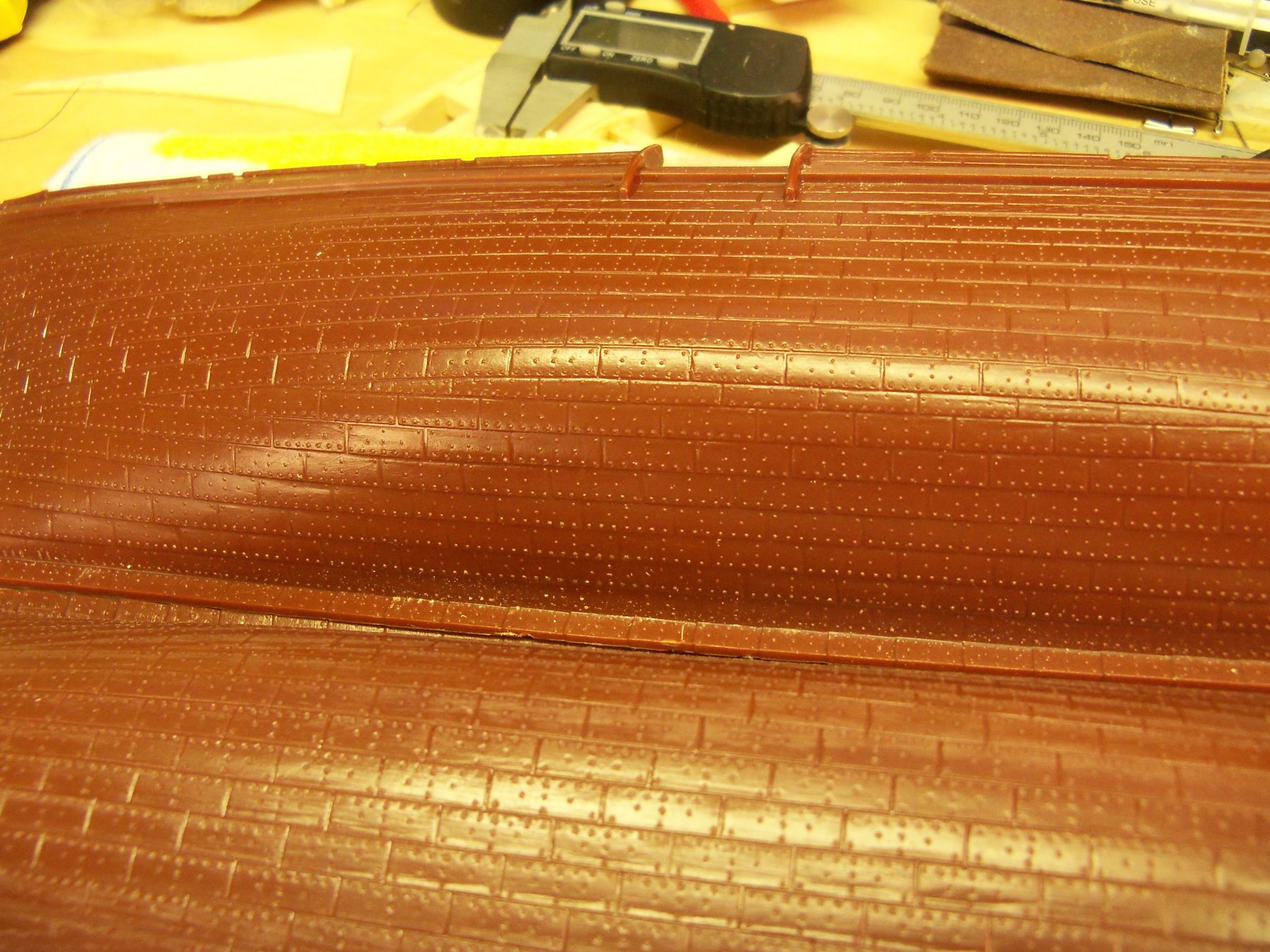
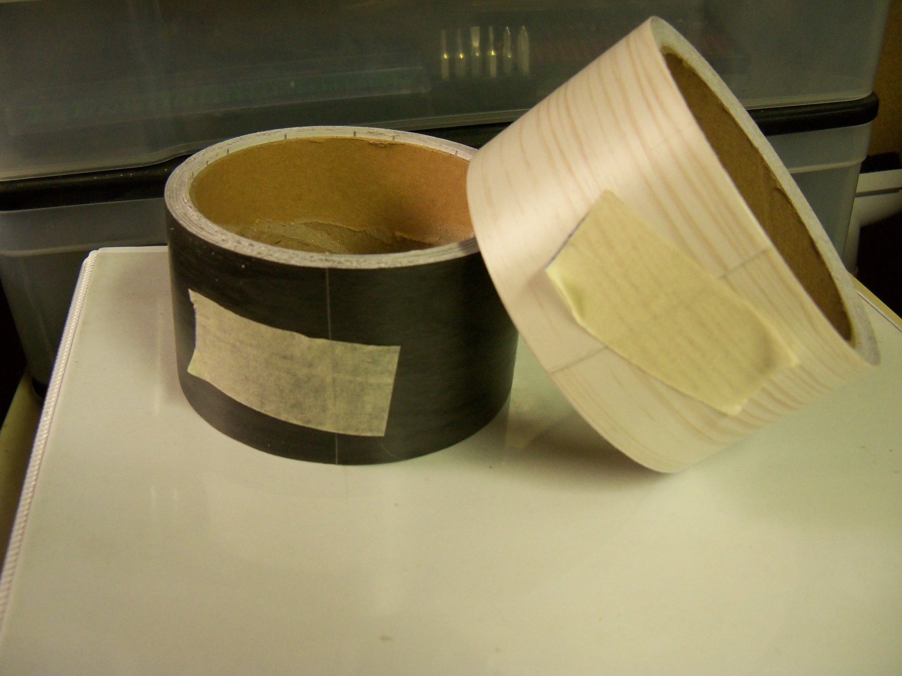
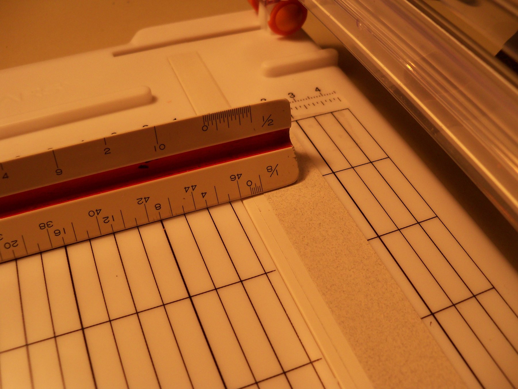
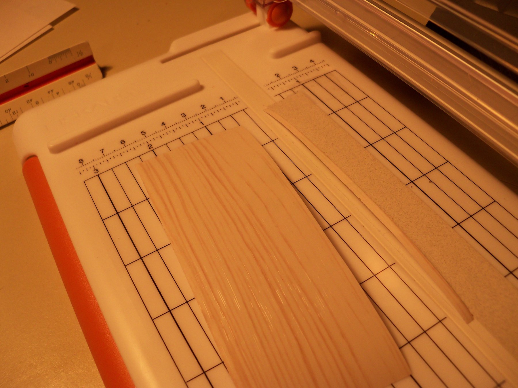
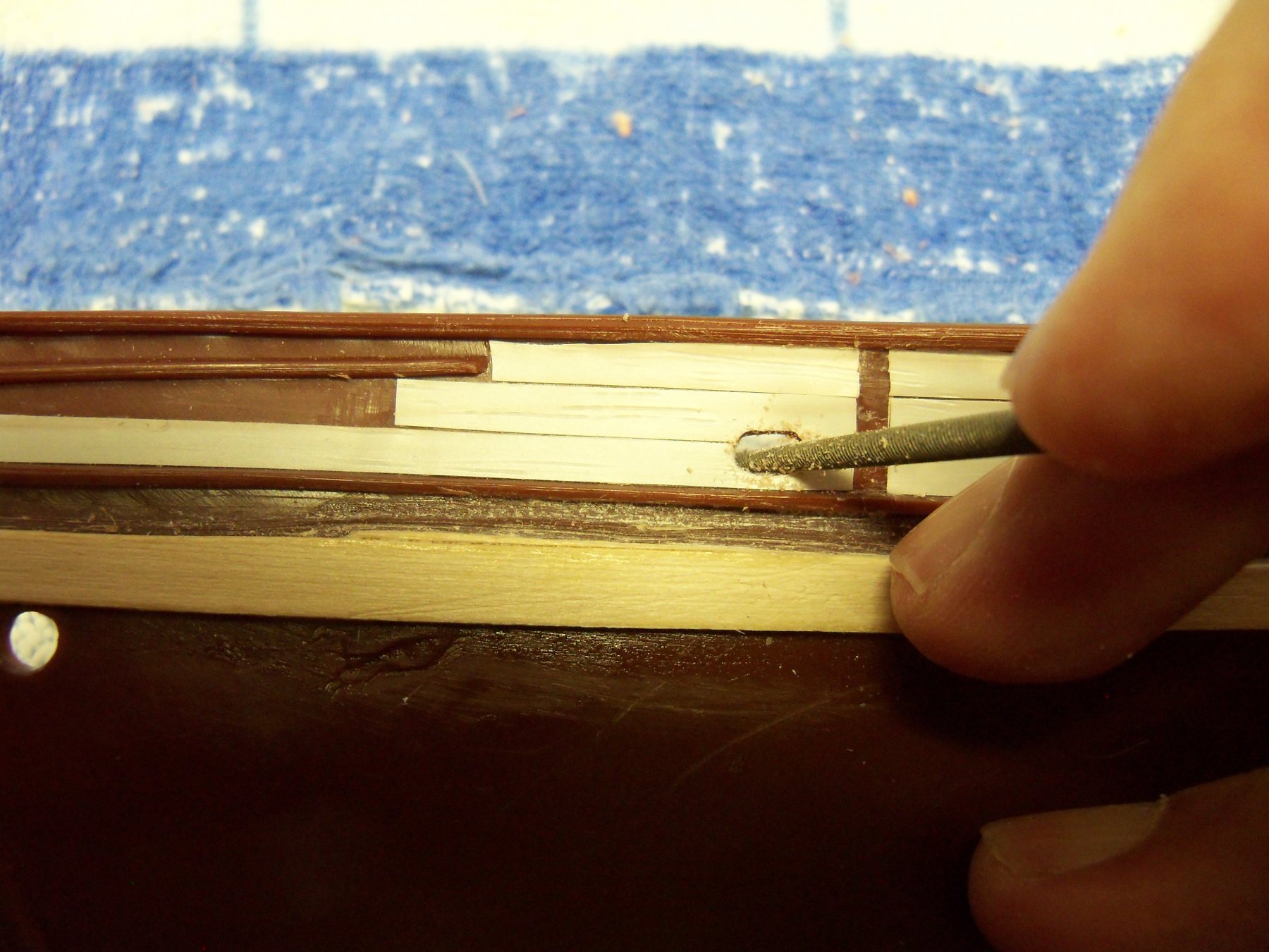
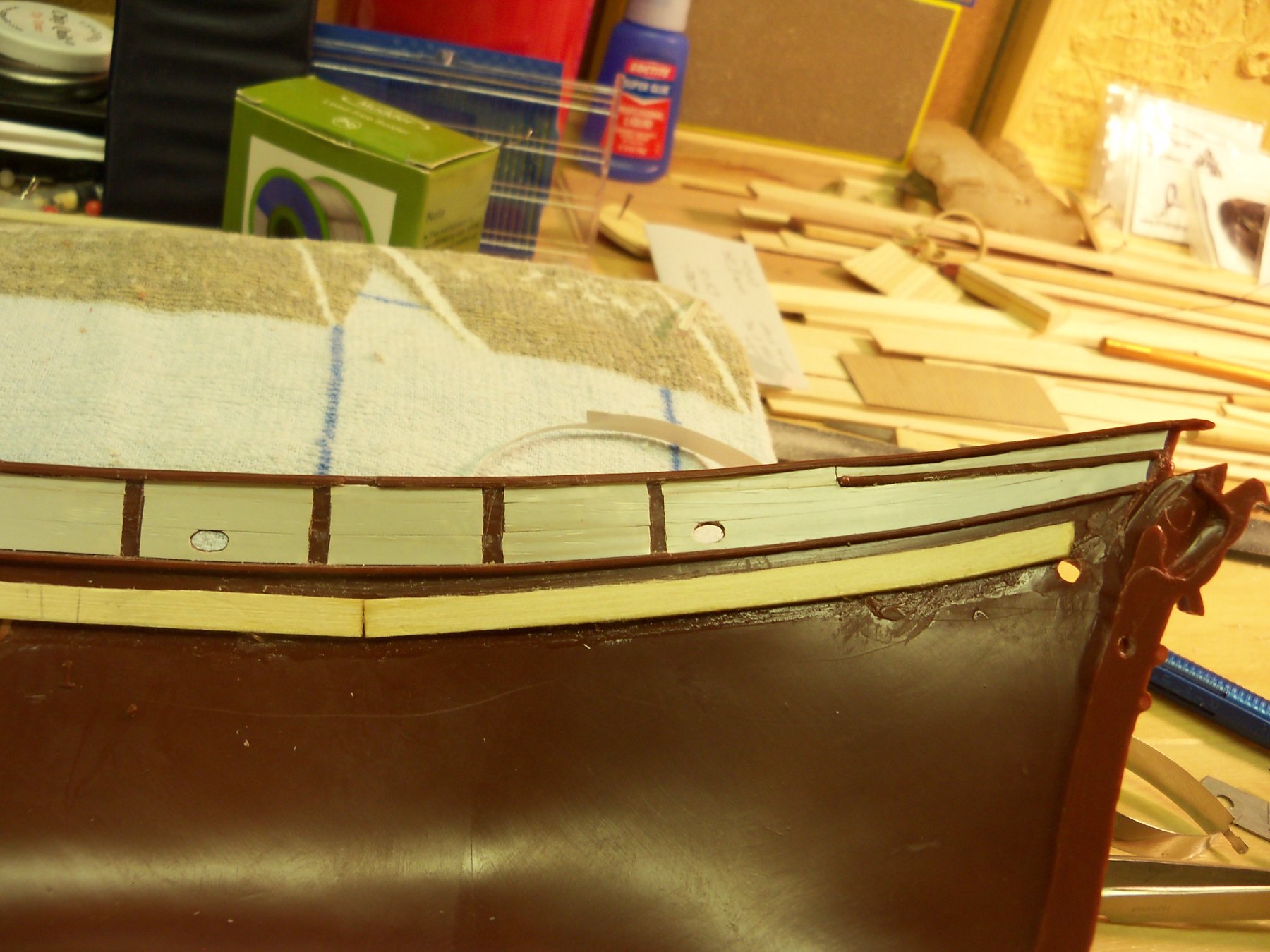
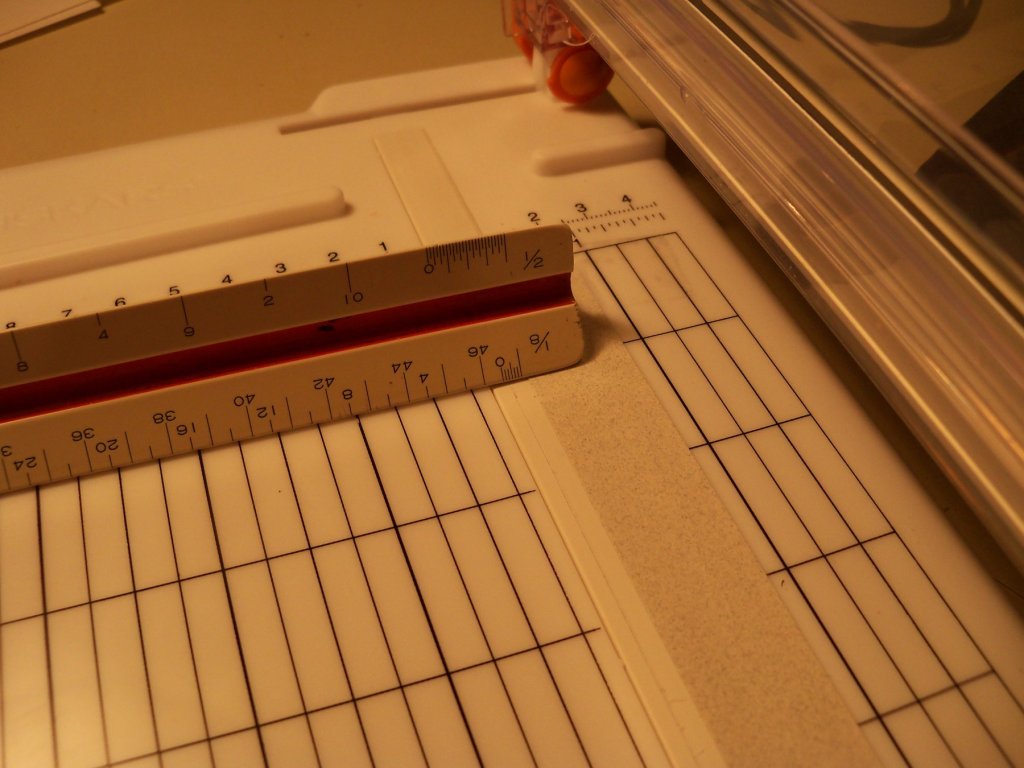
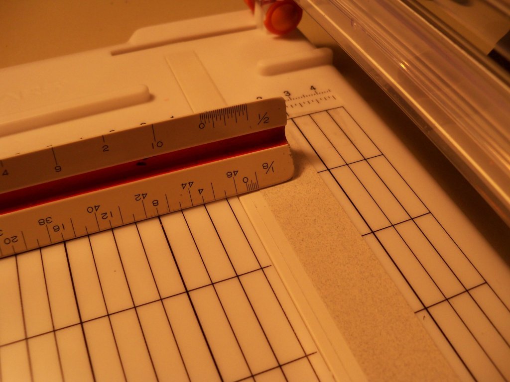
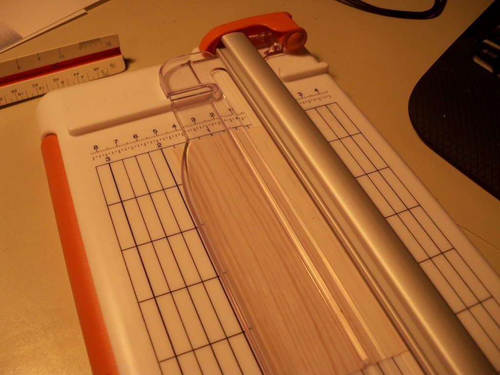
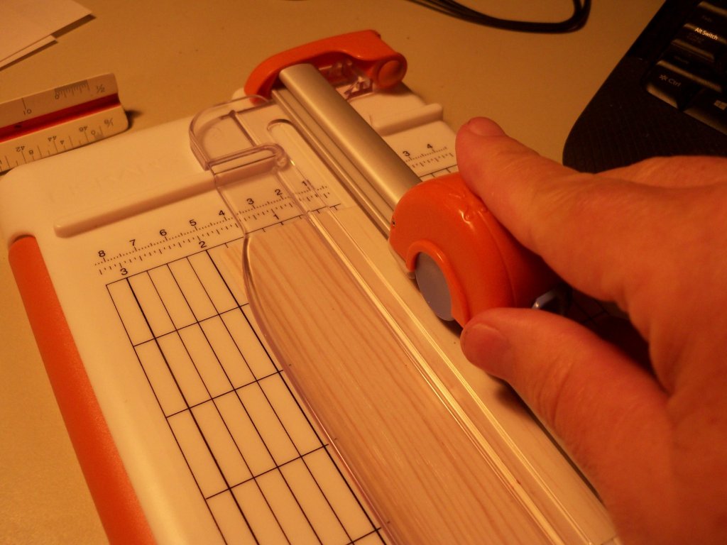
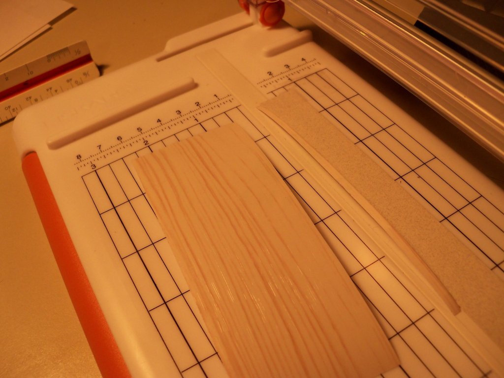
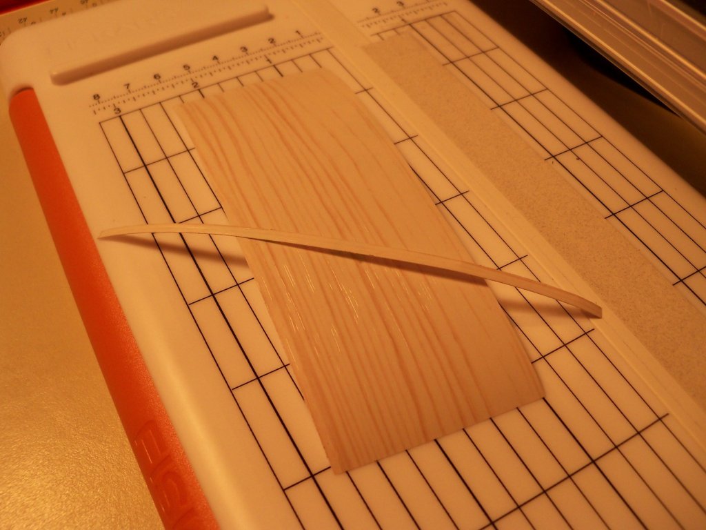
While reviewing the overall appearance of the hull, I decided to cut out the opening in the bulwarks for the cutting-in platform as I was going to display it being deployed. I used a razor saw to cut down to the covering board. Then a scalpel was used to carefully make many, many, many, (Did I mention many?) very shallow cuts along the covering board until the section could be removed without damaging the hull or the removed section that would also become part of the model. The cut was then filed and sanded smooth. Upon further review, I also thought that the rivets on the hull coppering looked way too pronounced (somewhat like a porcupine) and needed to be a little more subdued. I took a sanding block to it until I was satisfied with the new look. After reviewing the build logs of Doris and her card models, I became very interested in making use of those self-adhesive backed woodgrain strips. The bulwarks and stanchions were just semi-smooth plastic meant to be painted, but I thought that they could be improved with some wood grain and the appearance of individual planks. Since the cap rail had very little projection, whatever I used for a veneer had to be extremely thin. That pretty much eliminated any kind of wood veneer. The self-adhesive backed wood-grain strips therefore seemed to be just what the doctor ordered. I searched the web and eventually found a source that I ordered a couple of 4 inch wide rolls from. The first step was to shave off the stanchions while still leaving marks in the plastic for locating the new ones. Once again I made use of my new battery powered Dremel, some files, and a scalpel. I first used the scalpel to scribe the locations, then ground off the stanchions with the Dremel and filed it smooth. Making use of a rotary cutter made cutting narrow strips of the wood-grain tape (or as Doris refers to them as foils) easily done. First I taped a strip of heavy paper for a stop with the edge the width of the desired strips away from the cutters’ cut line. I slipped a section of wood-grain tape under the cutters’ hold down clamp until it butted up to the guide paper stop, held down the clamp, and ran the cutter over the tape. (It makes away all risk of slicing up ones fingers with the straight edge and razor method!) It makes a very smooth and precise cut. These photos below illustrate this. Once the tape strips were all cut to width, I cut them all to a scale length of 20 feet and stretched them into place. Then I went back over the strip and cut out the part of the strip where the new stanchions were to be placed and left the space bare so the AC glue could have a more secure bond with it. I used a razor blade to separate the woodgrain facing from the backing material. You just need to pull the backing partially off so you still have a bit of a handle to place the strip in position. The exposed end of the tape is pressed down on the surface to be covered. Then the tape is stretched into place gradually while peeling the backing off as you go along. (According to Doris it’s very important not to touch the adhesive with your fingers so I also used a pair of tweezers quite a bit.) Once the strip was placed, I used a strip of smooth wood to burnish it to make sure that it was securely bonded to the surface. After all the strips were in place I used an old hair dryer to apply a little heat which also helps to promote a better bond. Where openings were encountered, I just went right over them and returned to them later with a fine file to open them up. Here are a few photos of the taping process to this point. Next I applied a watered down application of white acrylic paint over the tape. I cut a strip of 1/32” thick maple that was cut to match the width of the removed stanchions. It was sanded and given 3 coats of the watered down white paint on the edges and one face with sanding after each coat. This strip was then cut to the length of the stanchions from the covering board up to the bottom of the pin rail and glued in place with some AC as shown below. I have now almost caught up to the actual build. Seems like it takes longer to write up the log than it takes to actually build the model.


- 107 replies
-
- 11
-
-
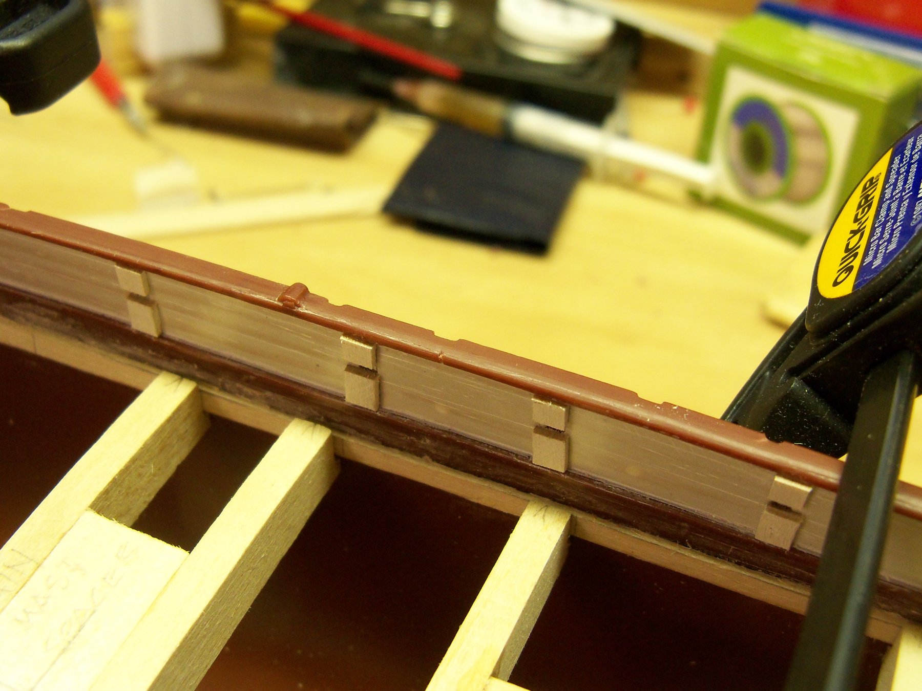
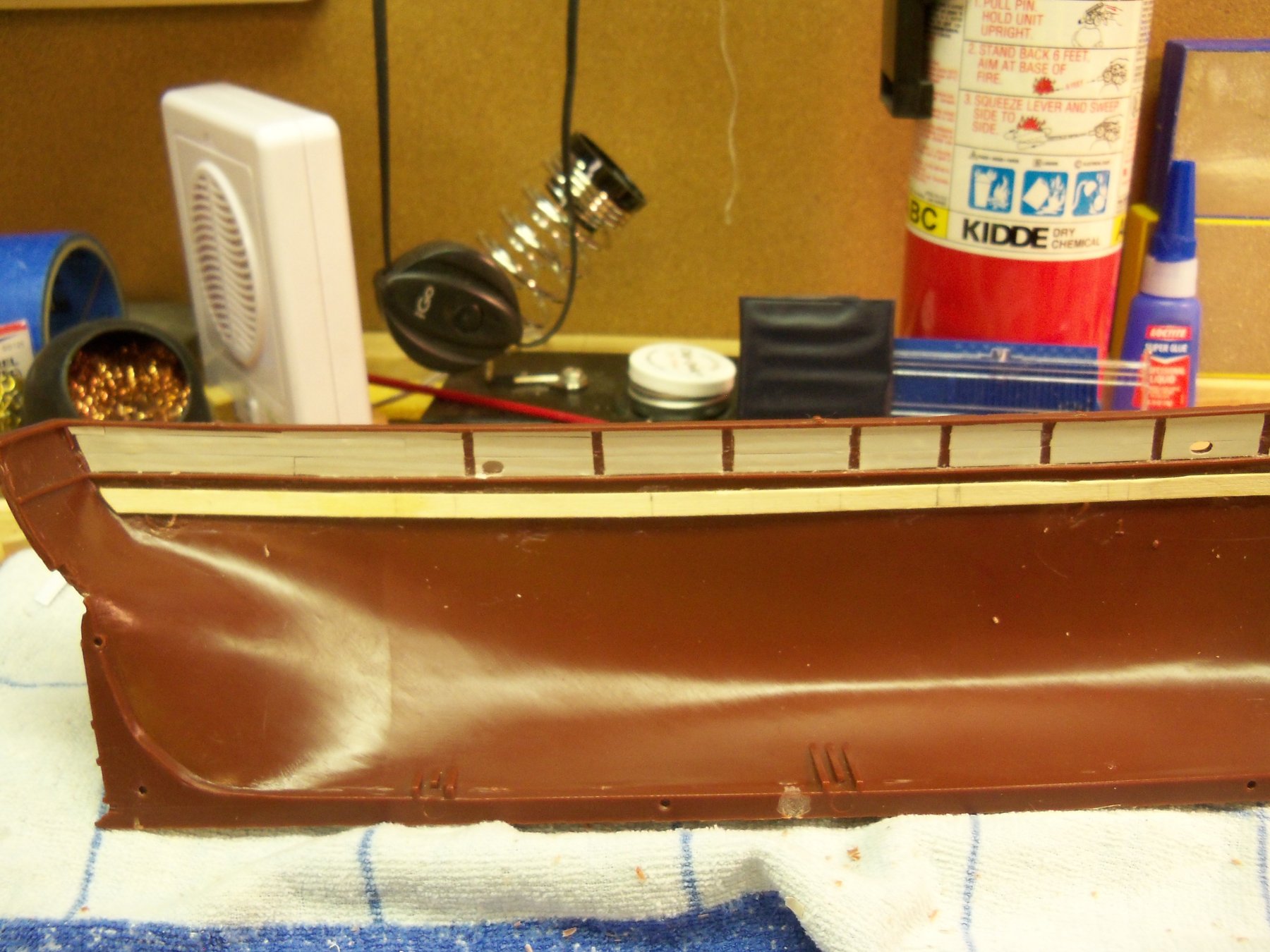
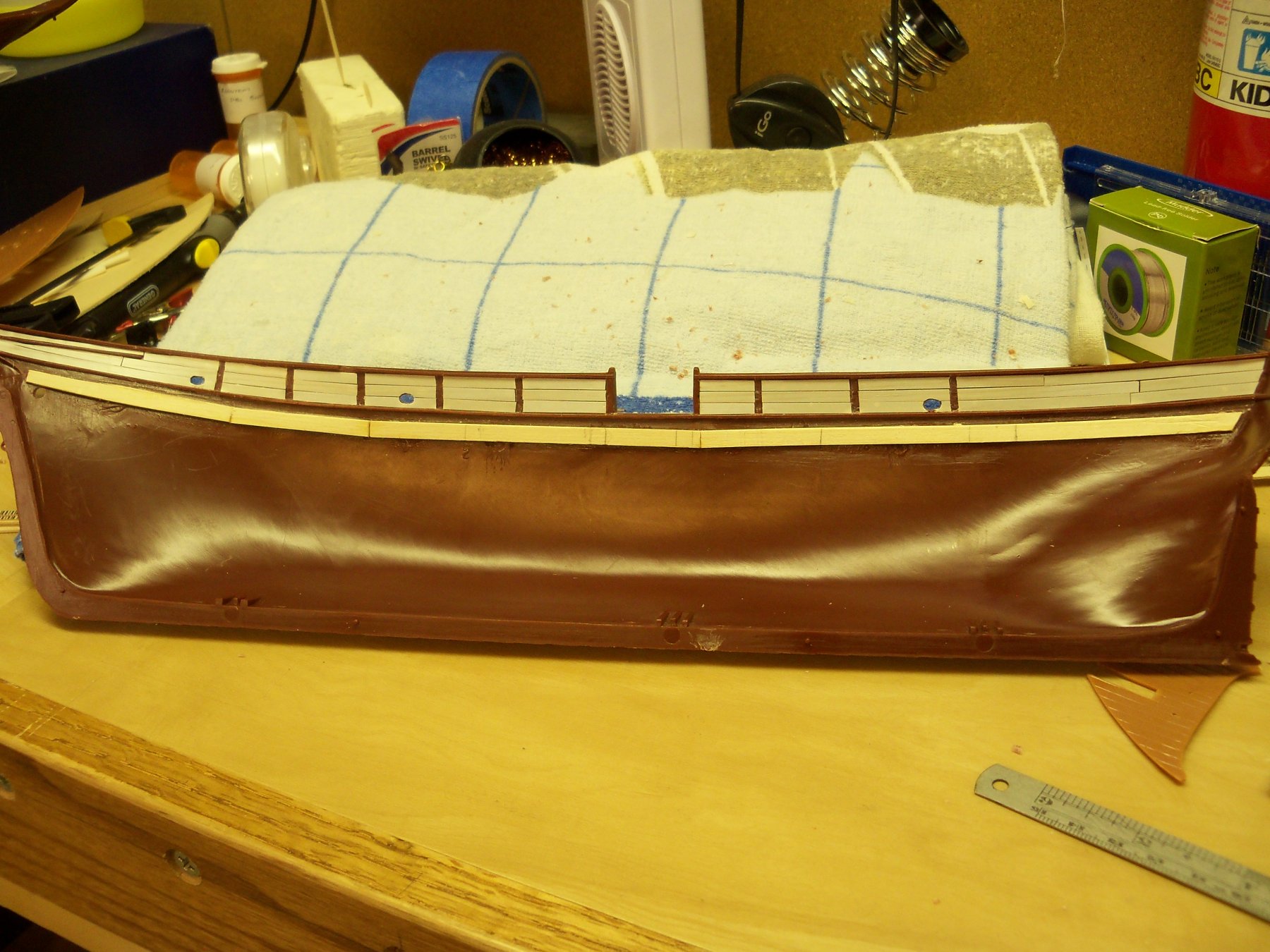
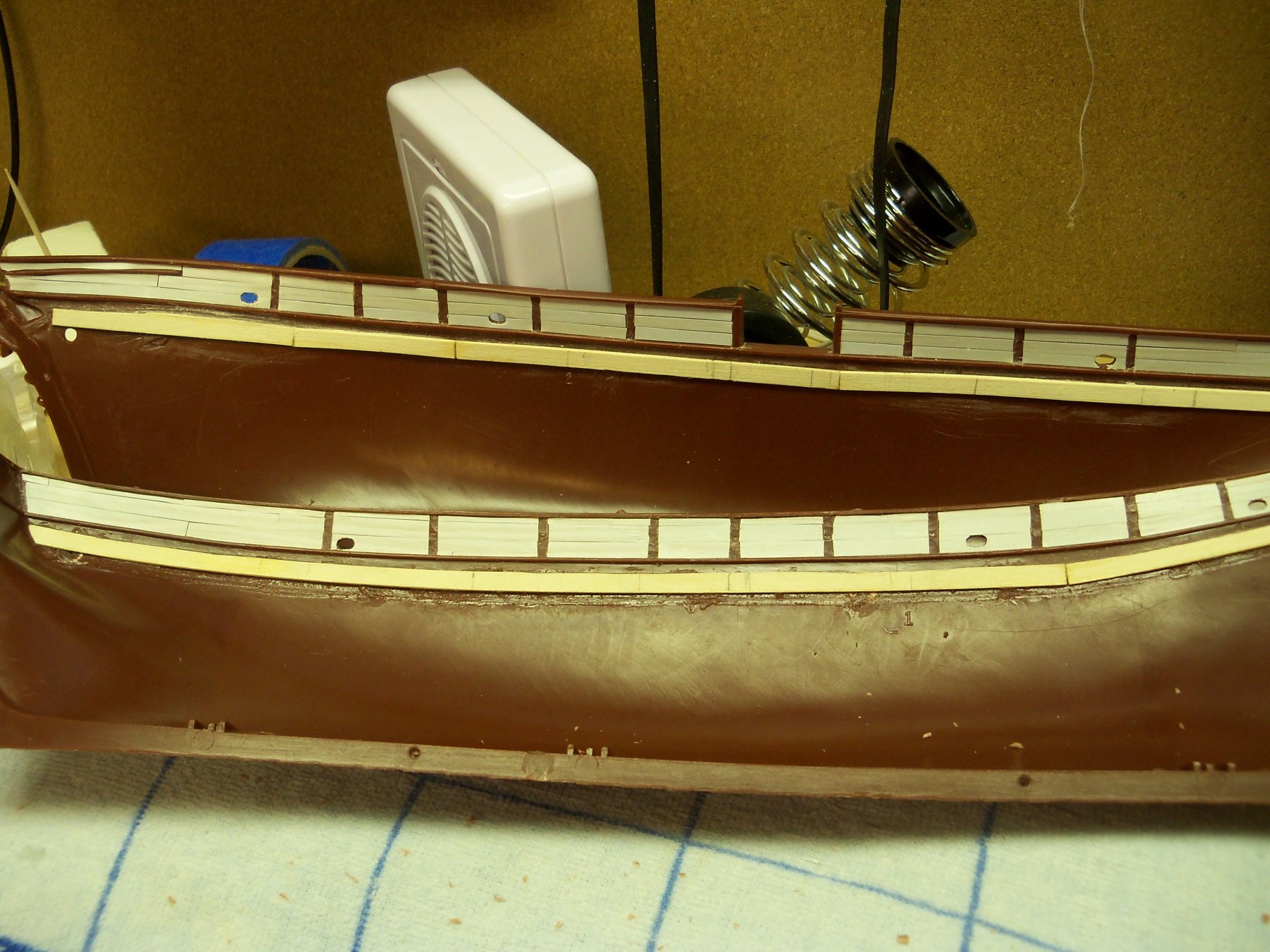
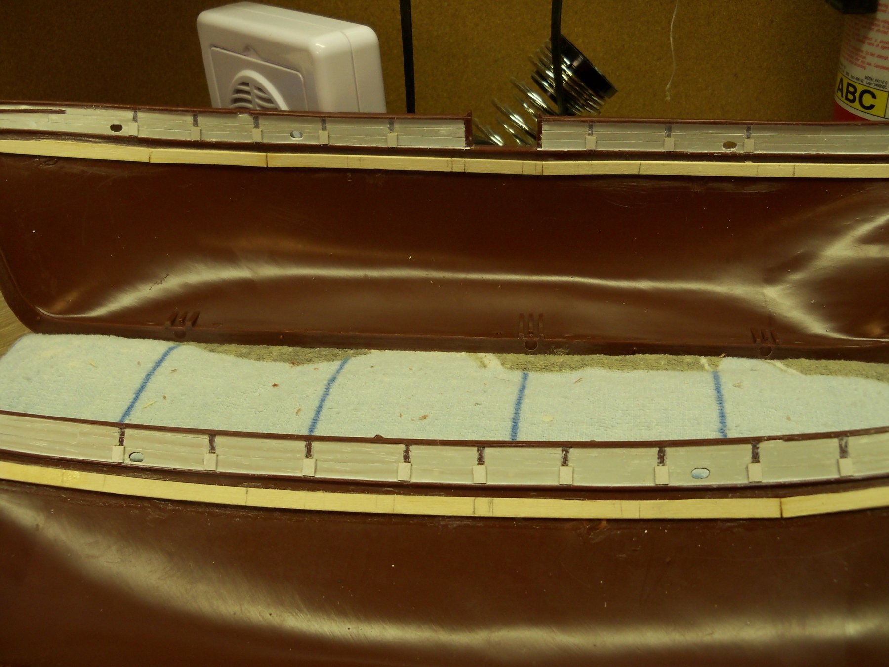
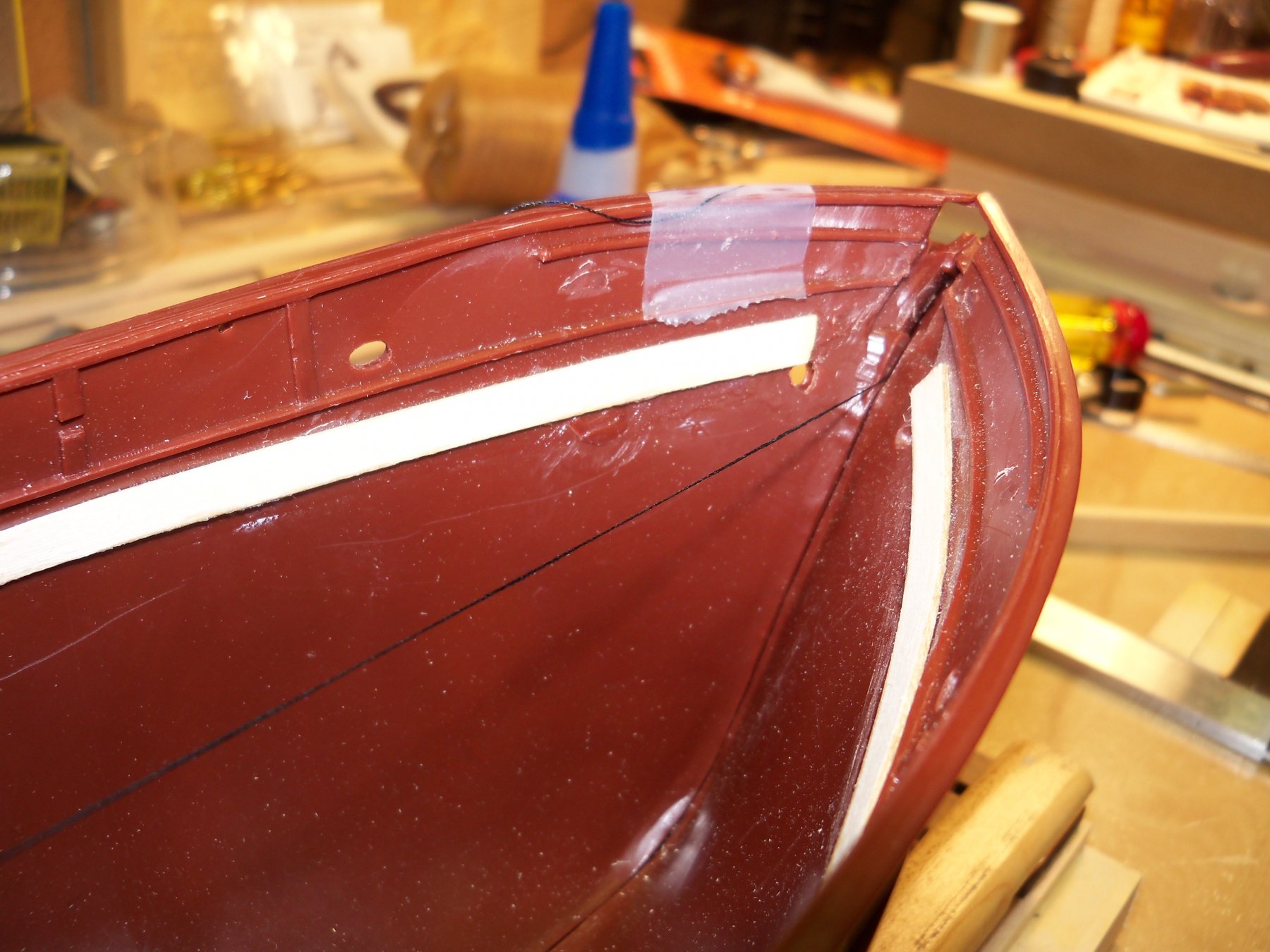
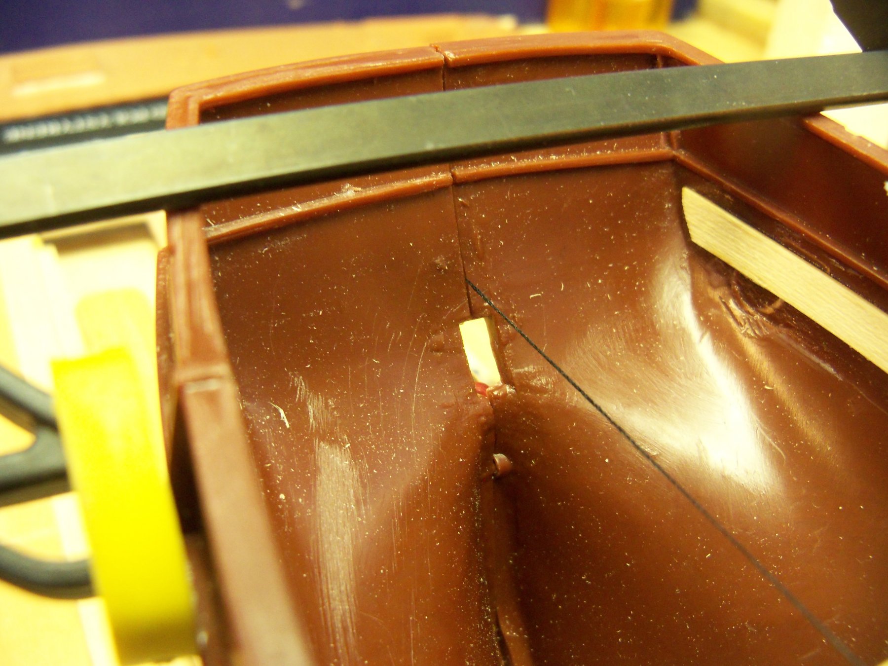
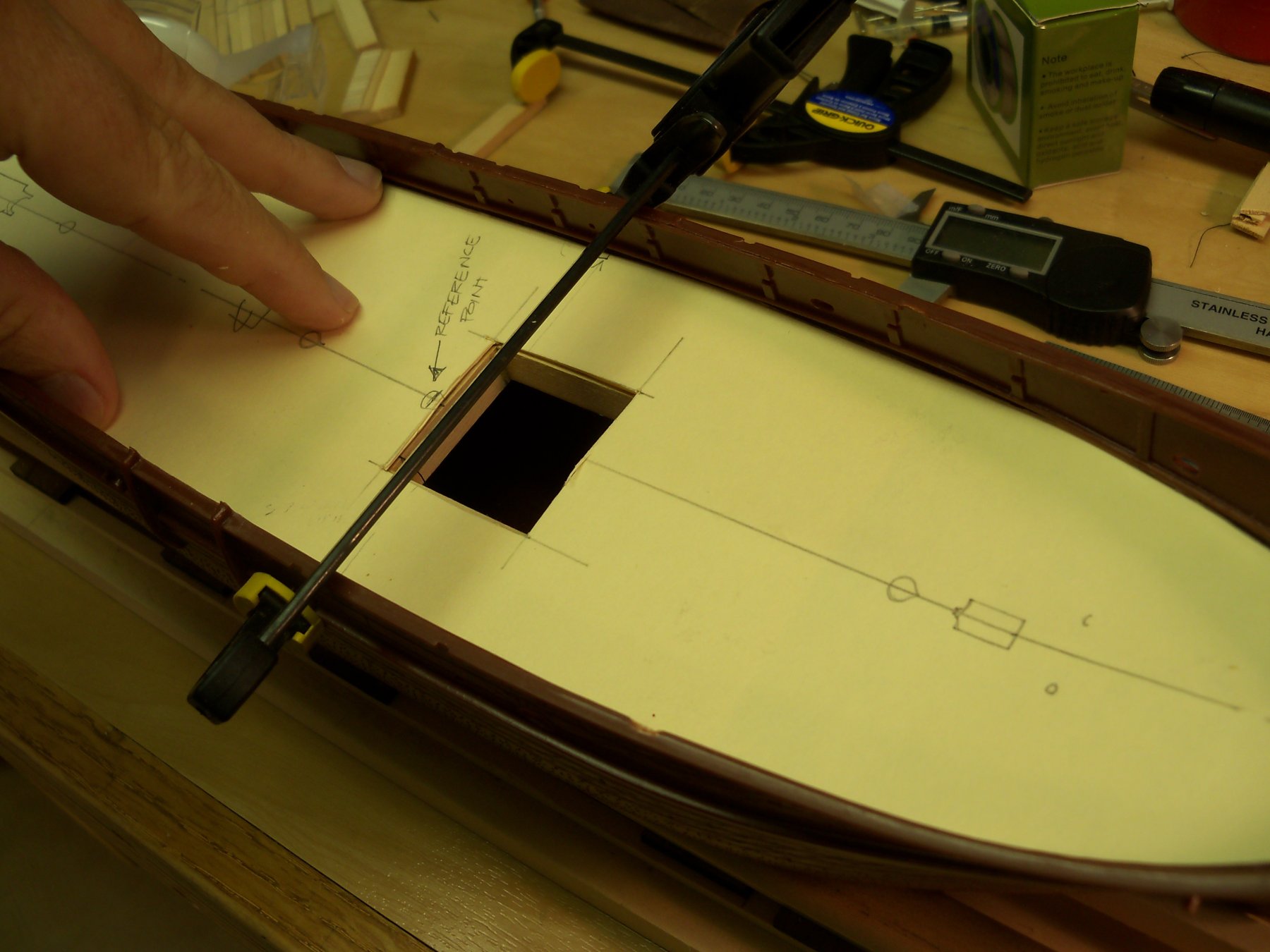
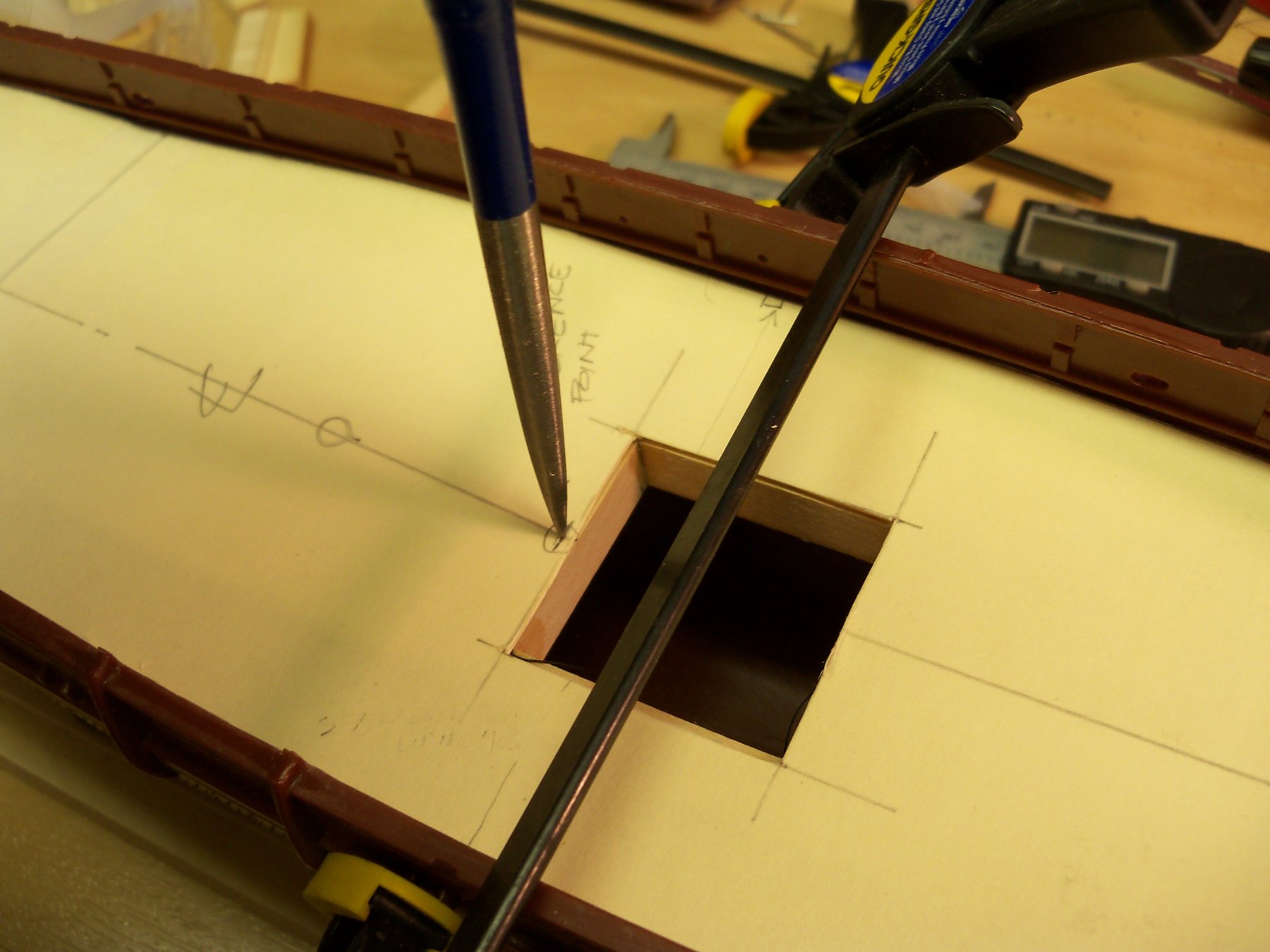
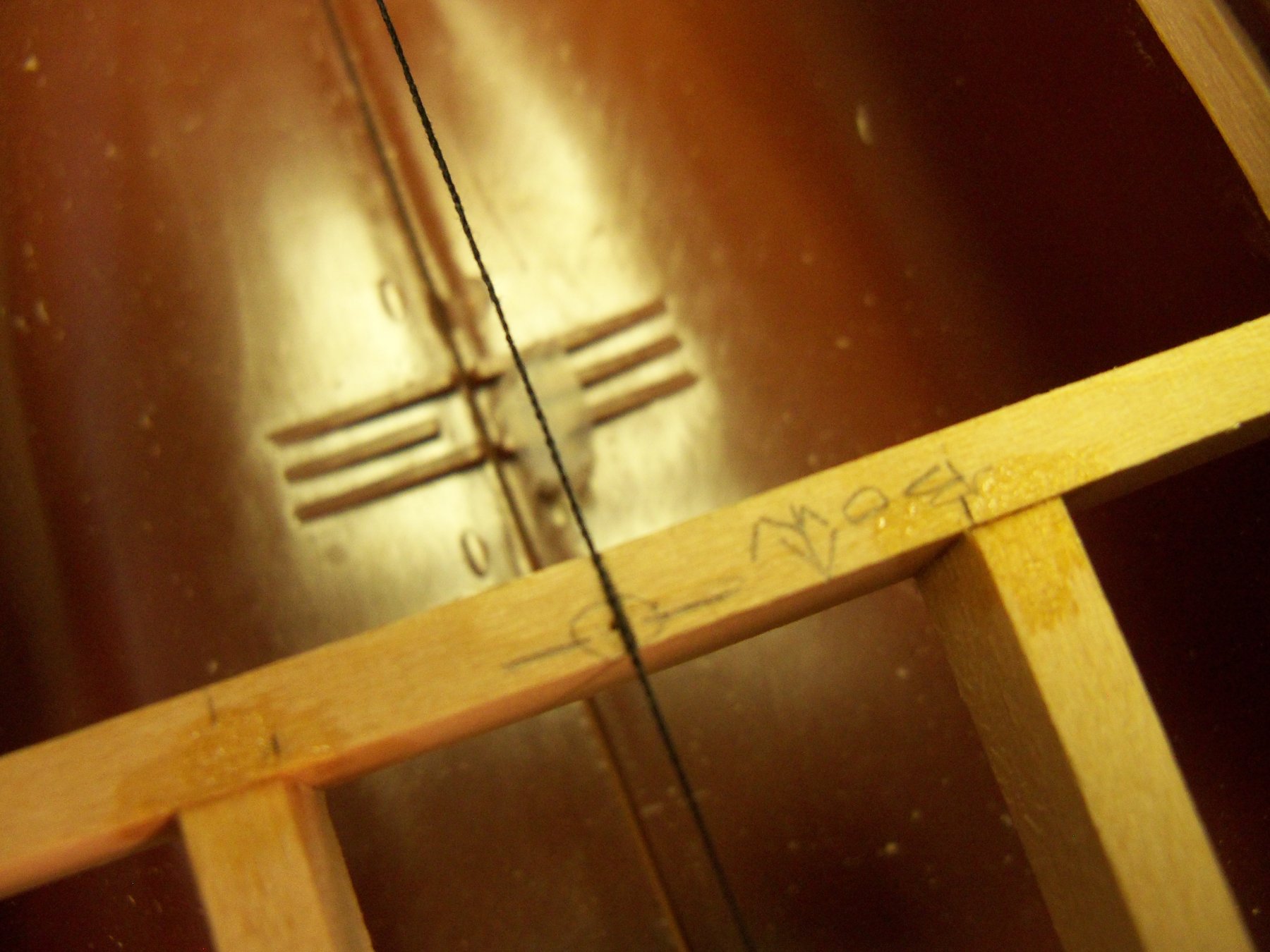
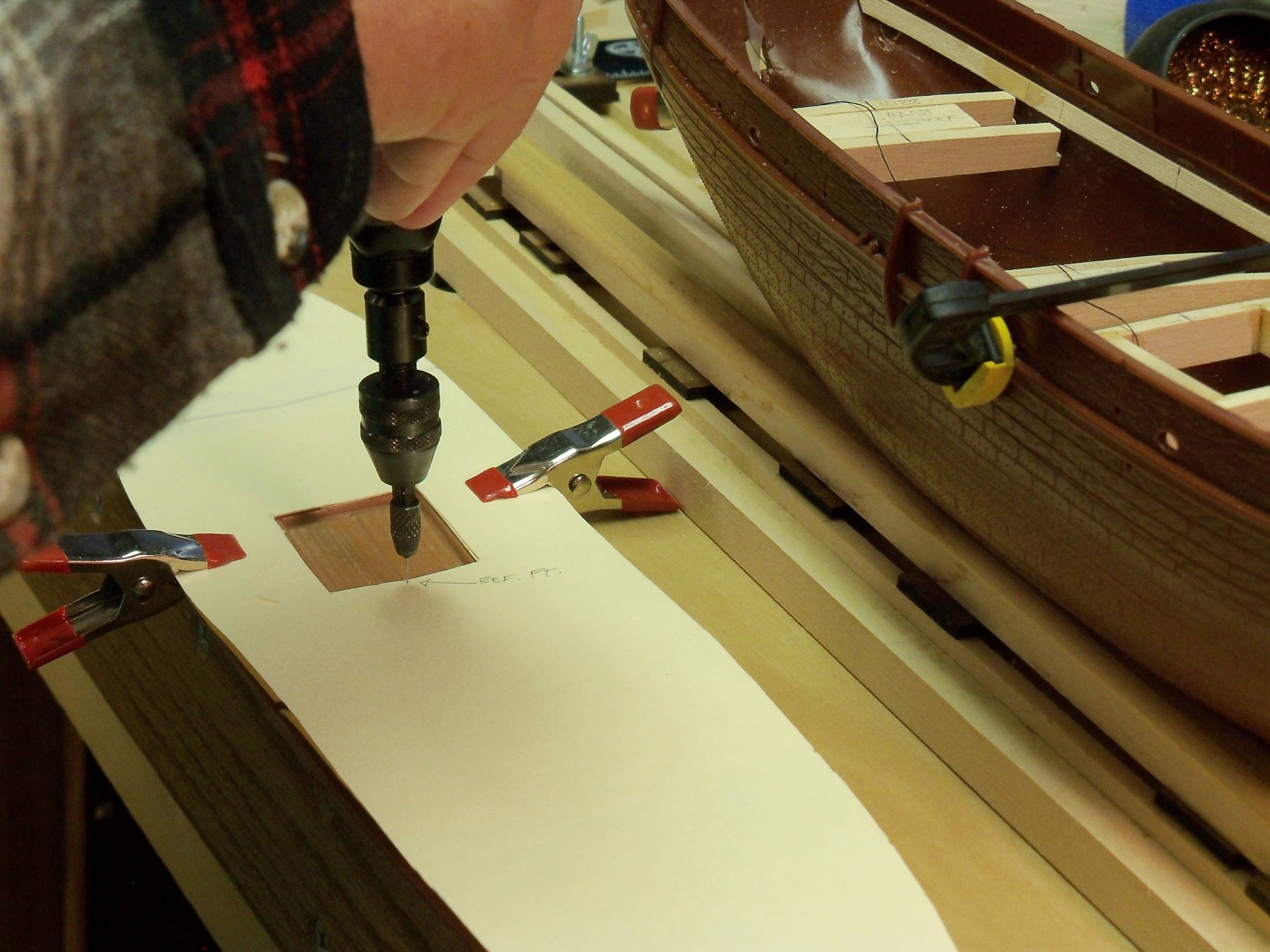
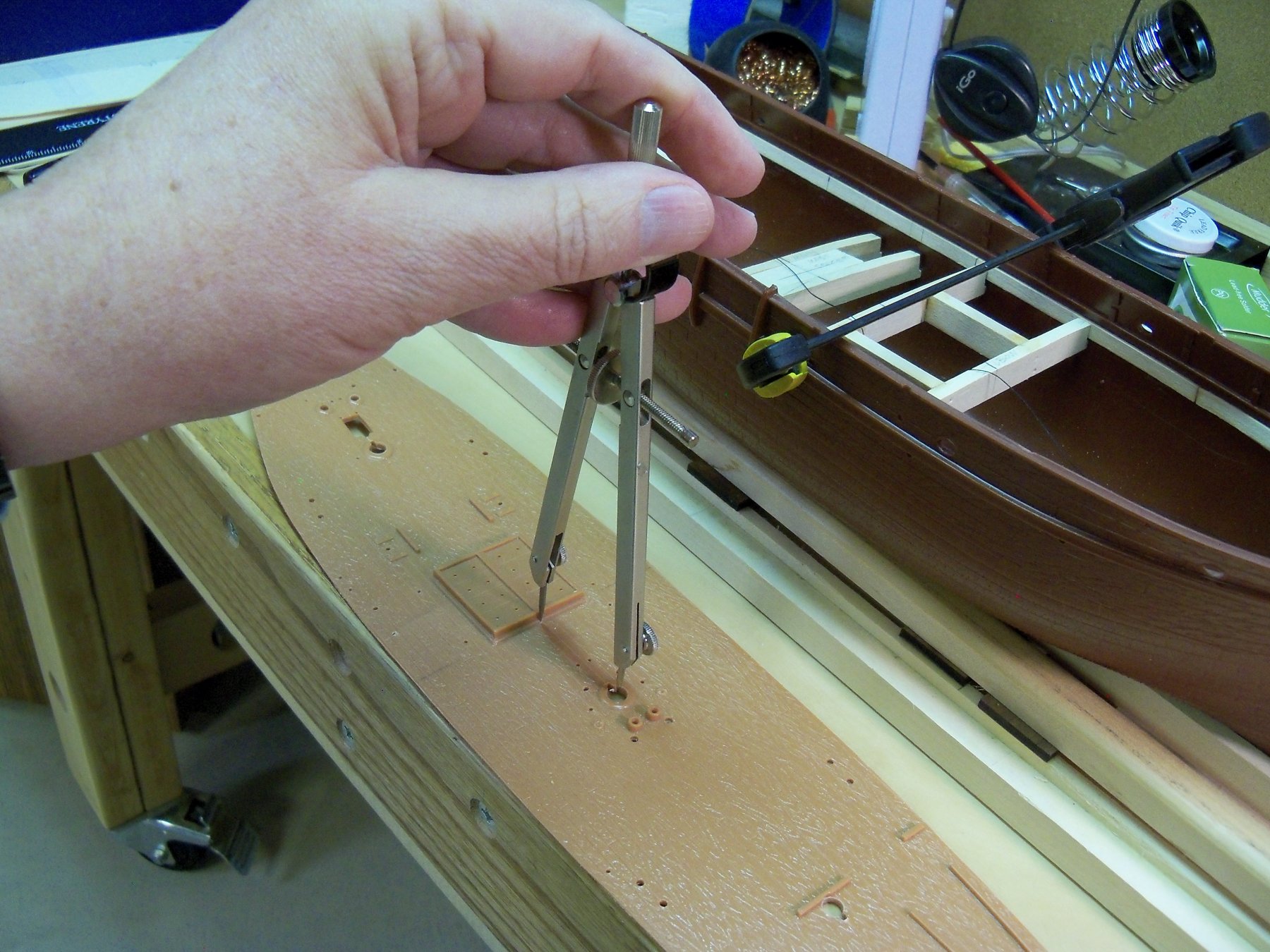
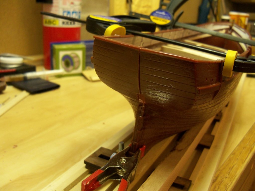
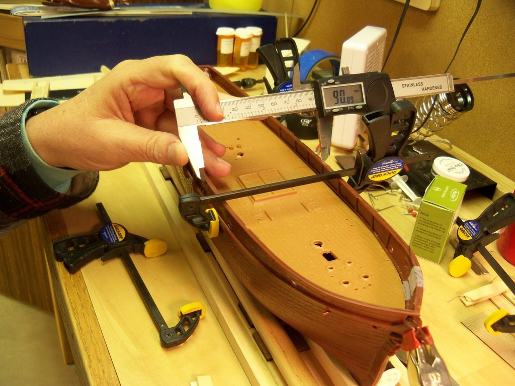
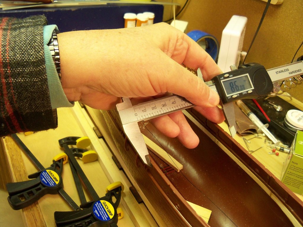
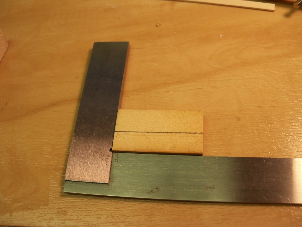
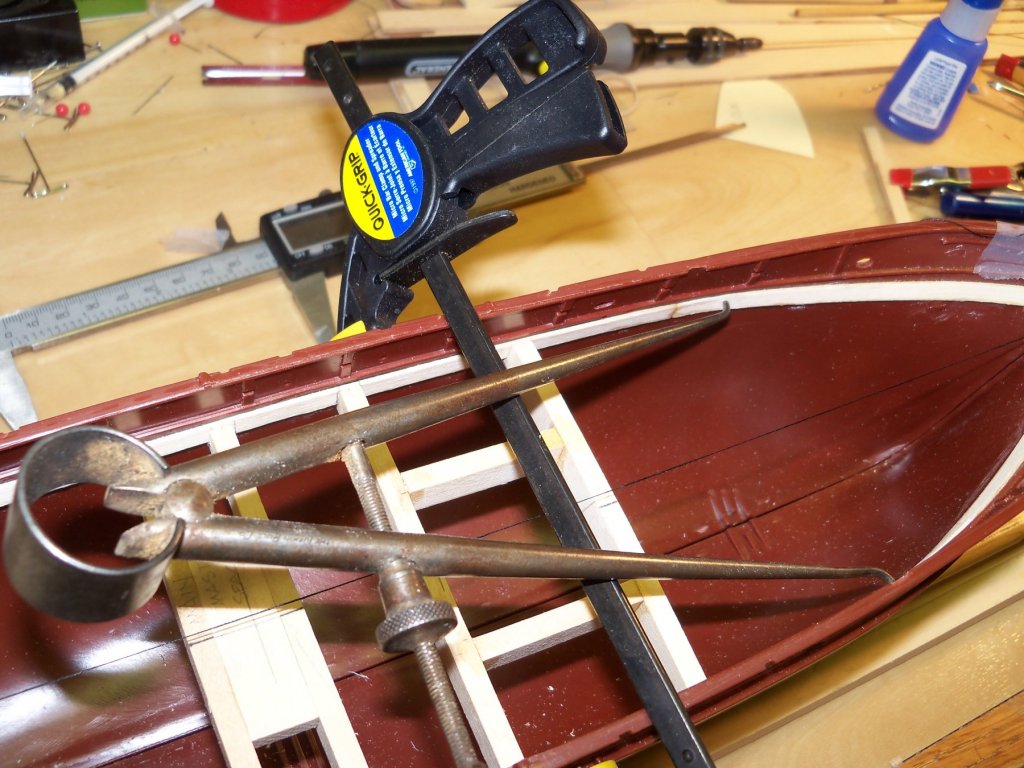
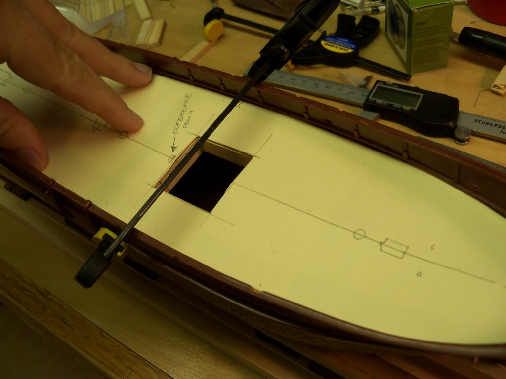
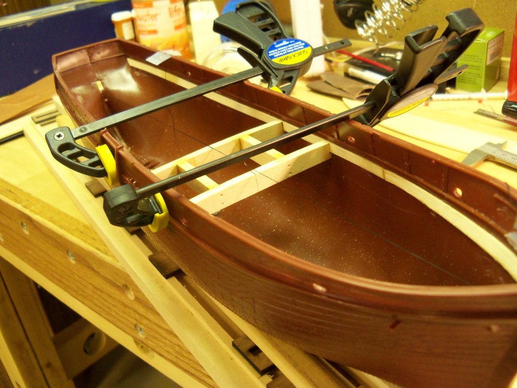
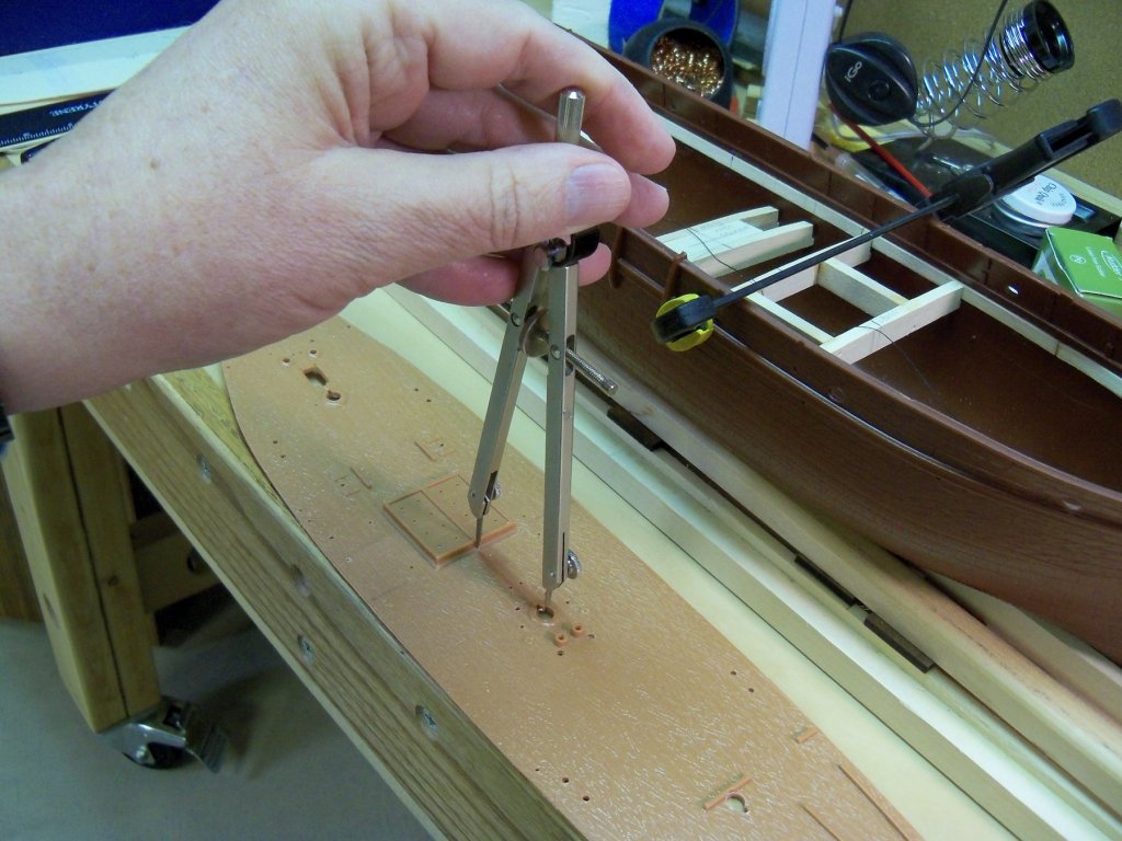
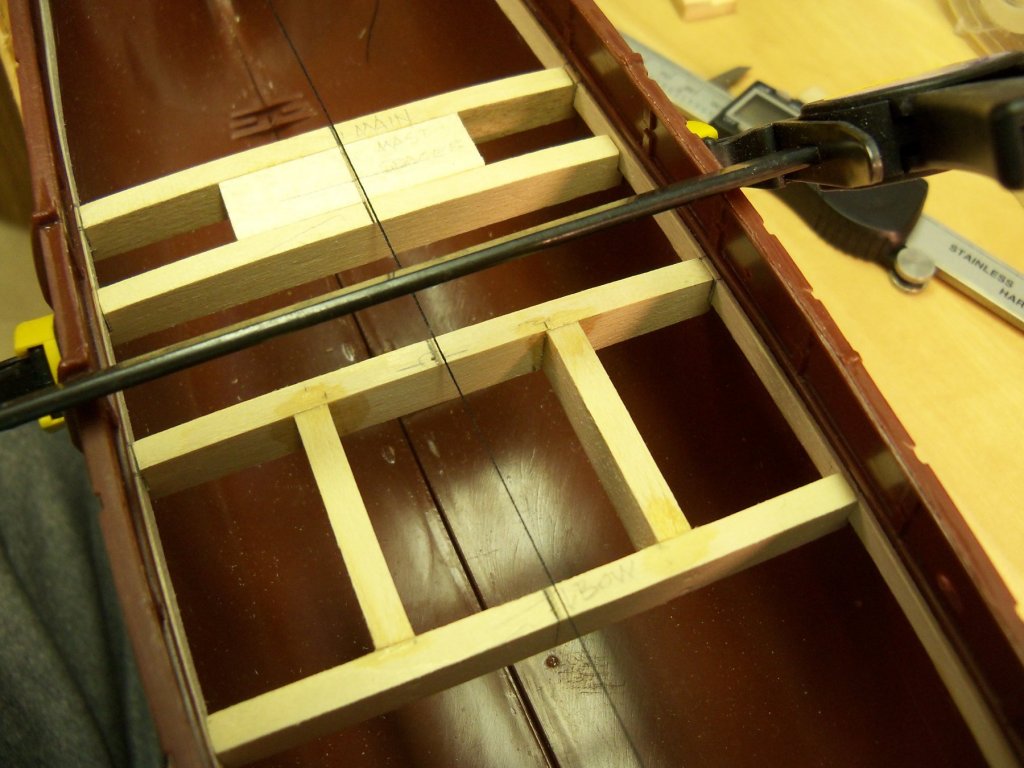
Getting back to my log once again, I decided to try a trial fit of the hull. When I clamped the two hull halves together, I dry fit the plastic deck in place to see how things lined up. Unfortunately they were a poor fit and had to be forced together with clamps. Once they were together however, I thought that it was a problem that I could work around. Measuring the width of the hull (90.89 mm) once assembled, I made note of it and then measured it again (86.88 mm) with the deck removed. As you can see above, without the deck in place it turned out to be quite a bit less. Obviously one or both of the hull sides warped inward and needed to be held in place at the 90.89 mm measurement. So, knowing that I needed some kind of reference line to use that didn’t involve measuring from the sides, I decided that the best bet would be to establish a centerline to aid in placing the deck beams. That way I knew that as long as I kept the beams perpendicular to that line I could be assured that my location measurements for all of the other beams would line up with the locations of all the mast holes and the hatch opening would be square. To help me to set things perpendicularly, I made up a small (it had to be to fit inside the hull) wood square with a perpendicular line drawn on its face as shown below. To set up this center-line I took a length of black thread and ran it through the hull seams at the bow and stern, stretched tight and taped in place. (As the shear of the deck was quite pronounced, the thread could be shifted up or down as needed to allow the line to be above the beams.) Then the hull halves were clamped back together again. The first beam had to be carefully measured for length so that when set in place it would not distort the hull beyond the 95 mm measurement. By the way, all of the measurements for the length of the beams were done “old school” with a pair of inside calipers that I inherited from my grandfather. The first beam was placed at the approximate location of the rear of the hatch opening perpendicular to the center-line. A clamp was set across the hull to hold the beam in place. The hatch opening was cut out of the manila template and I slipped it back into place. It took a few adjustments until I was able to get the beam where it belonged, but once the beam was correctly in place, I took an awl and punched a hole through the template into the beam to set up a reference point to make all further beam placement measurements from. The template was then removed and I put locating marks on the faces of the ledgers for that first beam. The first beam was used to locate the forward edge beam of the hatch, which was cut and put into place. The space between them was measured and then both beams were taken out, the cross beams were cut to length and the framing for the hatchway was assembled with glue and pins. I took this assembly and clamped it in place once again inside the hull. The locating hole on top of the first beam was then marked and labeled as shown below. The template was lined up with the backside of the plastic deck and a hole was drilled thru the deck that now would line up with the hole previously made in the first hatch beam. Now when an items’ location was needed, a set of dividers would locate it on the plastic deck and be transferred to the location of the same item on the deck of the model. Now I needed to place a pair of beams with a spacer block for all three masts. Working on the main mast first, I used my dividers to locate the rear beam, measured the space, and cut the beam to fit. Then the spacer was centered and glued to the forward face of that beam. The other beam was then measured, cut, and also glued to the spacer as shown below. This mast beam assembly was then marked on the ledgers, and then this procedure was repeated for the mizzen and the fore mast. I changed my ideas on how to do the bulwarks and stanchions, so now I will be making a few more revisions to my build once I order some special products to do them with. More to follow.


- 107 replies
-
- 11
-
-
I guess that I would second that assessment! Of course that was just another opportunity to use some more of that innovative problem solving that you are so good at. That is something that we have in common and it's one of my favorite things about modeling.
- 1,306 replies
-
- 4
-
-
- syren
- model shipways
- (and 1 more)
-
Personally, I heartily agree with that, as power chords are the bane of people in wheelchairs! I find them constantly in the way. I am either rolling over the chord or getting it tangled in the chair itself. I also use that Dremel drill and really like using it for just that reason.
-
I am currently researching methods of making sails from paper (since any cloth would be much to heavy for this small scale) for my 1:96 MS Phantom. To date I have experimented with several different methods, but am not entirely satisfied with the results. As I was looking at your "harbor", I realized that quite a few of your ships have sails. Since I assume that you make your sails with some type of paper and that you are a very skilled at modeler in this medium, I wondered if you have any info available for the method that you use.
- 1,035 replies
-
- 6
-
-
- royal katherine
- ship of the line
- (and 1 more)
-
As intricate as your models are, and the fact that you have so many of them, how do you manage to keep them all from collecting dust? Is this room off limits from your feathered friends? (We only have one bird and he can put out a lot of dander, especially when he is molting .)
- 1,035 replies
-
- 5
-
-
- royal katherine
- ship of the line
- (and 1 more)
-
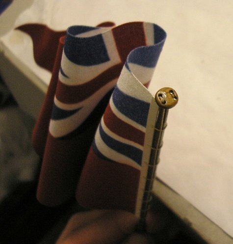
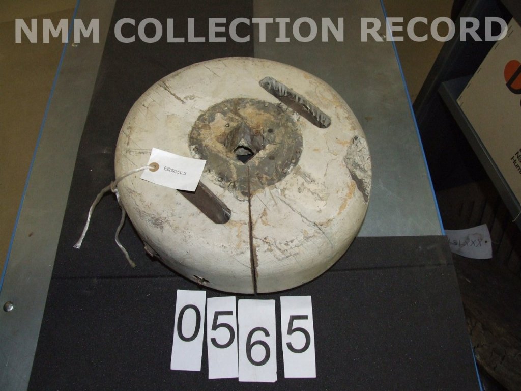
While searching for info on the masts for my 1:96 MS Phantom build, specifically the mast trucks, I came across this mast truck in an antique shop shown below that gave me some idea of its construction. While searching further I found this picture in Doris's Royal Caroline build. I made this comment in her current build of the Royal Katherine: "You really pay attention to the smallest details, as can be seen by the flag at the stern of the Royal Caroline where you even detailed the truck on the flag pole. Now, that is one detail that I have very seldom seen realistically addressed in such a small scale!" After seeing this photo, I thought that I should be able to make something similar for the upper masts on my build. I haven't made anything in clay yet, but after seeing her version I'll give it a try. (I'm assuming that hers was made from clay)
-
Tiger Tank 334 by torpedochief - 1/16 - Radio Control
BETAQDAVE replied to torpedochief's topic in Completed non-ship models
My father came across one of these on the side of a road, while in France in WWII. He told me that there didn't seem to be any visible damage to it other than the track being blown off. While he was with a mobile anti-aircraft artillery company and never saw one in action, he said he couldn't imagine being one of our tank crews trying to face one of these monsters while inside our own under armed and thinner armored Sherman tanks. He talked to some some guys who did just that, telling him that their 75 mm shells just seemed to bounce off of them, while the Panzers' 88's just ripped right thru ours. They would try to disable them by going for the tracks, but even having done that, they were still facing an armored artillery piece that was still capable of taking out just about anything we could throw at them! Until we started getting more of our newer Patton tanks into the war to level the playing field somewhat, we were really taking a beating. Lucky for us the number of these tanks in the field at that time was limited. While it may be true that they were some of the most formidable weapons of their time, lets never forget all of our servicemen who were killed and wounded facing monsters like this just to make the life we lead now even possible! -
Was looking back at your Royal Caroline build log and can see that your current build is just more of the same exquisite workmanship! You really pay attention to the smallest details, as can be seen by the flag at the stern of the Royal Caroline where you even detailed the truck of the flag pole. Now, that is one detail that I have very seldom seen addressed in such a small scale! I showed the video at the end of that build to my wife (who seems to think I'm kind of nuts to put in all the small details that I try to incorporate into my ships) and she was astonished to see the level of detail that you included. She was particularly impressed by all of the interior details down to the paintings on the walls and the watermelon slices on the table! I still have a hard time believing that these are built with card stock! Anyone should be able to see now that this build of the Katherine is just a continuation of your skills that frankly tell me that your ships deserve to be in a museum!
- 1,035 replies
-
- 8
-
-
- royal katherine
- ship of the line
- (and 1 more)
-
ROYAL CAROLINE 1749 by Doris - 1:40 - CARD
BETAQDAVE replied to DORIS's topic in - Build logs for subjects built 1501 - 1750
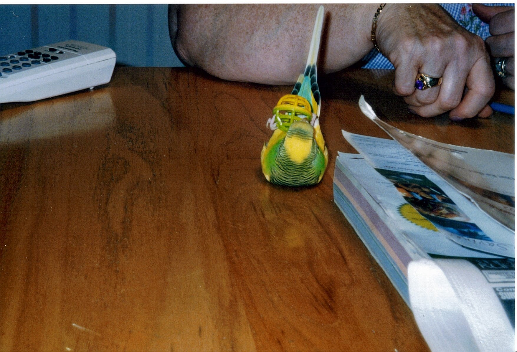
I was just reviewing the Royal Caroline build log and came across the picture of the parrot on its back and the ensuing comment and thought I could maybe add some insight as to the birds' peculiar behavior. We had a parakeet awhile ago who would do the same thing but was generally just looking for some attention or wanted to play. Here he is with his favorite toy. He could spin it around, throw it away, chase it down and repeat several times. (Maybe he was in a circus in a previous life?)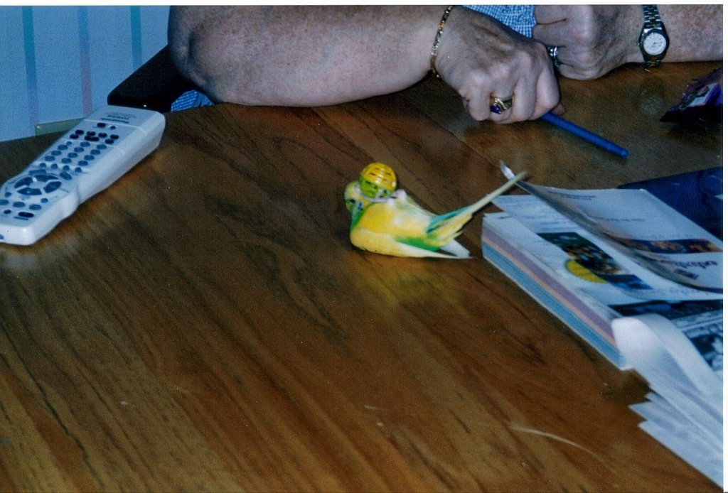

- 883 replies
-
- 6
-
-
- royal caroline
- ship of the line
- (and 1 more)
-
I think your first order of business would be to look up the Endeavor in the build logs for Ship Model Kits and open the quick-find indexes. There you will even find a couple listings for the kit by Constructo. Good luck with your first wood build, as this will be a totally different experience than plastic kits.
-
Syren rigging hooks
BETAQDAVE replied to BETAQDAVE's topic in Metal Work, Soldering and Metal Fittings
How were you able to drill the holes without twisting or tearing up the hook or having it rotate out of the sheet? Did you back up the sheet with anything in particular? -
Antonio, I agree with Frankie on this solution as I had to do it the same way.