BETAQDAVE
-
Posts
5,386 -
Joined
-
Last visited
Content Type
Profiles
Forums
Gallery
Events
Everything posted by BETAQDAVE
-
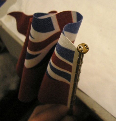
Here is a photo of a full size mast head truck. Here is a photo of a flag truck from one of Doris's card models.

-

Dremel rotary tool - which one?
BETAQDAVE replied to RPaul's topic in Modeling tools and Workshop Equipment
I would have to agree on that. All of my accessories like the drill press and router attachments use the corded versions as the chord isn't such a hassle, but for everything else, the 8050 is the way to go for me. (Chords and wheelchairs don't go well together!) Also, I remember all of those Timex commercials on our Black and White TV! Makes you feel old doesn't it? -
MONTAÑES by Amalio
BETAQDAVE replied to Amalio's topic in - Build logs for subjects built 1751 - 1800
Aside from the superb precision of your wood joinery and components (more like a fine piece of furniture), I find the fact that your rigging here is so well done that it is worth a separate mention of note. Your lines are more like what one would expect to see in full sized rope as they have an incredibly realistic drape to them, as if they have real heft to them rather than looking like the fine thread found in most models that have essentially no real weight to them! If one didn't know that this was just a model, you could almost swear that this is a photo of a full size replica! -
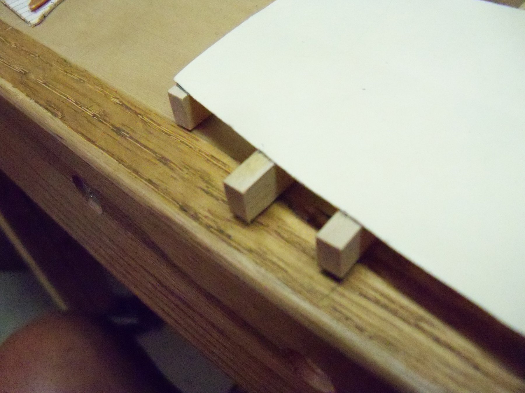
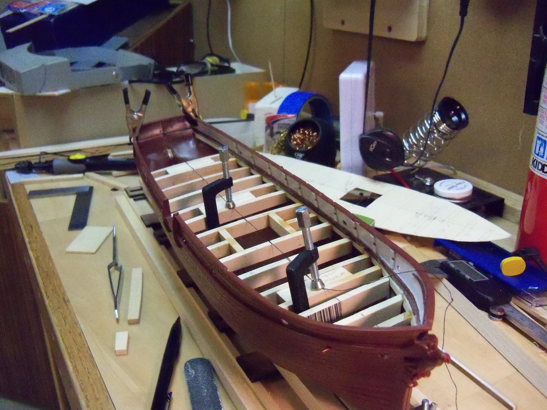
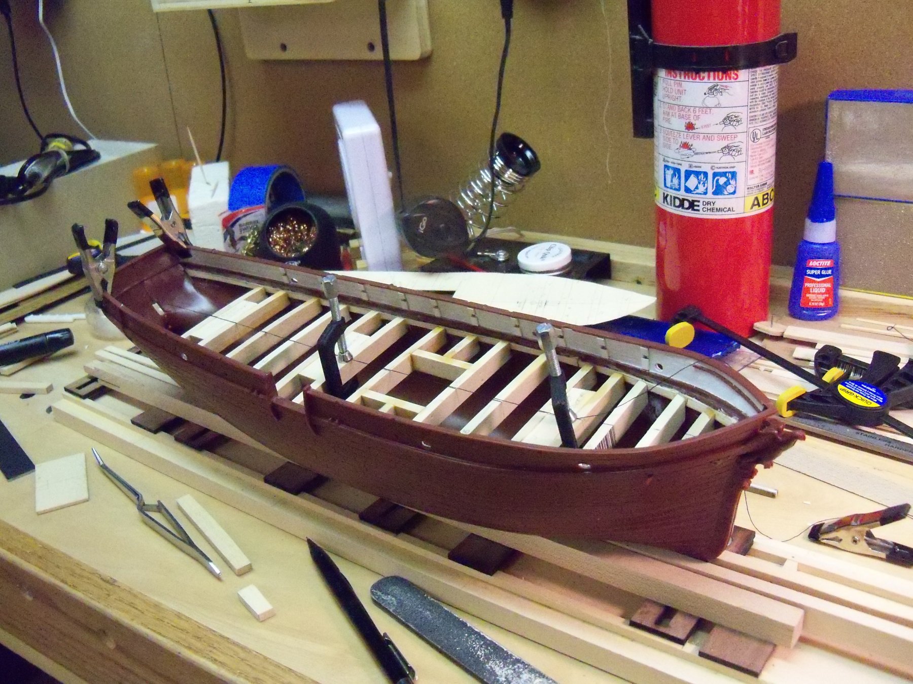
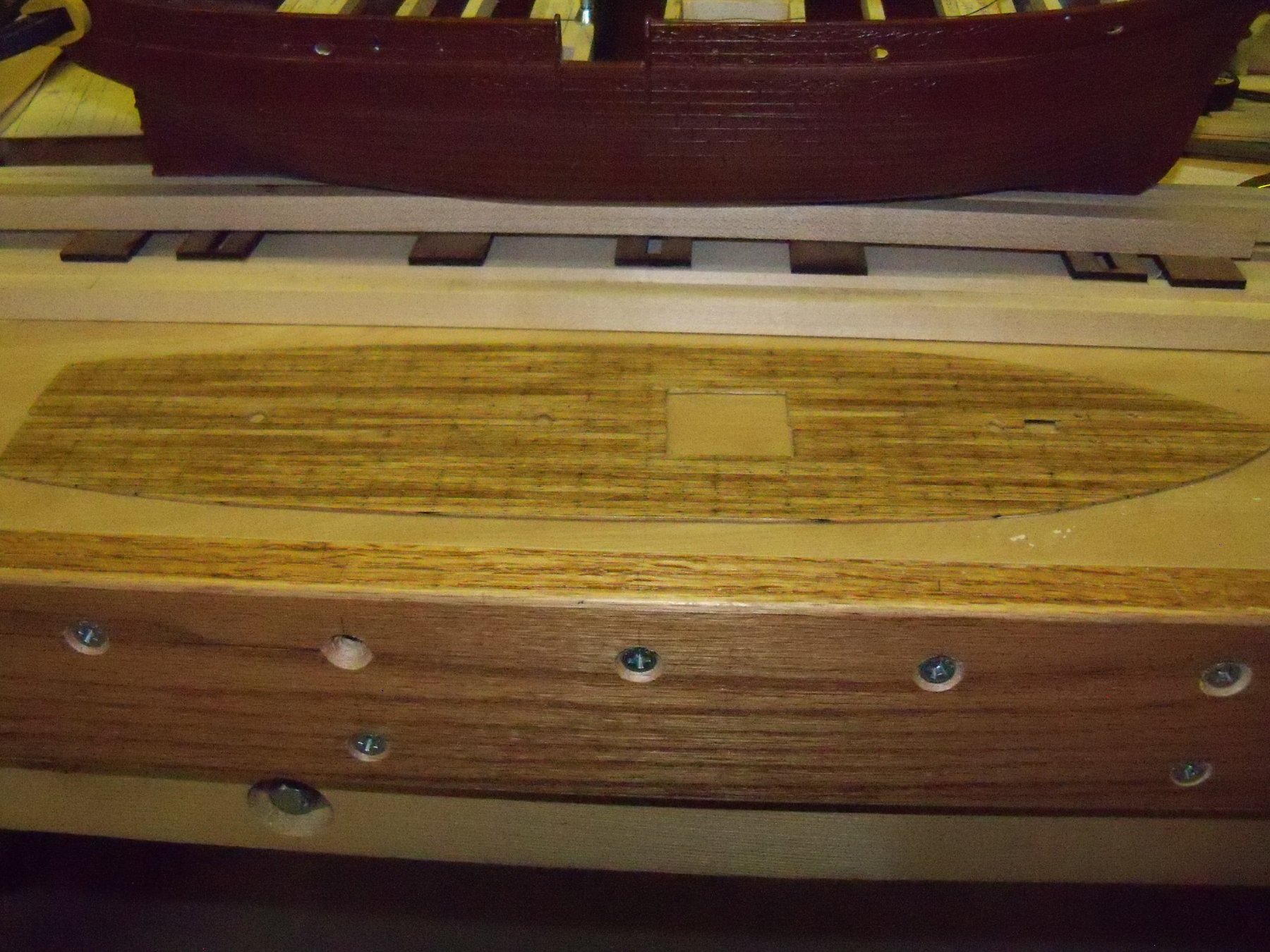
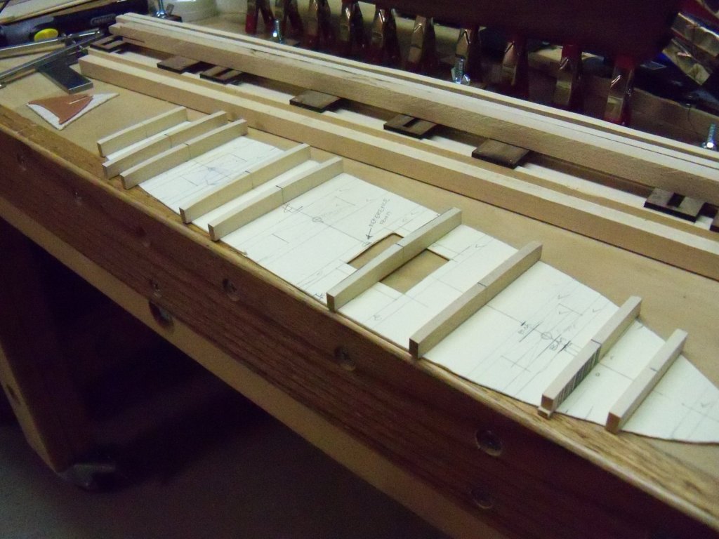
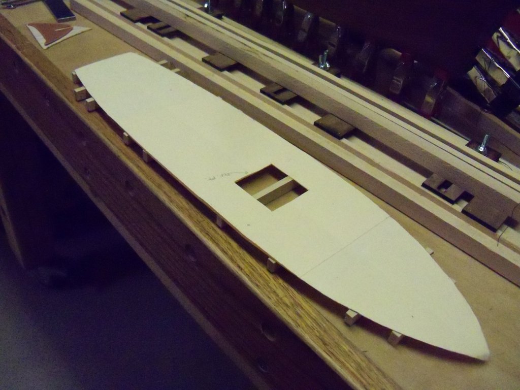
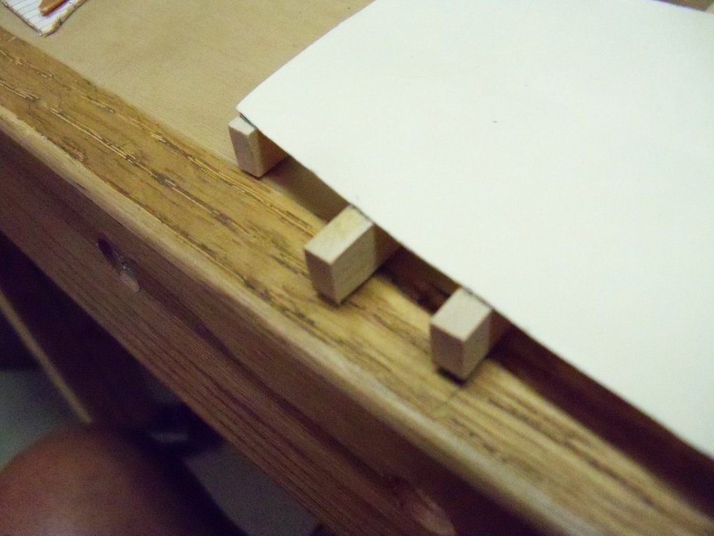
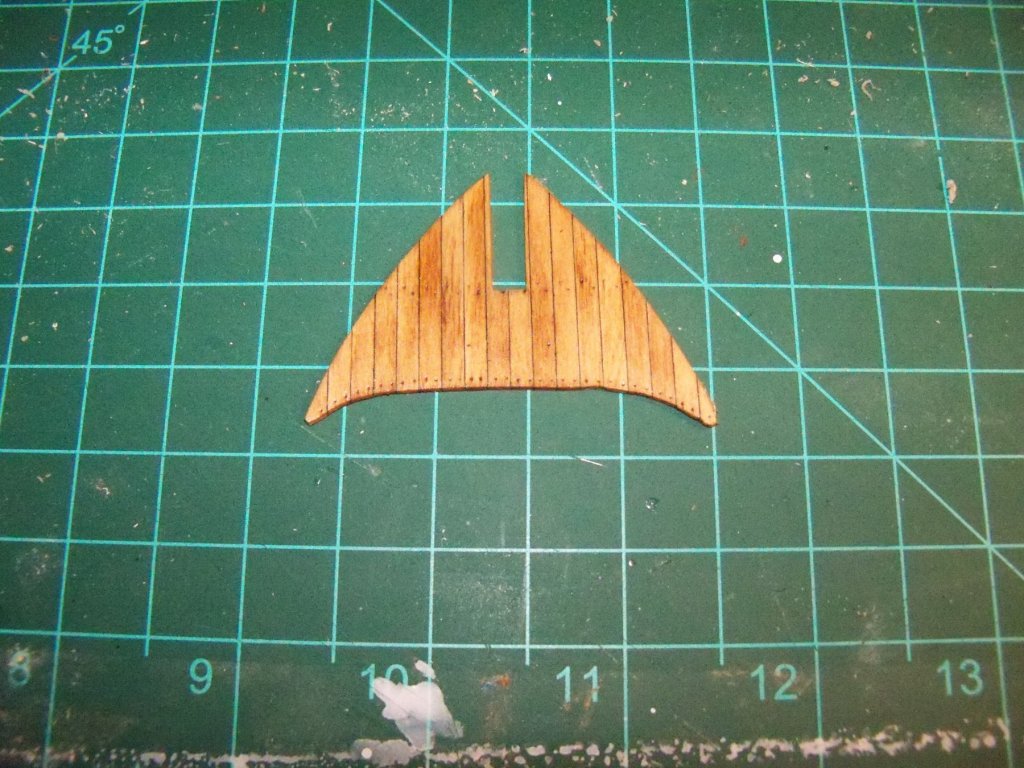
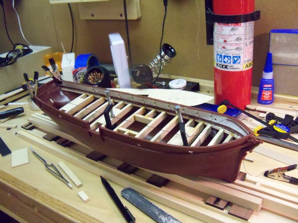
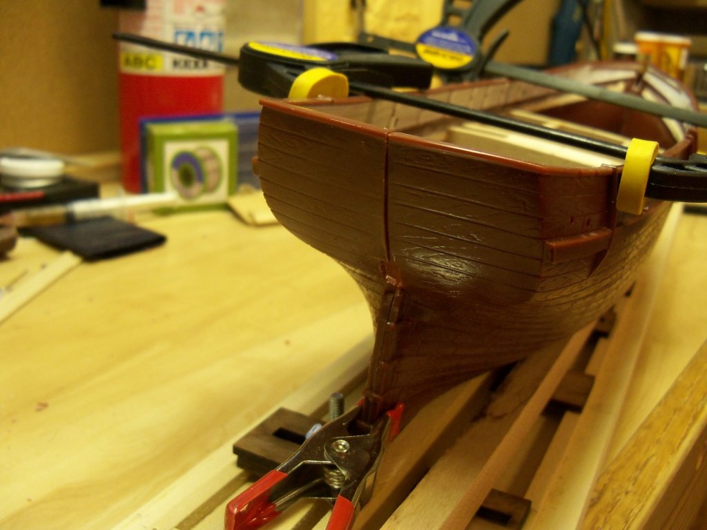
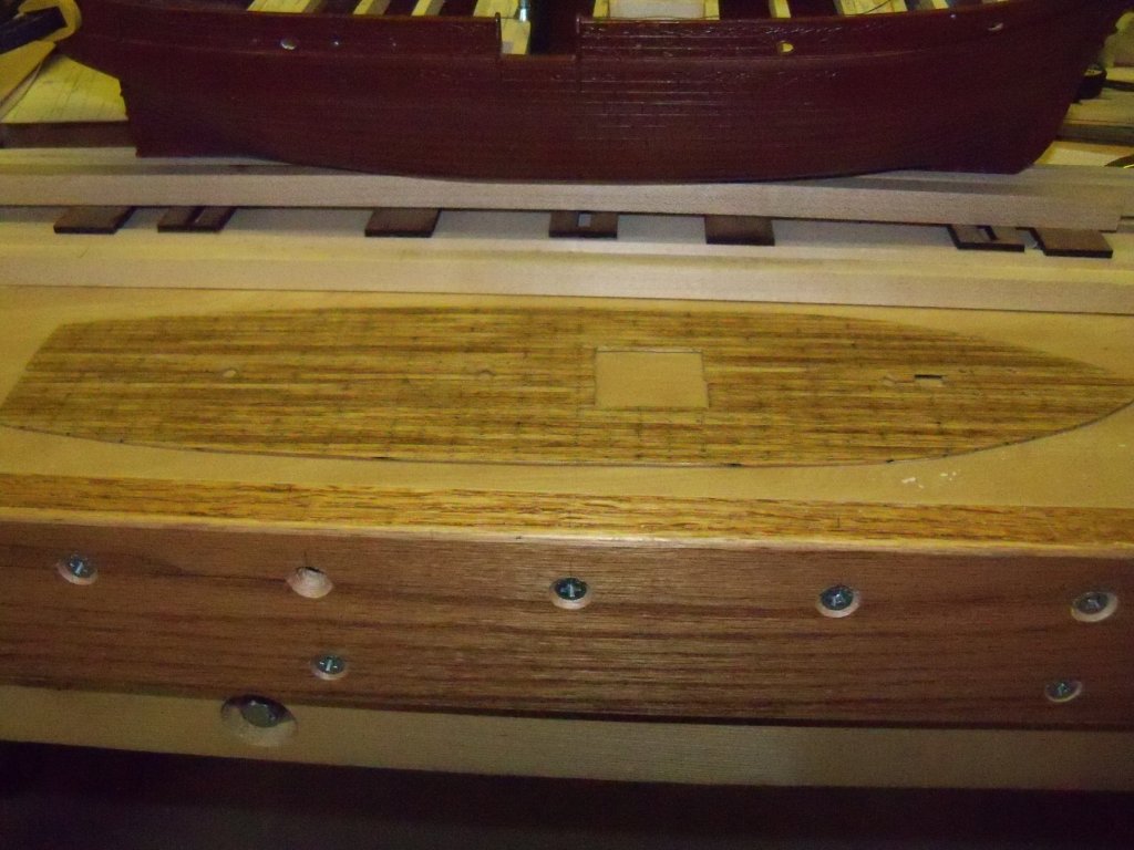
I scraped down the decks, put a light coat of Minwax light oak finish on it, let it dry briefly, and ran a rag over to remove the excess stain. After letting it dry, I put 2 coats of polyurethane over it while lightly sanding between coats with 400 wet/dry sandpaper. As you can see, the treenail and caulk impressions left showing provided a nice bit of detail even though it’s probably a bit over scale. Here is a photo of the deck with its finish applied. Almost forgot to duplicate the fore deck. Using rubber cement, the plastic deck was glued down to a section of wood decking, carefully lining up the deck seams with the plastic pattern. I shaped the deck section with my belt sander using the same method that I used to make the main deck. The center notch for the bowsprit was carefully cut out by hand with a thin fine toothed backsaw and finished off with a fine file and sandpaper while still glued to the plastic pattern. Very carefully, the pattern was peeled away (at this point it was very fragile) and the bottom side of the decks surface was filed to match the bevel of the bowsprit. Treenail impressions were made and the deck was finished as shown here to match the main deck. Now that the hatch and mast partner beams were done and clamped in place, I used plastic cement straight out of the tube, applied it to the keel seem, and set it aside to dry overnight. Taking the deck pattern in hand, the remaining beams were located, numbered and drawn in place perpendicular to the center line. Using my rubber cement again, the remaining beam blanks were glued in place on the deck pattern, numbered and set aside to dry. Once dry, the pattern was flipped over. Now the projections were marked on the beams which gave me the proper curve going into the hull sides. By drawing a line inside and parallel to this marked line (to allow for the ledger thickness), the length of the beams at the top edge of the ledger could be followed. However, with the varying slope of the deck sides to be accounted for, both ends of each beam had to be filed to match. (The cuts were basically a curved compound angle.) A very tedious business this! (This was especially true at the three beams at the bow.) Every beam was different and you had to go at it carefully or you could take off too much. After a lot of time trimming to fit, the beam ends were then located with the dividers and marked on the ledgers. Now some real fun began. As clamping the beams in place was not feasible, each beam had to be held in place with a locking tweezers while applying some thin CA. (At times I thought that I could really have used another pair of hands!) While waiting for the glue to take hold was in reality just a few seconds, it seemed to take forever trying to hold the beam steady. Most of the ships main deck frames have now been installed, but I am unsure at this point about having the main hatch left open or not. I am also unsure about leaving the transom as is or removing it and replacing it with wood as you can see here that the plastic seam is a poorly matched fit. That is why the final three deck beams haven't been installed yet, as I need to leave a little access space to get the lower deck slipped into place and replacing the transom.

- 107 replies
-
- 10
-

-
Show pictures of your work area
BETAQDAVE replied to a topic in Modeling tools and Workshop Equipment
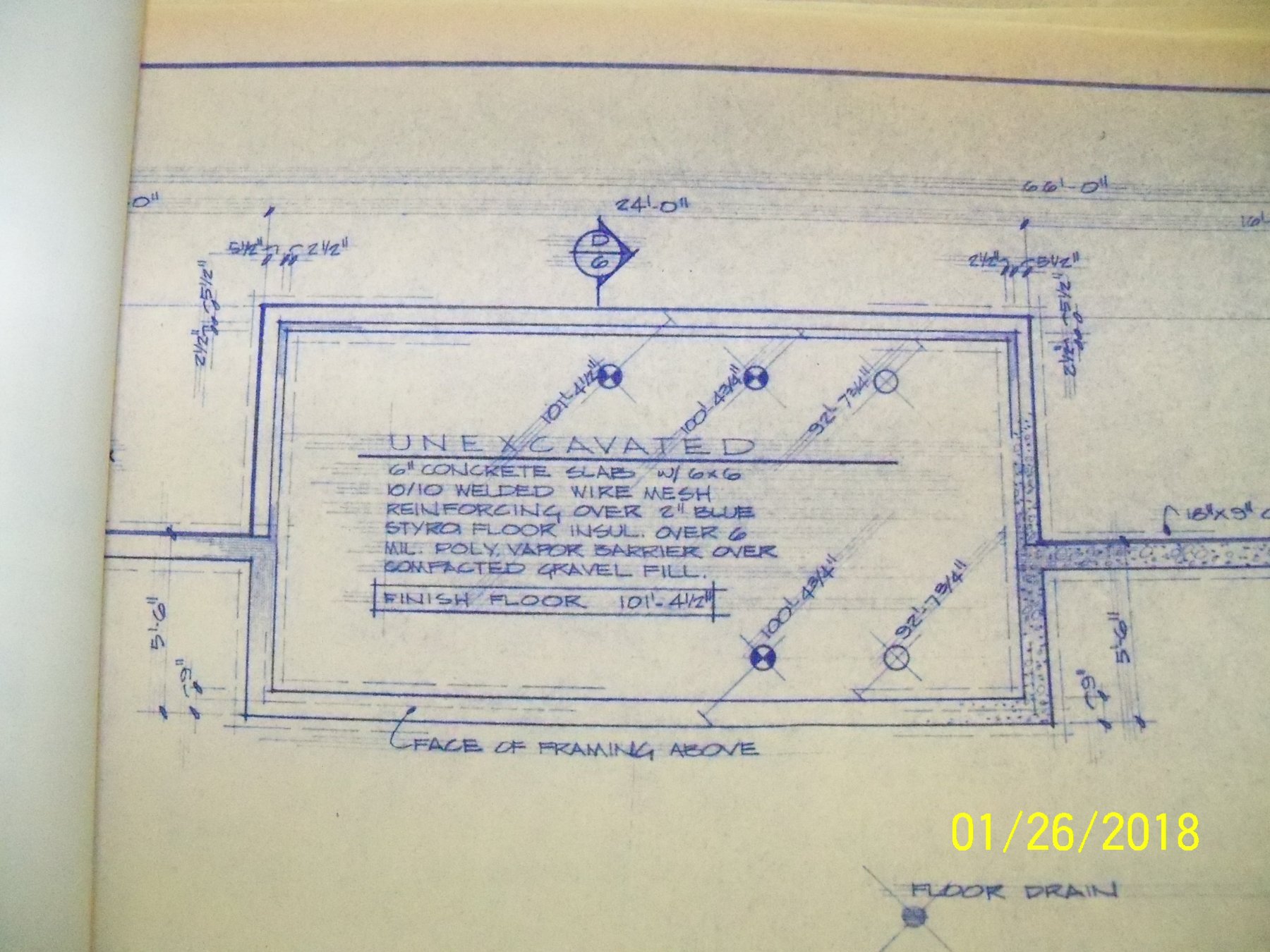
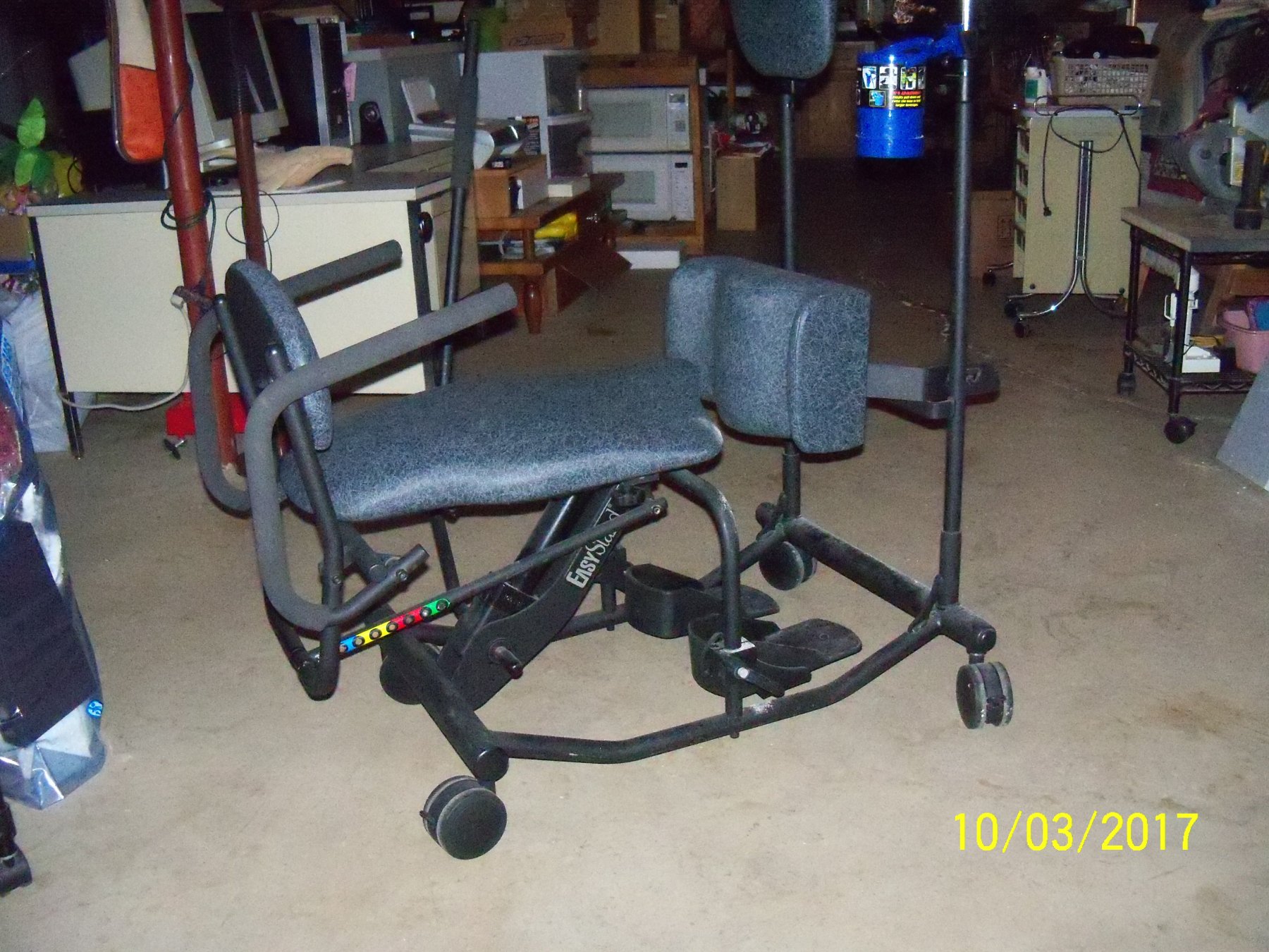
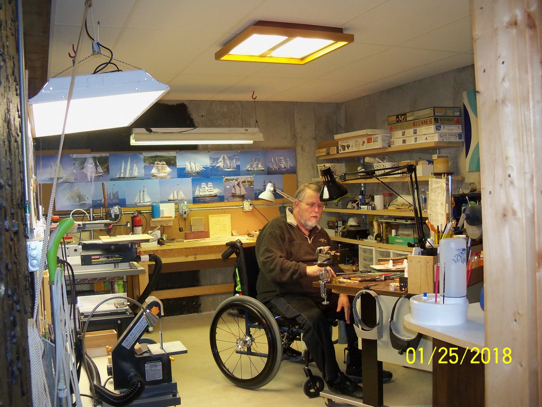
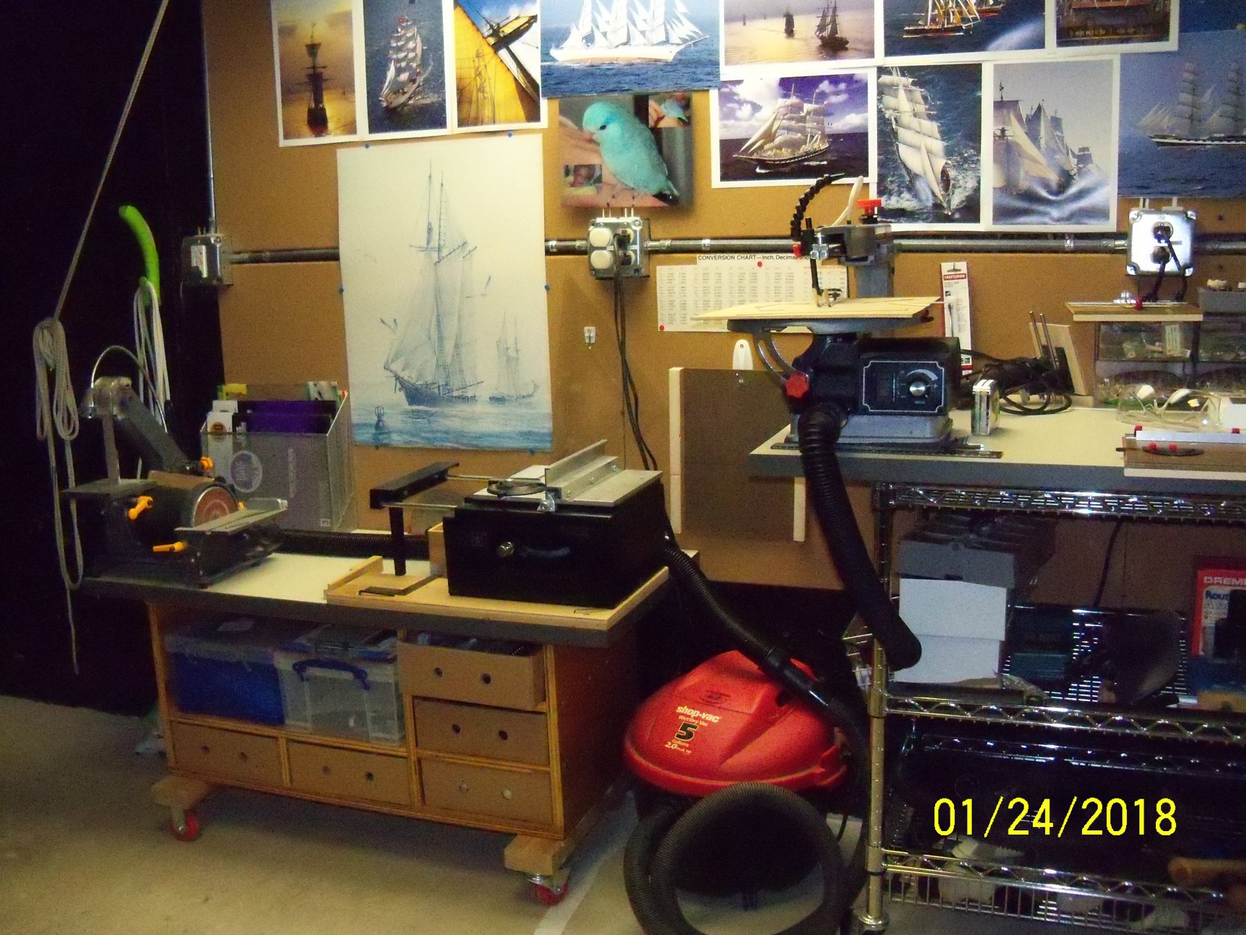
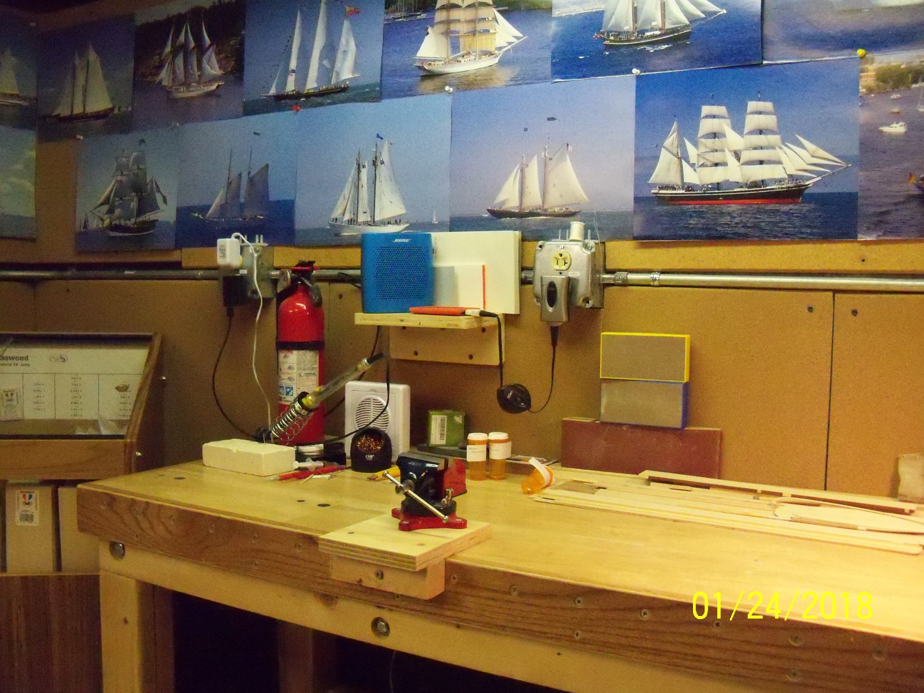
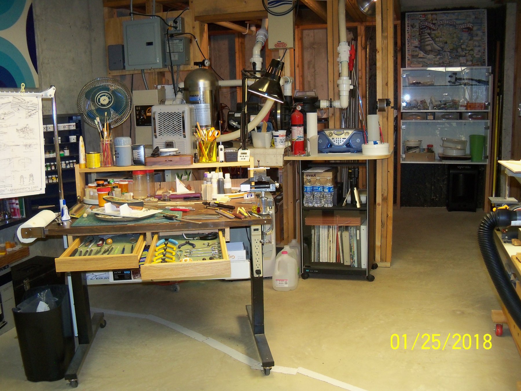
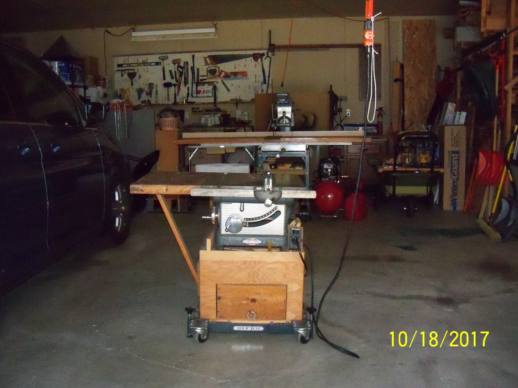
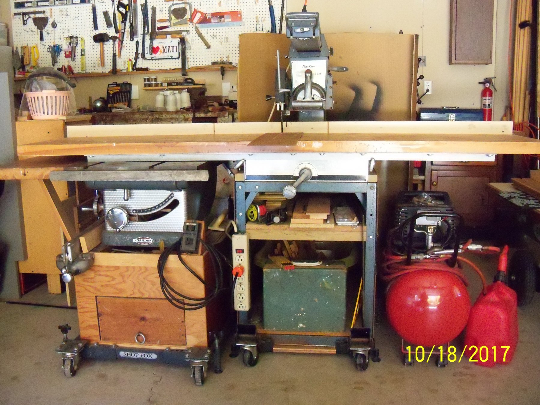
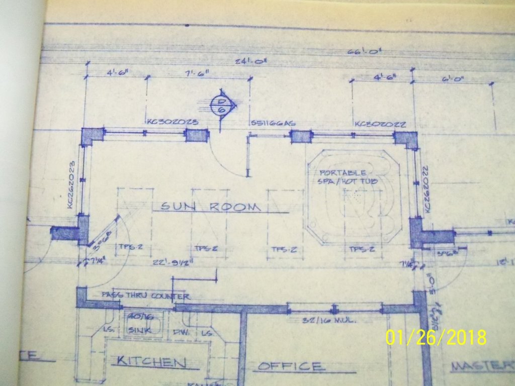
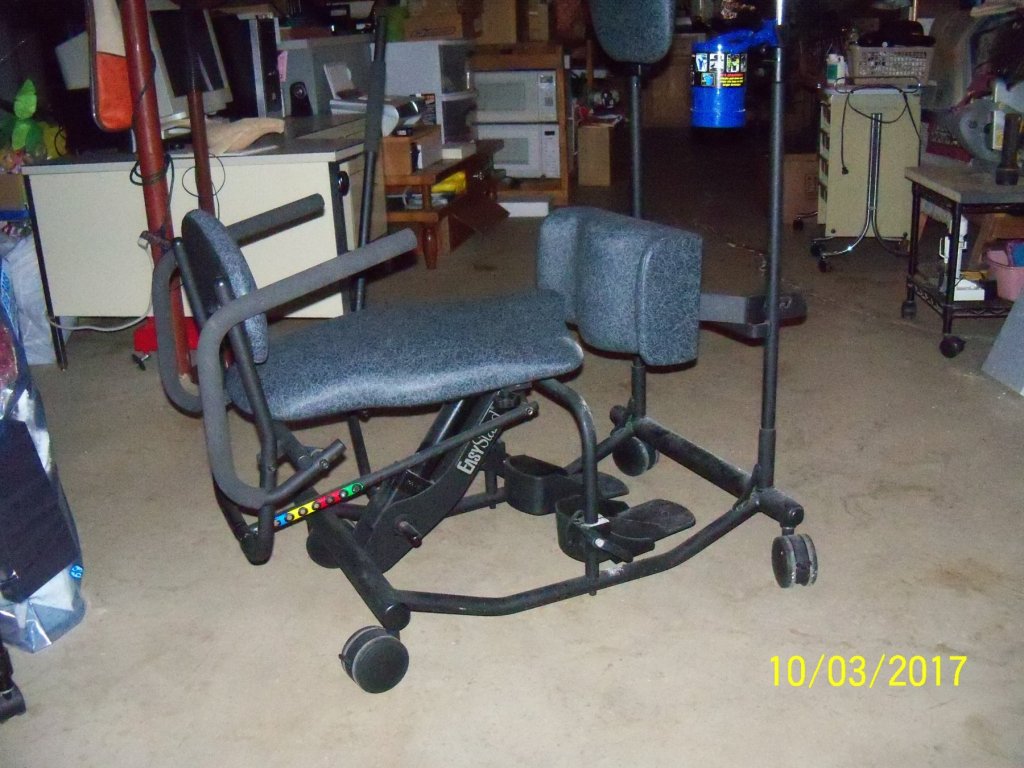
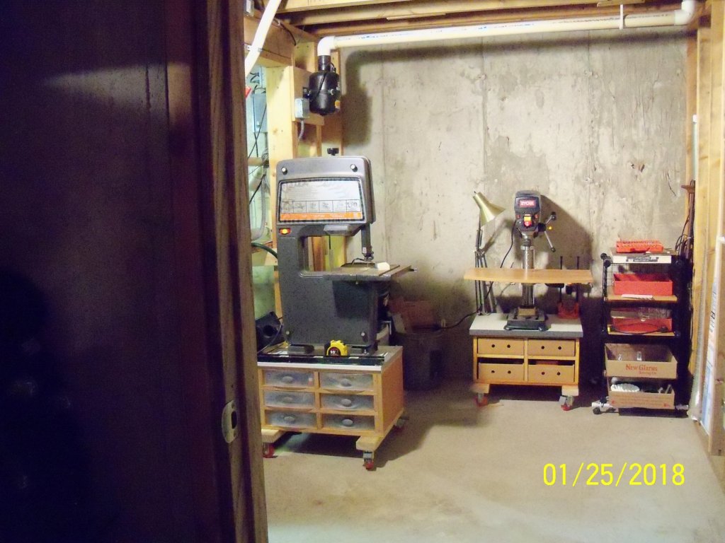
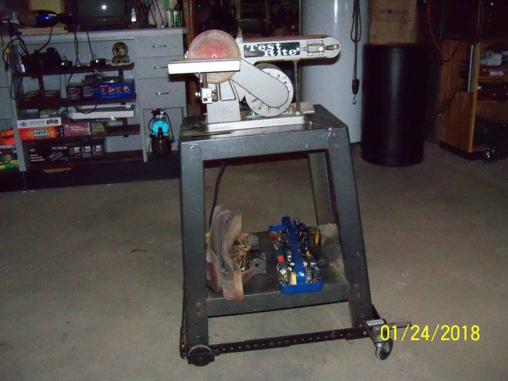
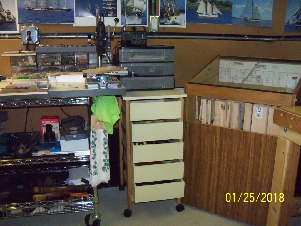
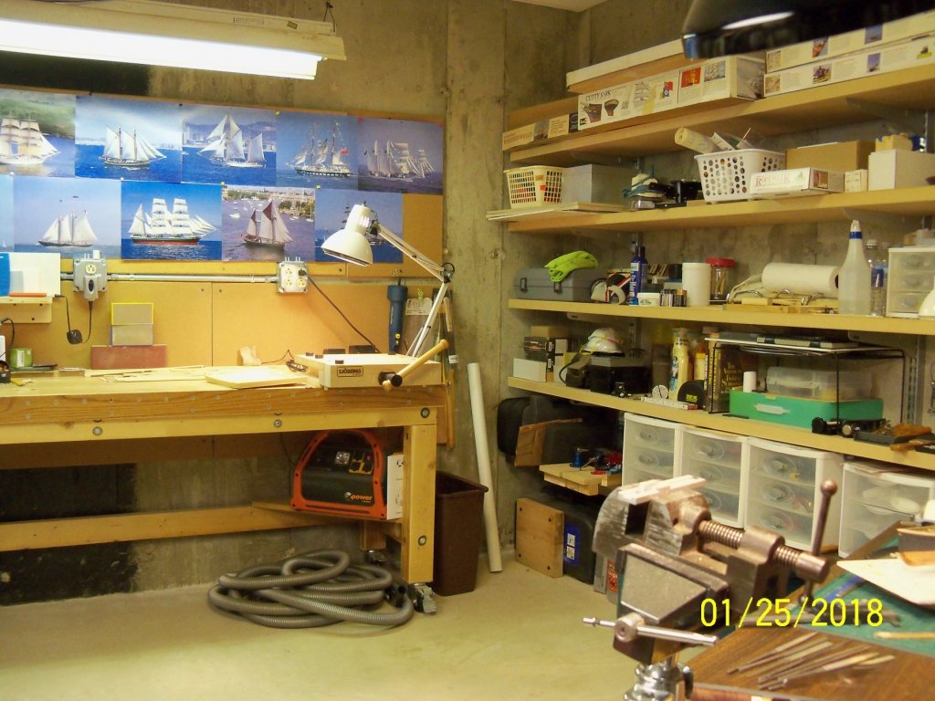
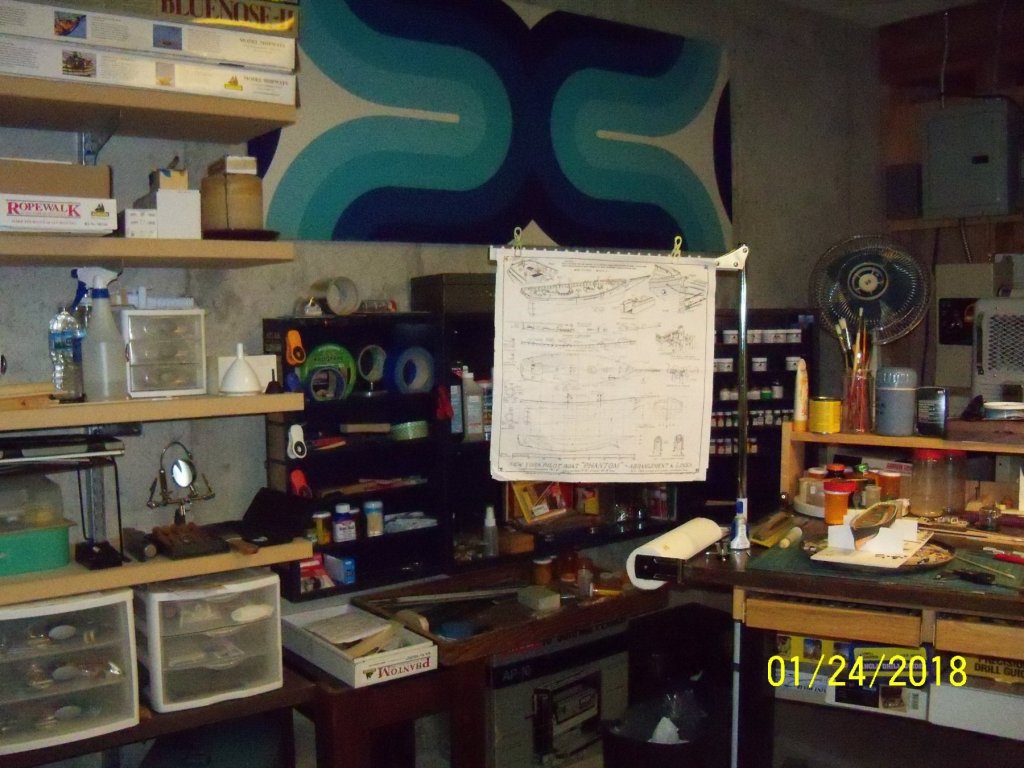
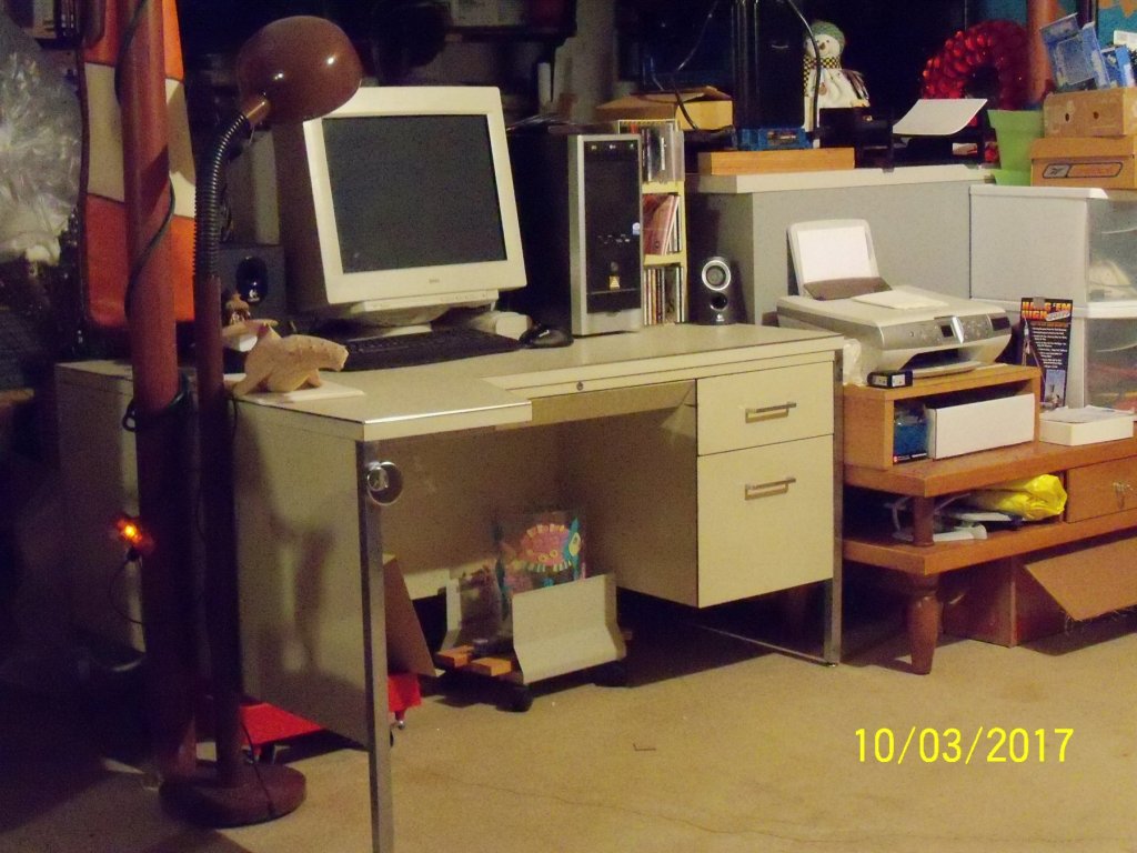
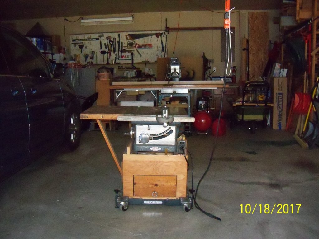
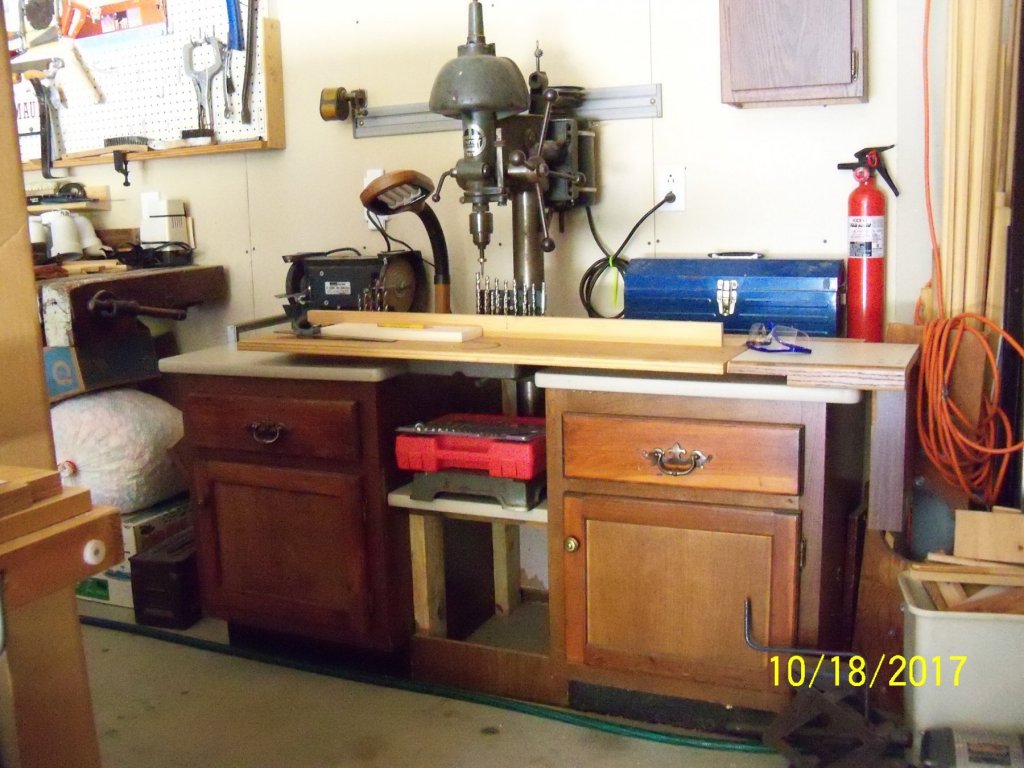
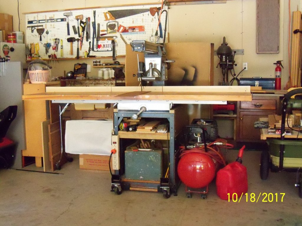
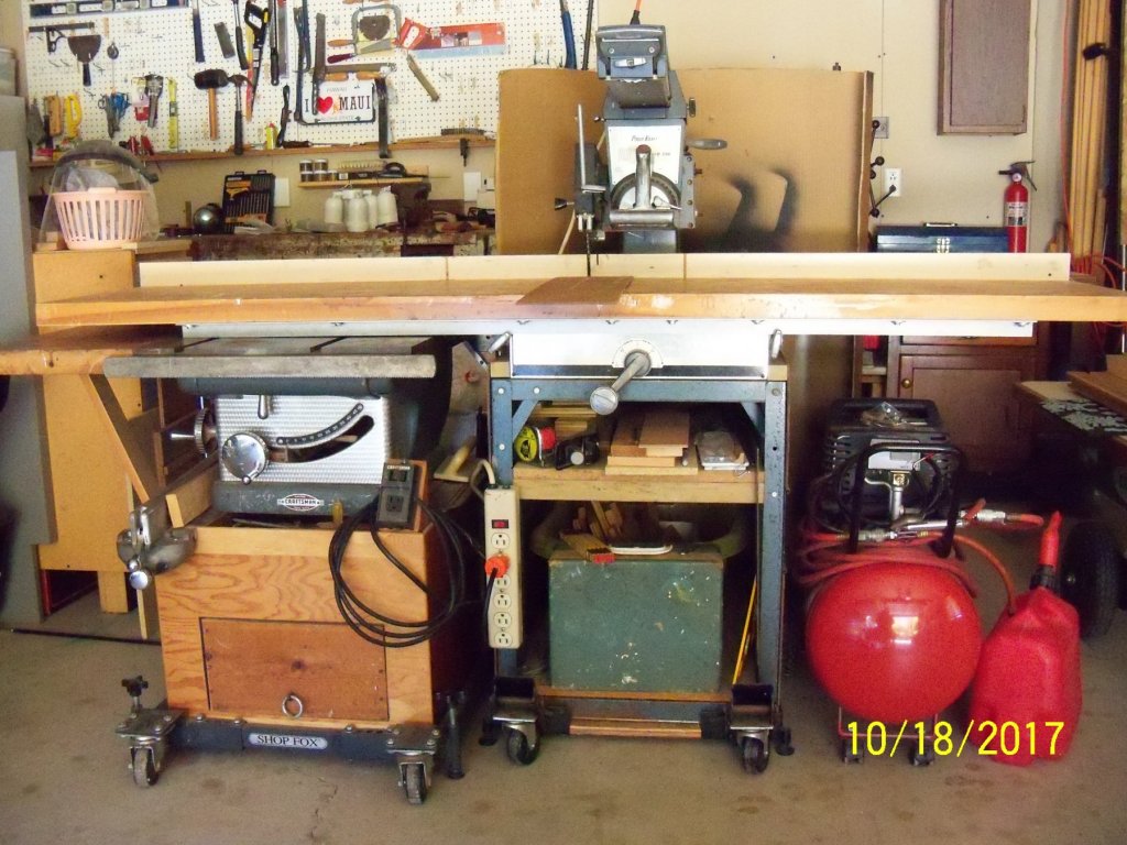
My shop is located below our sun room that has a sunken hot tub. (Here are two shots of the area from my blueprints.) Originally that area was designed as a slab on grade with frost footings and compacted fill. Due to grade changes, the frost walls became full height walls. After the foundation was done and waterproofed, I found that it would be a cheaper option to put a wood framed floor above and a basement floor slab below than to haul in and compact that much fill, plus it would just make that much more usable space in the basement. So I decided to have the builder cut an opening through the separating foundation wall for access to that area. Eventually, after having used the hot tub regularly for many years, it developed a lot of problems leaking from inaccessible (short of pulling out the tub) areas so we decided to just drain it. (As it turned out I wouldn’t be able to get in and out of it any more anyway.) So I thought that the area would be a perfect area to set up my model shop as it had its own power sub-panel, basement floor drain, and with the addition of a solid core wood door and a vent fan to the outside, it could be separated from the rest of the basement. (Just trying to keep saw dust and flammable vapors away from the furnace.) It was also a better alternative than continuing to use my unheated garage shop area, considering our WI winters. But then, right in the middle of all my remodeling, I found myself confined to a wheelchair, which kind of made finishing the rest of the room just a bit more challenging. If not for my stand-up frame shown here and a helpful neighbor it couldn’t have been done! I also ended up having to modify all of my stationary power tools so that I could still use them. Perhaps reading this posting may give other people with disabilities some ideas on how to make the best of it. I installed additional outlets and ceiling lights. I also had a white finish acoustic ceiling installed by a friend to help brighten up the room. Almost all of my equipment was made to be mobile on casters to make it easier to move around. (I no longer have the strength I used to have) Running my power tools in the room still proved to be a bit too loud, so I tacked up some cork bulletin board panels over the black tar waterproofed concrete walls with a few tap-con fasteners and fit them around the electrical conduit, which had the added benefit of lighting up the room some more. (Adding several years’ worth of nautical calendar photos to the cork panels didn’t hurt either.) Here is the entrance to the band saw and drill press area (approx. 7 ft. x 11ft.) of the shop below the sunken hot tub above. My Dads old Craftsman band saw needed a much lower base, so I removed the metal stand and made a custom roll-around cabinet with some ¾” birch plywood, ¼” hardboard, 2x4’s, 2 1/2” locking casters, an old piece of countertop, and some recycled plastic drawers. I designed it similar to my other bases but mounted the motor on a hinged shelf. (The motor projects into a gap in the stud wall) Beyond the band saw is a Ryobi drill press mounted to a similar base but I used some cardboard box bottoms from quite a few orders of premium pears for the drawers instead. Here is the reused old band saw stand on its roll-around base with a heavy generic disc/belt sander mounted on it. (I can use it in the garage for the real heavy sanding jobs where I can be wheel it outside if necessary.) This is the entrance to the main part of the shop, (approx. 11 ft. x 15 ft.) where I seem to be hard at work. (Or play?) Here is a small generic belt/disc sander and a MicroLux table saw mounted on another one of my custom wheeled benches. I have a small (but quiet) shop vac next to a converted roll around kitchen cart that I used a recycled heavy piece of solid laminate for the top. It has a Craftsman scroll saw bolted down on one end (It’s at a perfect viewing height for me in the chair.) and a couple of movable cutting/sanding jigs that mount on some threaded inserts. This is the rest of the kitchen cart with all of my Dremel tools including a drill press with a Proxxon XY table. Next to that is a roll around drawer cabinet re-purposed for misc. supplies and hand tools (Formerly a waxing station reclaimed from my wife’s closed hair salon minus A LOT of scraped off wax!) with a small reused plastic drawer cabinet and a weather radio on top. (Also from her shop) Next is a modified roll-around retail sales case for basswood storage. (I picked it up at hobby shop closing and trimmed 18” off the bottom for easier access from my wheelchair.) This is the soldering station end of a custom designed heavy duty roll around workbench I built to allow my wheelchair to roll under. By using the top row of wood screws on the face of the bench, that allows me to temporarily mount some interchangeable plywood base-plate mounted tools including a small metal vice (that is shown mounted here), an anvil, and several bending jigs. A shelf for my I-pod and Bosepowered speaker is mounted above. This shows the rest of the heavy duty bench with a portable Sjobergs wood vice (several threaded insert mountings allow various different placements) and a portable desk lamp. (With several pre-drilled mounting holes also.) Next to that, I have some general storage made from metal shelf supports set on the basement floor and bolted to the foundation wall with shelving made from some salvaged 1 3/8” hollow core bi-fold door slabs. (All of my basement shelving is made with these slabs. They are light weight but are still very sturdy and resist sagging quite well. The rest of my general storage including an old steel hinged auto parts wall cabinet salvaged from a closed gas station and several plastic drawer cabinets. (From my wife’s shop of course.) This is my primary modeling table. (It’s a very sturdy recycled roll-around computer station with a shelf and a desk lamp that I added to the top.) I added a homemade plan holder, a power strip, and two drawers made from some extra roll out trays from our pantry cabinet added below. Beyond the modeling table I have a roll-around steel tool stand with a fan for hot days and an electric heater for the cold ones. Also next to that on the floor I have a dehumidifier and my old stereo cabinet with a glass door for reference materials below. It has a brush cleaning station and radio/disc player mounted above on a sink cut-out from an old kitchen countertop. (All of that stuff on that dividing stud wall behind everything is all of the equipment for the hot tub above.) Just outside of the shop is a computer dedicated to modeling only. It’s not connected to the internet at all, so no crashes for my info. (It’s also safe from all of my modeling dust.) Besides the basement shop, I still had the full size equipment in the garage that now also needed customized bases. Everything was too high for someone in a wheelchair to adjust, operate safely or maintain. My Grandfather left my Dad his old Craftsman cast iron top table saw and Dad built a two wheeled semi-mobile dust catching base for it. When that saw was passed on to me I originally just remounted it on a fully adjustable four wheeled roll-around base, but now being in a wheelchair, the table top was right at my eye level. Not the safest situation to say the least! So now I unassembled the base and cut the height down about 18” while still retaining the dust drawer below. Now it’s not ideal, but definitely more usable and safer. Now I can still cut my own planks. Also handed down from my Grandfather is this very heavy duty Walker Turner ½” bench top drill press. For this tool I took two old reclaimed kitchen cabinets, cut 18” off the tops, remounted the drawers for drill accessories, cut the doors down to fit, added a couple sections of solid countertops, and placed them about 12” from each other. I mounted another section of that solid countertop between them to lower the drill enough to bring the drill controls within my reach. The biggest shortcoming of the drill press was that the table had no lift mechanism and as the table was very heavy it was too tough for me to lift it from my current position. Other than that, its large capacity still comes in quite handy at times! The last tool, and probably the most used, is my Dads old Power-Kraft radial arm saw that he mail ordered from Montgomery Wardsback in about 1960. (Except for the motor, it came totally unassembled in a couple of wood crates.) This included a heavy gauge steel base that I had previously put a wheeled base on, but once again this saw was too high for me. After a lot of work with just a hacksaw, I managed to shorten the legs, enclose the space below, add a shelf, and reassemble on the mobile base. The power switch was bad and stuck in the on position. The replacement switch was no longer available, so I mounted a power strip to plug it into and use that to turn it on and off. I had to carefully measure the height from the floor to the bottom of the radial saw table top to allow the table saw to nest under it and save some room in the garage. (For the cars, since that’s what a garage is really for, right?) As you may have guessed by now, I am one of those people who really believe in recycling. (We really have become a “throw-away society” haven’t we?) If I can modify or fix something to suit my use, why spend money to buy it new. (Especially since a lot of the “new and improved” versions of that equipment are probably of poorer quality anyway.) Being in a wheelchair now, finding new tools that would work for me now would probably be both hard to find, and a lot more expensive anyway. Personally, I have found out the hard way that it seems that if someone is to be handicapped they should first be rich! It seems that every piece of handicap aid equipment that you need starts out at about three grand. My current manual wheelchair that I’ve had for about ten years now, for example, ran about $3,400. Eventually I’ll be looking at some kind of power chair that comes in at two or three times that, not to mention some kind of conversion vehicle to accommodate it! But, all things considered, I still feel more fortunate than most of the other people like me with muscular dystrophy. I just remind myself of the old saying “things may look bad now but then things could always be worse”, so just enjoy what you do have! The posting above was originally shown in: So where do you do yours then (model making that is) There are many replies there which would probably also fit in with this posting.


- 43 replies
-
- 10
-
-
Cutting Planks
BETAQDAVE replied to sfotinos's topic in Building, Framing, Planking and plating a ships hull and deck
Try using rubber cement. I have that micro-mark sander and use the cement with it alot as it has good adhesion and yet is easily removed for changing grits. I find that it also works great for gluing paper patterns to wood, plastic or metal for shaping as any residue left over is easily rubbed off with your fingers. -
Is that just 40 years of dust, or was something living in it? That's one real slick clean-up job!
- 11 replies
-
- 1
-
-
- eagle
- model shipways
- (and 2 more)
-
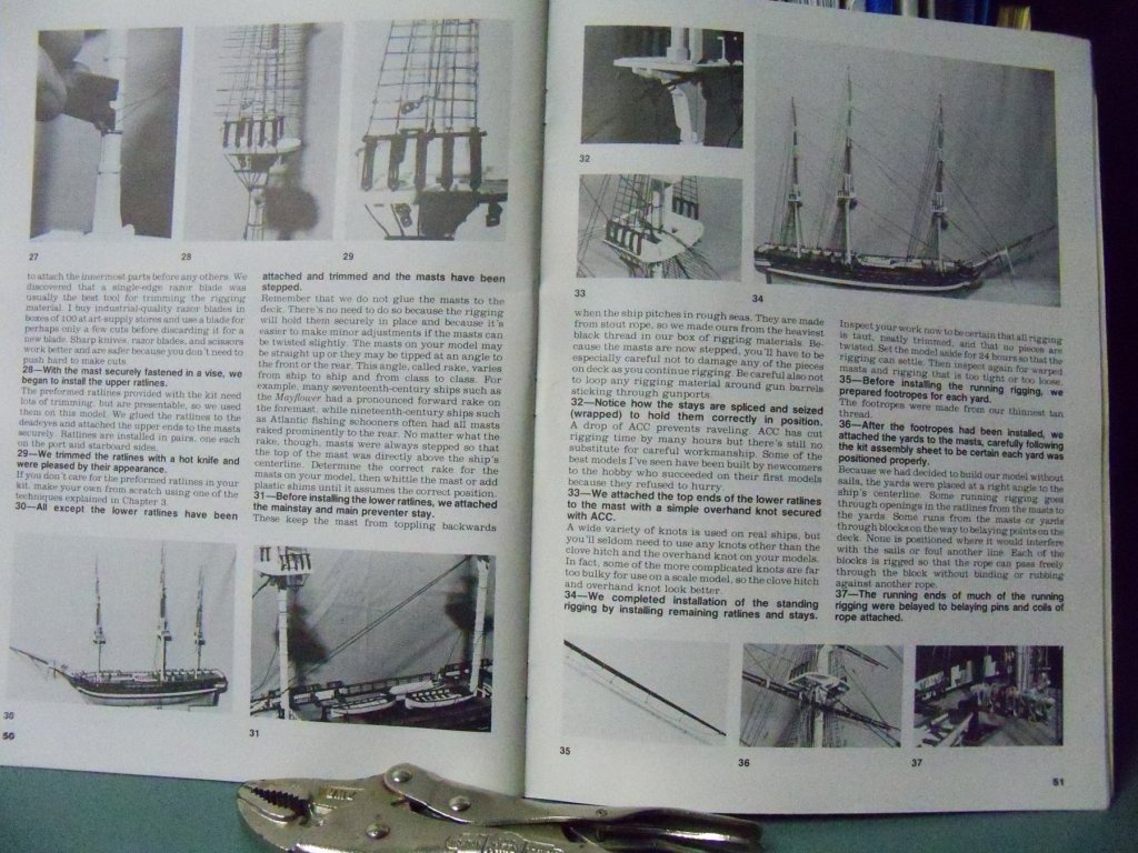
Yes, this would be a much easier method of eliminating the plastic deck seams and giving a much more realistic wooden deck complete with the difficult nibbing into the waterways. Believe me, I have done it twice for this model and it was not an easy job to substitute a wooden deck for the plastic one! An excellent reference booklet for making this model is How To Build Plastic Ship Models by Les Wilkins as seen below. He has one chapter that I referred to often, showing how a student of his converted the Constitution into the President from your kit. There are quite a few photos and diagrams showing a lot of details and techniques. As a mater of fact, several of his completed models are on display at the Manitowoc Maritime Museum in Manitowoc, Wisconsin that I have seen myself. I found the booklet a valuable guide.

-
Sounds like quite a large project at 42 inches long. I assume you have a very large shelf available to display it when you finish it. By the way, does the kit come with the 64 lifeboats that the ship was designed to carry, or just the 14 lifeboats, 2 cutters, and 4 collapsible rafts that were on board for the disaster?
-
A simplified version to be sure, but something that young children would really be proud of when they are are done. A very good subject mater to pique their interest.
-
MONTAÑES by Amalio
BETAQDAVE replied to Amalio's topic in - Build logs for subjects built 1751 - 1800
I just came across your posting #378. That's a very precise technique Amalio, for doing essentially perfectly fitting joints! As they say: "A picture is worth a thousand words." Your pictorial method of showing your method is just a perfect example of that saying. "It should be in a how-to book for modelers. -
I also am having to deal with MD, so I know something of its effects. (my version is Beckers) I found it a little easier to deal with once I discovered the limitations that I would have to live with, and how I could try to circumvent some of them. I know that there are also several other members here that also deal with various disabilities. Once I became confined to a wheelchair, I found that with some modifications to my tools and workshop, I could still do some ship modeling. See my posting in Shore Leave under the Where do you do your modeling for some of the things I have had to change. I do feel somewhat fortunate that I live in the US, as many things that used to be impossible to do with a disability, are now possible due to the Americans With Disabilities Act. I don't know how things are over where you are, but hopefully there are some allowances made for you. Welcome to MSW
-
That's a very nice job of illustrating your jig and its function. Overall, I found this to be a very instructive posting that shows your method of handling a rather busy piece of rigging without getting tangled up in all of those closely spaced lines and knots. Personally I have always believed that necessity can indeed be the mother of invention or innovation. Thinking up sometimes unique solutions to these problems before hand, almost always saves time and frustration in the end. (And besides, I think that is a good share of the fun involved in modeling.) Keep it up Jesse
- 1,306 replies
-
- 8
-
-
- syren
- model shipways
- (and 1 more)
-
Recommendation
BETAQDAVE replied to Jaeon's topic in Building, Framing, Planking and plating a ships hull and deck
I would check the fit of the rest of the keel before doing any sanding as it may affect the fit of the whole keel. By the way I hear that grsjax is now looking down the barrel of a major hurricane tonight. I hope his hatches are all battened down, well stocked for the long haul, and he isn't washed out to sea! We've made several trips to Oahu, Hawaii, and Maui with friends over the years and are very aware of the fact that there are numerous steep gullies and valleys to funnel all that rain down to the sea in a hurry. Wouldn't want to get in the way! Also with a very limited number of roads around the islands coasts, if they get washed out like things did here the other day, traffic and power may come to a halt for quite a while. Lahina and that whole area around it are within easy reach of any storm surge. Good luck to you and yours grsjax! -
Jesse Sounds like you are probably overjoyed about now that you are only building a brig and not a ship with three or more masts. With your limitations from your affliction do you stand to do the upper rigging or stay in your chair? In either case do you brace your elbows on some kind of support to steady your hands for doing fine work in those tight spots? If not, I would suggest checking the current posting titled working comfortably on upper rigging in the shop notes section. I know that some of the solutions are a bit pricey, but using some of your ingenuity, I would think you could come up with a solution that would work best for you. By the way, despite your difficulties, your ship is still coming along nicely! You should be proud of what you are building. I would be. Dave
- 1,306 replies
-
- 9
-
-
- syren
- model shipways
- (and 1 more)
-
I totally agree with that! It must be a real gold mine for identity thieves!
-
Personally, between these two, I would go with the Revell 1/96 scale Cutty Sark. For two reasons. The first and probably most important is its larger scale. Even at this scale there will be a lot of very small pieces to contend with, especially for the rigging. You will find yourself trying to reach into some very cramped areas with the rigging and the larger scale will allow you more room. The second reason would be that you will have much more of the type of detailed instructions that you are probably already familiar with. You will learn familiarity with many new terms not found in your previous kits, especially in the rigging. Once you understand the nuances of a tall ship you will be much more prepared to brave a wood version of them. With the plastic version of these ships, you are basically just making an assembly of pre-made parts. But with the wooden kits you will have to make most of these parts from raw materials before assembly and most wooden kits with their scanty instructions, will have you on your own trying to make components that you are not even familiar with yet. So, (my two cents worth) the plastic kit will make you better prepared to tackle a wooden kit, as at least you will have a working knowledge of the components that you will have to fabricate yourself and what all is entailed in making a tall ship. One other consideration would be to at least go with a much less complex and larger scale wooden ship kit as shown in Peter Ys' post above. Dave
-
Dan Just reviewed your build log now and discovered that you had a bout with the BIG C as John Wayne referred to it. My wife is also a cancer survivor and has been doing well for the past 15 years or so. Hope you also have a lengthy bout of good health to follow now. I was just wondering about the fact that major portions of the coach's cab appear to be some kind of plywood product. Was that just what they supplied with the kits model material, or was it in fact what the actual coach was made with? It seems that it would have been something very hard to form in such complex cured shapes, not to mention the fact that I didn't think that plywood was all that common back then. As far as your job of building the kit goes, I was impressed with how you were able to deal with the shortcomings of the kit and your improvements to it. To me, that is one of the aspects of model building that I like the most. Excellent job! Dave
-
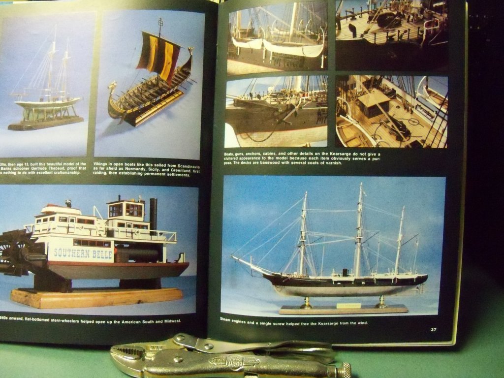
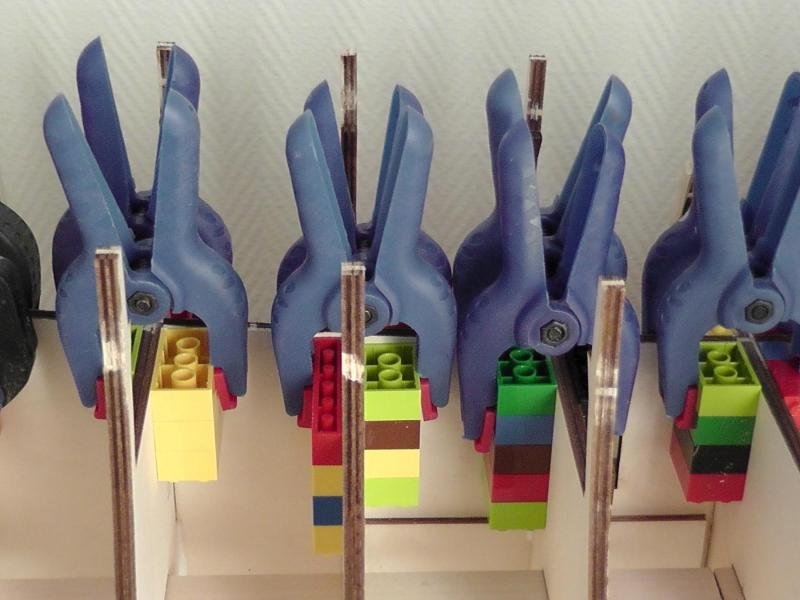
I am of the opinion that regardless of the scale involved, without an indication of caulking and the varied grain pattern of individual planks, the decks appear to be made from a large sheets of plywood. Hardly the impression we are trying to convey to the observer and nowhere near historically accurate. There appears to be a strong indication here and in very many other MSW builds, that LEGOS seem to be an internationally recognized product for clamping frames square! Looks like you were making a fast start on your model. Have you made any progress since these postings as I noticed the latest being from Feb. 2017? Hopefully there's no health or other kinds of setbacks as you were previously very prolific in your postings.
-
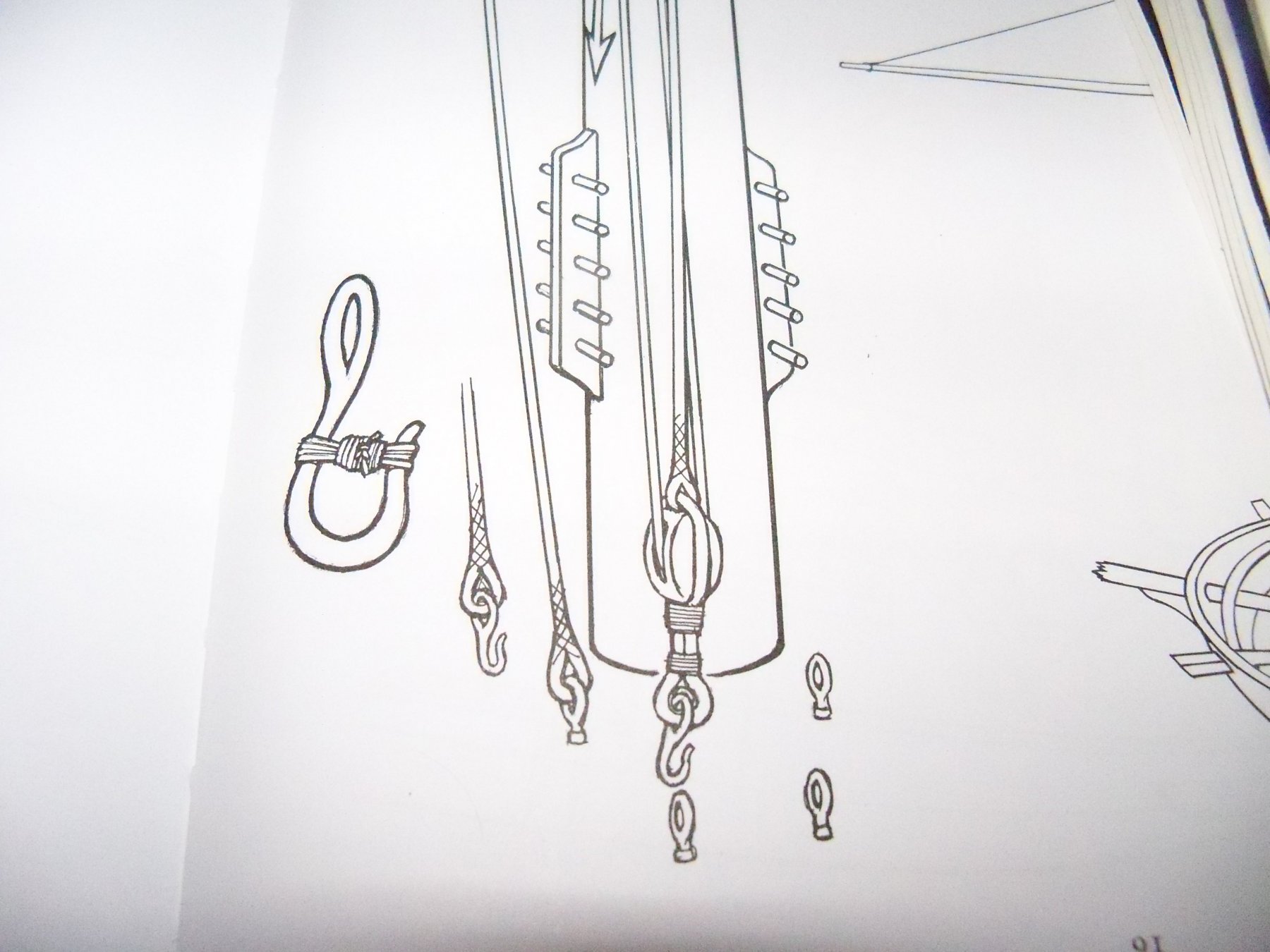
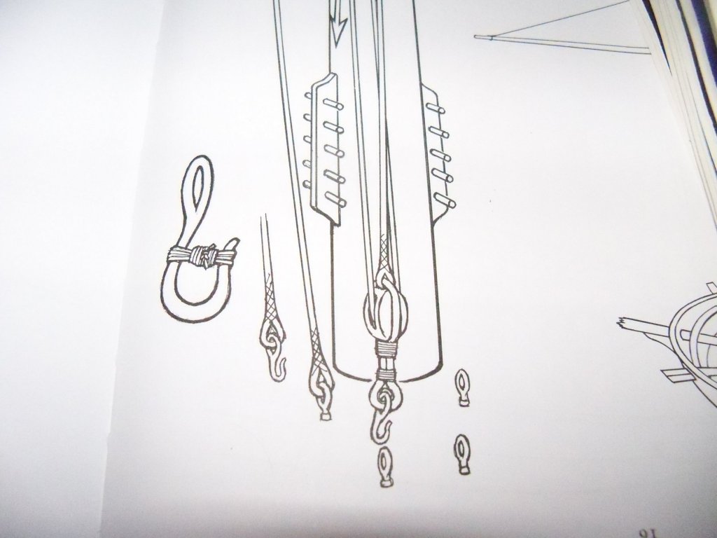
And don't forget that most hooks were moused to prevent them from coming loose when the lines were slacked off. See this illustration below taken from Rigging Fore-And-Aft Craft by Lennarth Petersson.
-
15' Dinghy by Bedford - FINISHED - 1:1 scale
BETAQDAVE replied to Bedford's topic in Non-ship/categorised builds
Like getting a new car and just obsessing over when it will get its first scratch or dent. Once you get it, you don't worry nearly as much. -
I usually tie small blocks to eye bolts while they are still off the ship, then install the bolt to the ship. Trying to tie knots thru the confused mass of rigging and fittings that are already in place is much harder than just installing the bolt to its place on the ship!
-
Well I guess that you better slow down then. At the rate you're going you should be done with all four of your ships by next summer! It looks like you have all the tools and the shop to "get er done" as they say at Home Depot.
- 34 replies
-
- 4
-
-
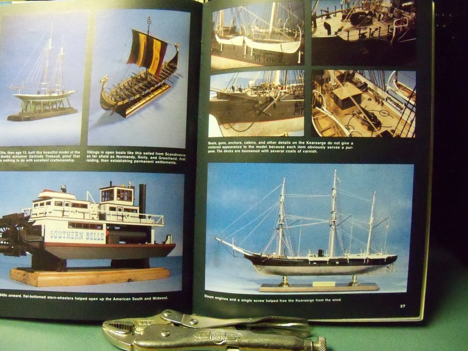
- kearsarge
- first build
- (and 1 more)
-
ancre La Salamandre by tadheus - 1:24
BETAQDAVE replied to tadheus's topic in - Build logs for subjects built 1751 - 1800
Just saw your latest post and went back to the beginning of your build to check it out. Not sure what the problem here is, but this is what shows up on my monitor for the majority of your postings. There are a few postings that show up normal, but not too many. That's a shame, as the postings that do show normally are very interesting indeed.