HOLIDAY DONATION DRIVE - SUPPORT MSW - DO YOUR PART TO KEEP THIS GREAT FORUM GOING! (Only 13 donations so far - C'mon guys!)
×


BETAQDAVE
-
Posts
5,386 -
Joined
-
Last visited
Content Type
Profiles
Forums
Gallery
Events
Everything posted by BETAQDAVE
-
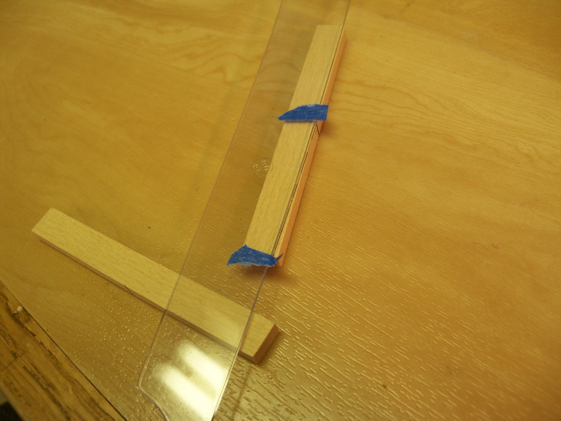
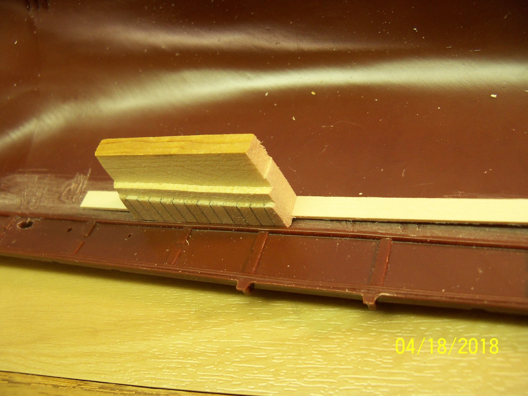
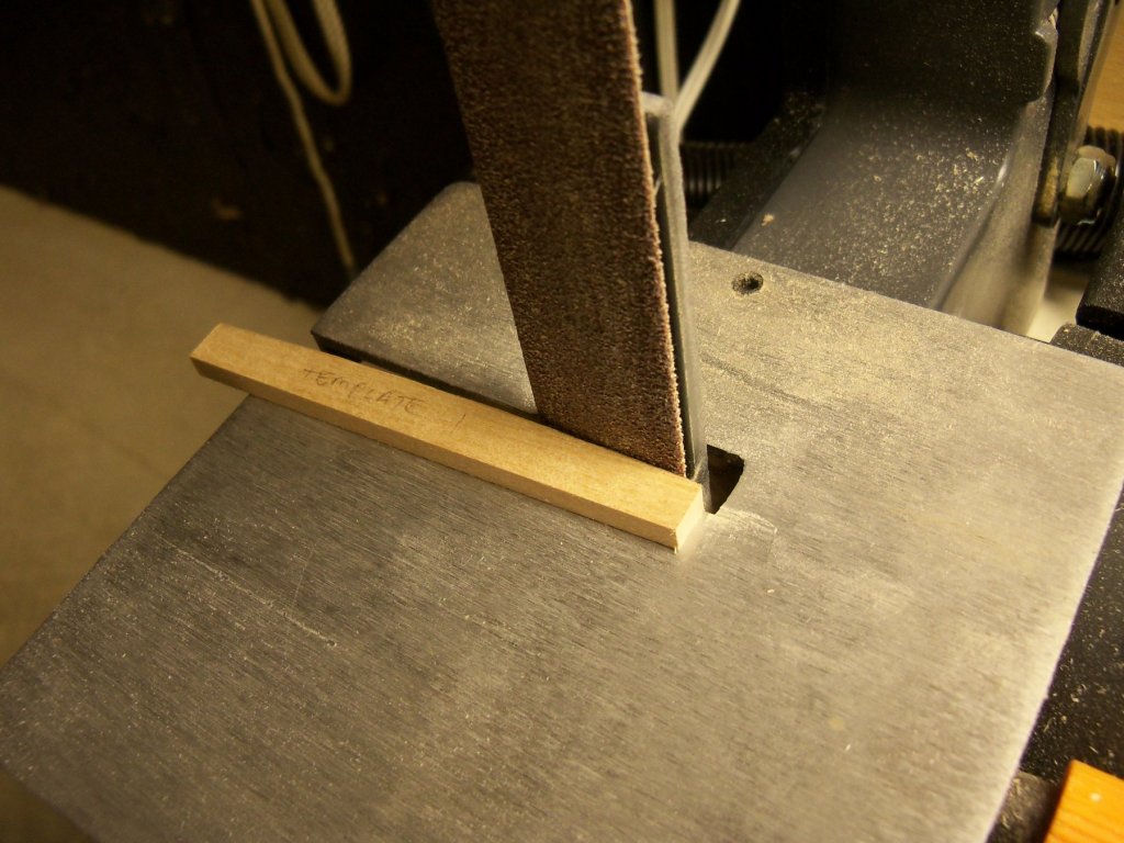
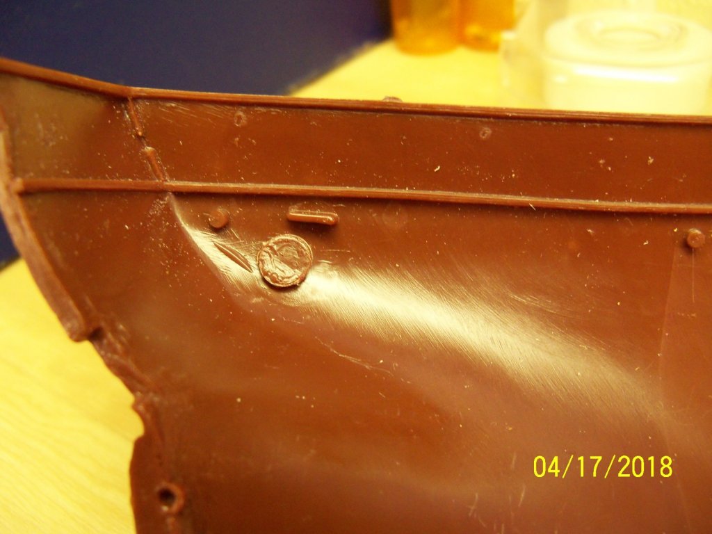
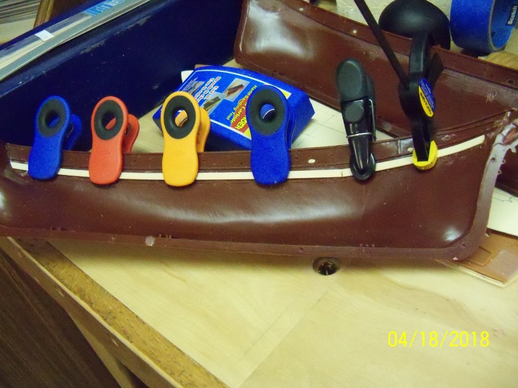
 Hi Doris What is your source for these foil strips? Are these part of your card ship kit or can they be ordered separately? The reason I ask is, on my current build log for my hybrid (as Jesse calls it) whaling bark Wanderer, the inside of the bulwarks as you can see here are just smooth plastic. I was thinking of lining them with a wood veneer to give it the impression of wood but am unable to get anything nearly thin enough to not bring the facing beyond the inside edge of the main rail. These strips that you are using could maybe do the job. Thanks
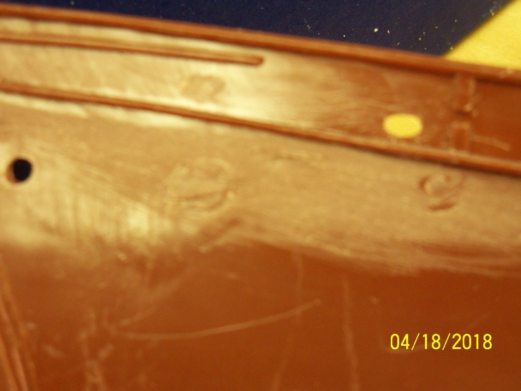
- 1,035 replies
-
- 5
-

-
- royal katherine
- ship of the line
- (and 1 more)
-
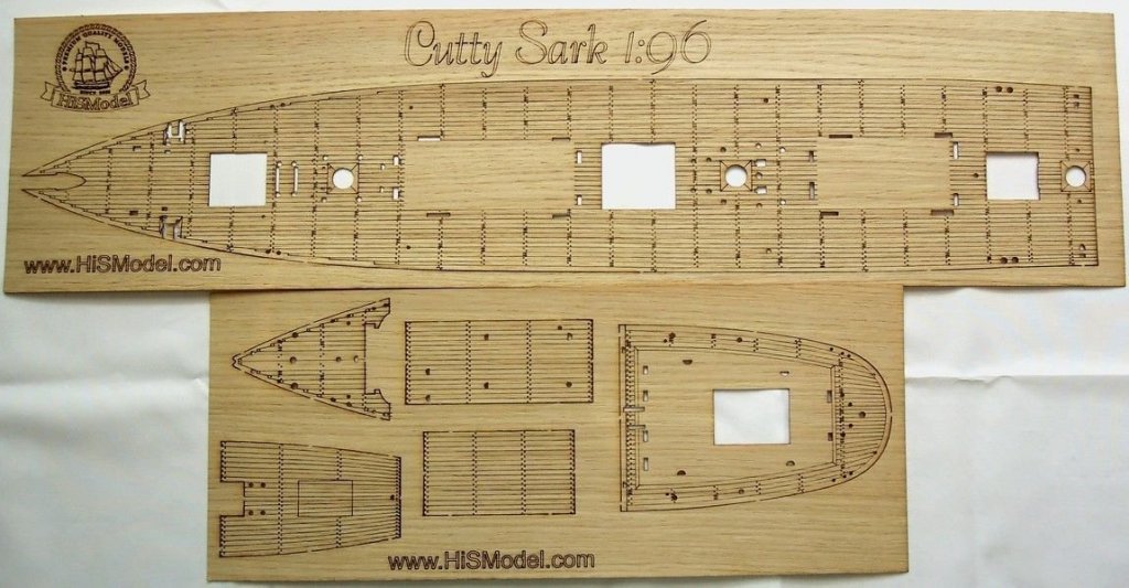
If you intend to put actual wood decking down or just draw it out, there is an add on wood veneer kit made for the Revell plastic model that I have shown below. This is made for a 1:96 scale ship but, if nothing else, you can you can use it as a guide for your planking layout.
-
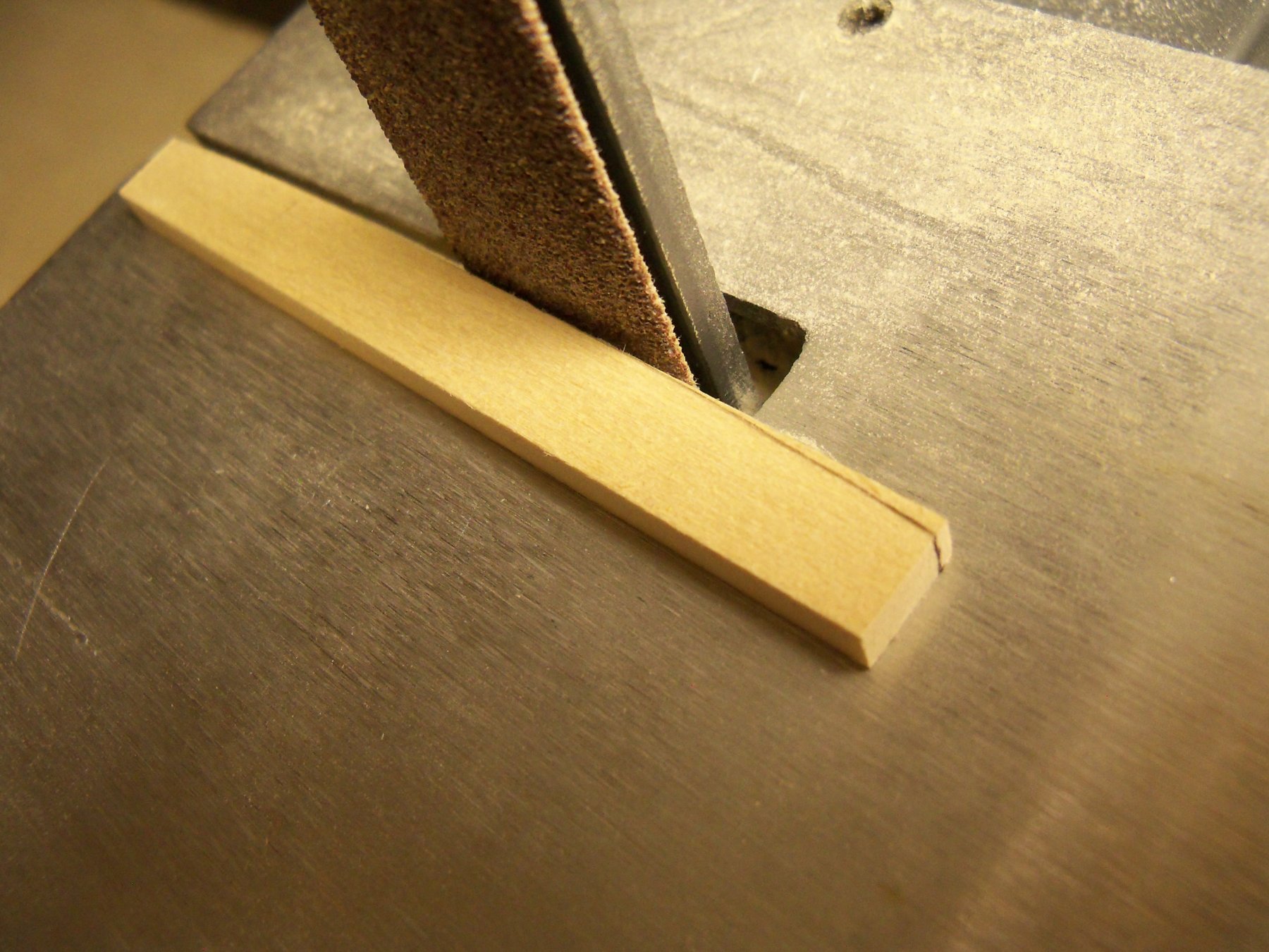
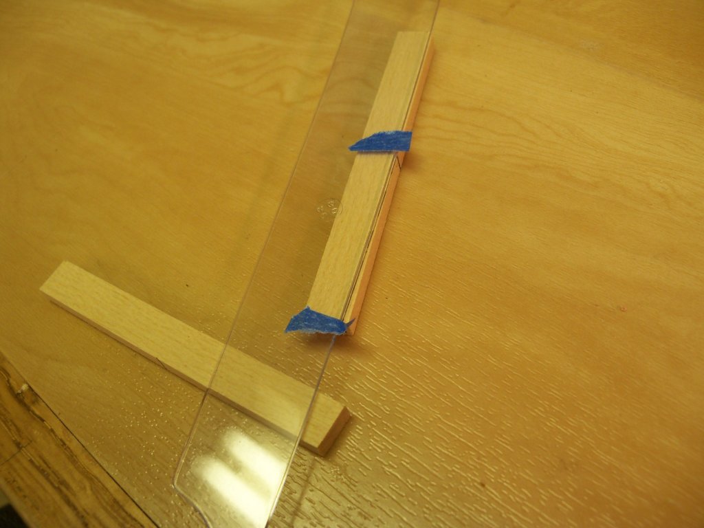
Another method would be to plane or sand the wood into much thinner planks which will bend much more readily. Then soak or steam the planks to make them more pliable and bend enough layers of these thin planks to total the required final thickness around a form matching the shape required and clamp to dry. When dry, laminate the layers with a thin layer of glue between and clamp the layers back on to the form and let dry. This may be a bit involved but with this method you can bend planks into very tight bends and there will be very little if any spring-back. Once trimmed and sanded they should be very easy to apply.
- 6 replies
-
- 2
-
-
- sark constructo
- on cutty
- (and 2 more)
-
bending planks
BETAQDAVE replied to bluenose2's topic in Building, Framing, Planking and plating a ships hull and deck
Another method would be to plane or sand the wood into much thinner planks which will bend much more readily. Then soak or steam the planks to make them more pliable and bend enough layers of these thin planks to total the required final thickness around a form matching the shape required and clamp to dry. When dry, laminate the layers with a thin layer of glue between and clamp the layers back on to the form and let dry. With this method you can bend planks into very tight bends and there will be very little if any spring-back. Once trimmed and sanded they should be very easy to apply. -
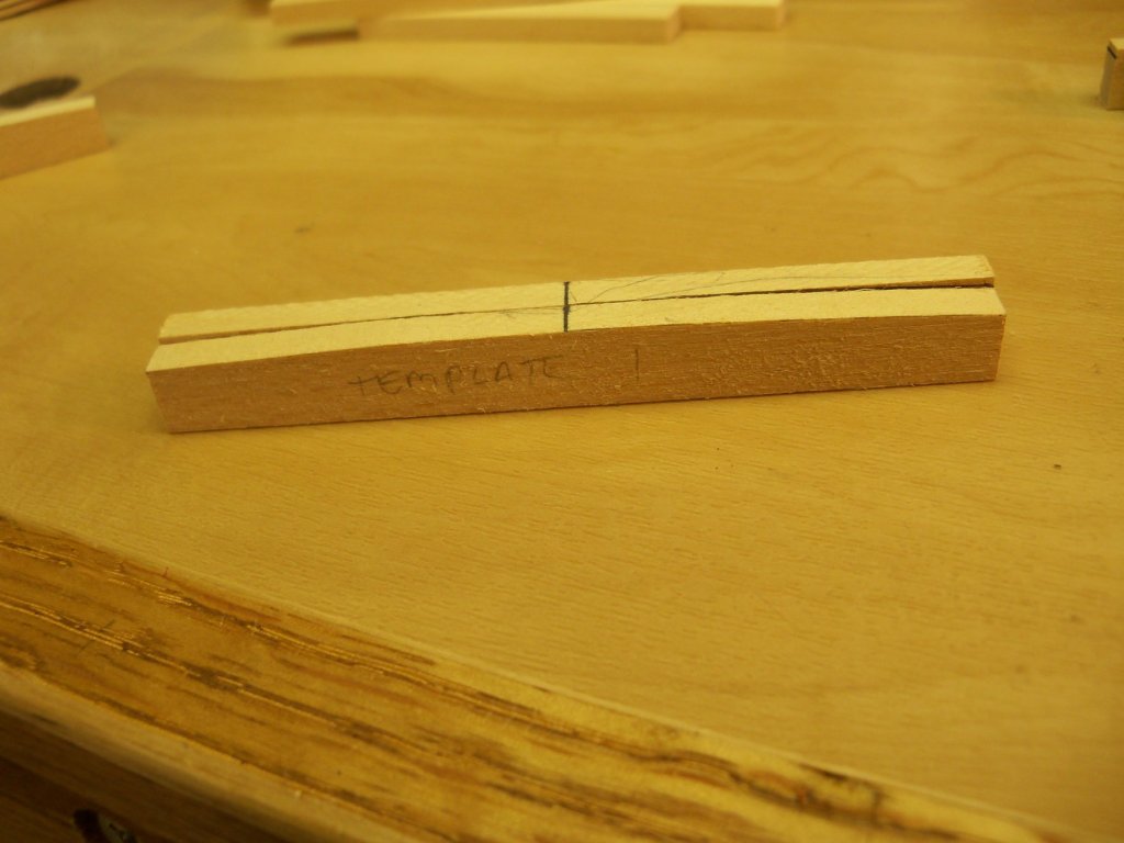
To shape the deck beams with the camber for the ships deck, I first found an appropriate ships curve. I traced around the curve with a .5 mechanical pencil with a soft lead installed from the center mark on the top of the beam to the marks that I had previously put on both ends of the beams. Taking this beam to my belt sander, (being careful not to sand off the marked center-line) I sanded down to the curve. (just taking off the line) Now, taking my micrometer to each end I measured them again and sanded the wider of the two of them till both ends matched. This beam was now marked template #1 and was used to make two other templates marked #2 and #3. Using #1 to make 5 more beams, I switched to #2 to make 8 more beams and finally to #3 to make the rest. Using the templates tends to wear them down if used too often as it was just made of basswood. With the beams shaped with the camber, I now took the two plastic hull halves to a sink filled with warm soapy water and scrubbed them down with an old toothbrush. This needed to be done to remove the mold release agent from the plastic to allow paint to adhere properly.

-
Great! I still think that your tall ship illustrations are some of your best stuff.
-
Thanks a lot for all the comments guys. This is one of the great things about this forum, many different views on just about any facet of ships, be it models or full size ships! I figured that someone here would be able to come up some answers, or at least where to look for them.
-
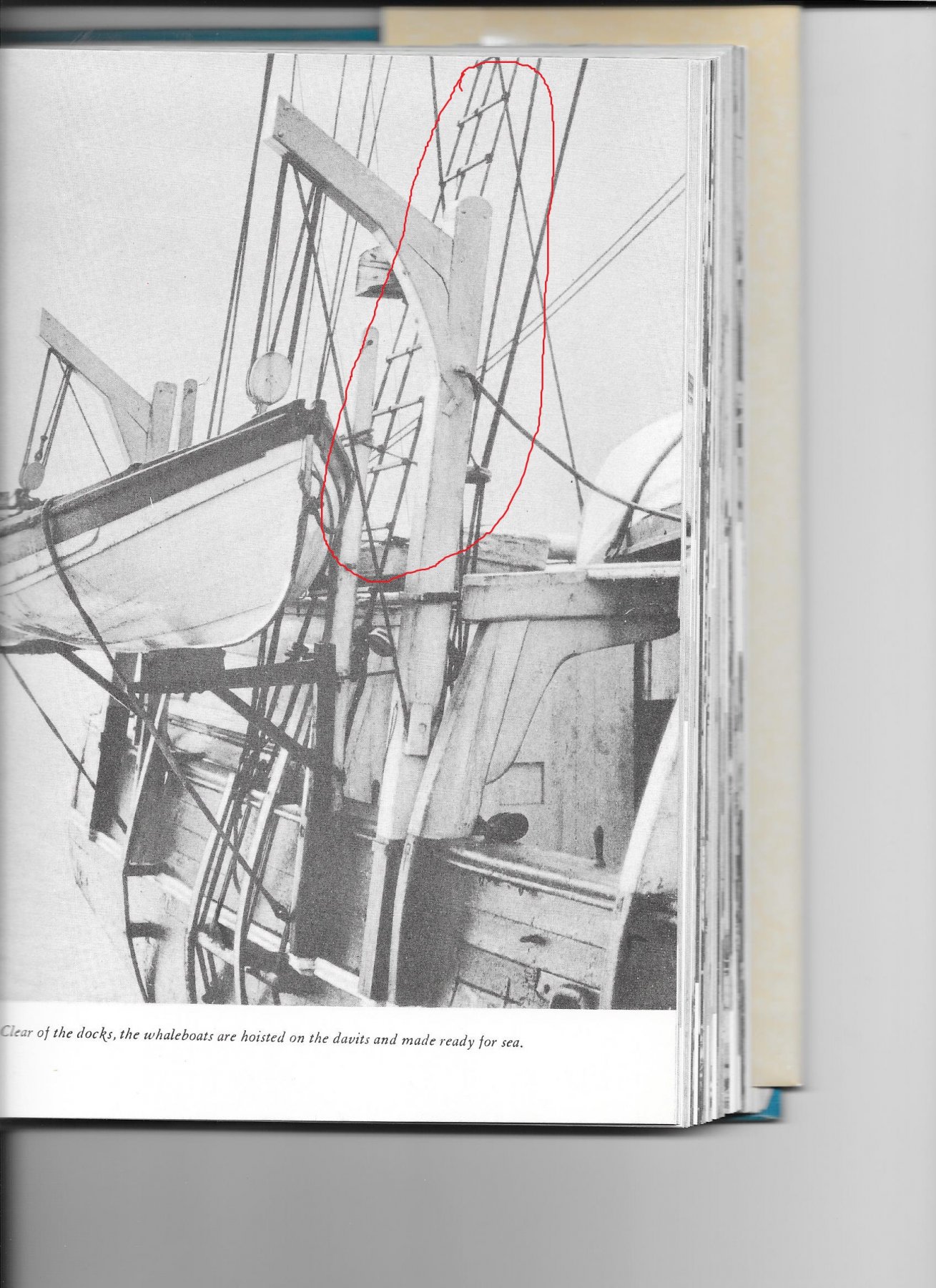
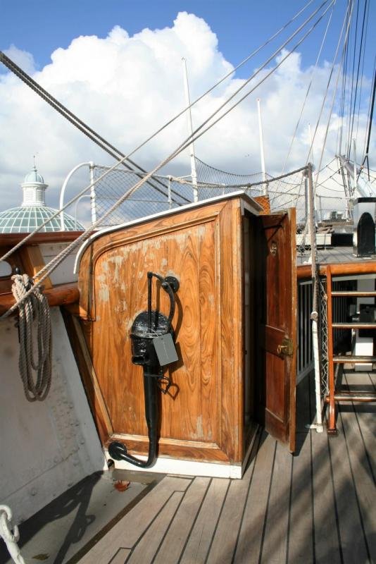
While researching the whaling bark Wanderer, I found that the ratlines were actually bars made from wood or metal. (not sure which but several other whalers were also outfitted with this feature) You can see them in the circled area of the photo below that they were attached to the face of the shrouds, but I was also unable to determine exactly how they were lashed in place. This is another detail that most contemporary models or plans of this ship do not show. (including the Aurora kit and the A.J. Fisher blueprints) If they were just tied in place, what would keep the ratline bars and the shrouds from shifting sideways? Did they have some kind of notch or pin in the ratline bar to give them better purchase to keep them secured, or would the lashing alone be enough? Does any one else have any suggestions? By the way this photo was taken from Whale Ships and Whaling by Albert Cook Church, and it is a real good source of info and photos on this ship and several other famous whalers, (including the Charles W. Morgan) if anyone else is interested in modeling this type of ship.

-
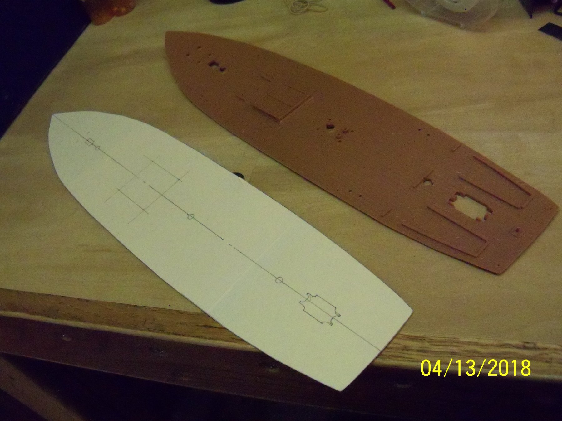
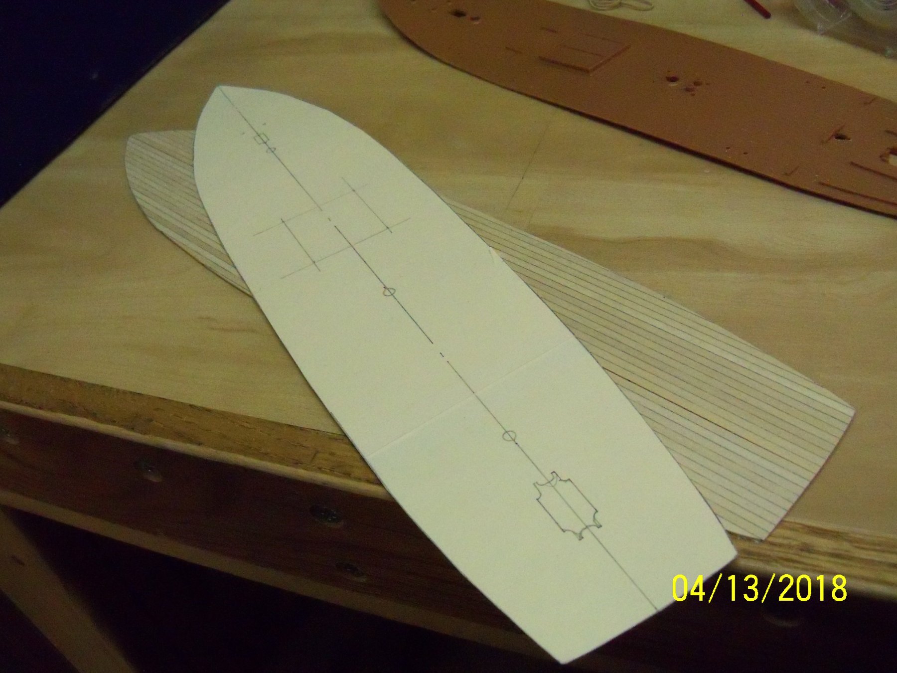
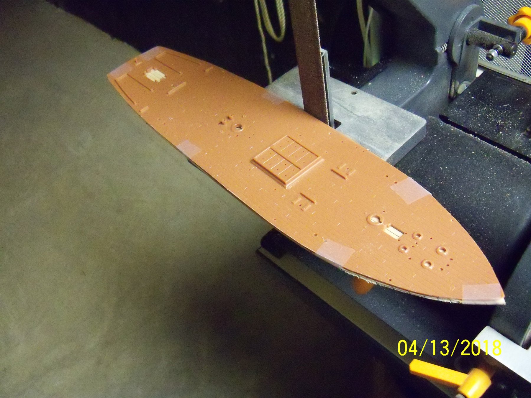
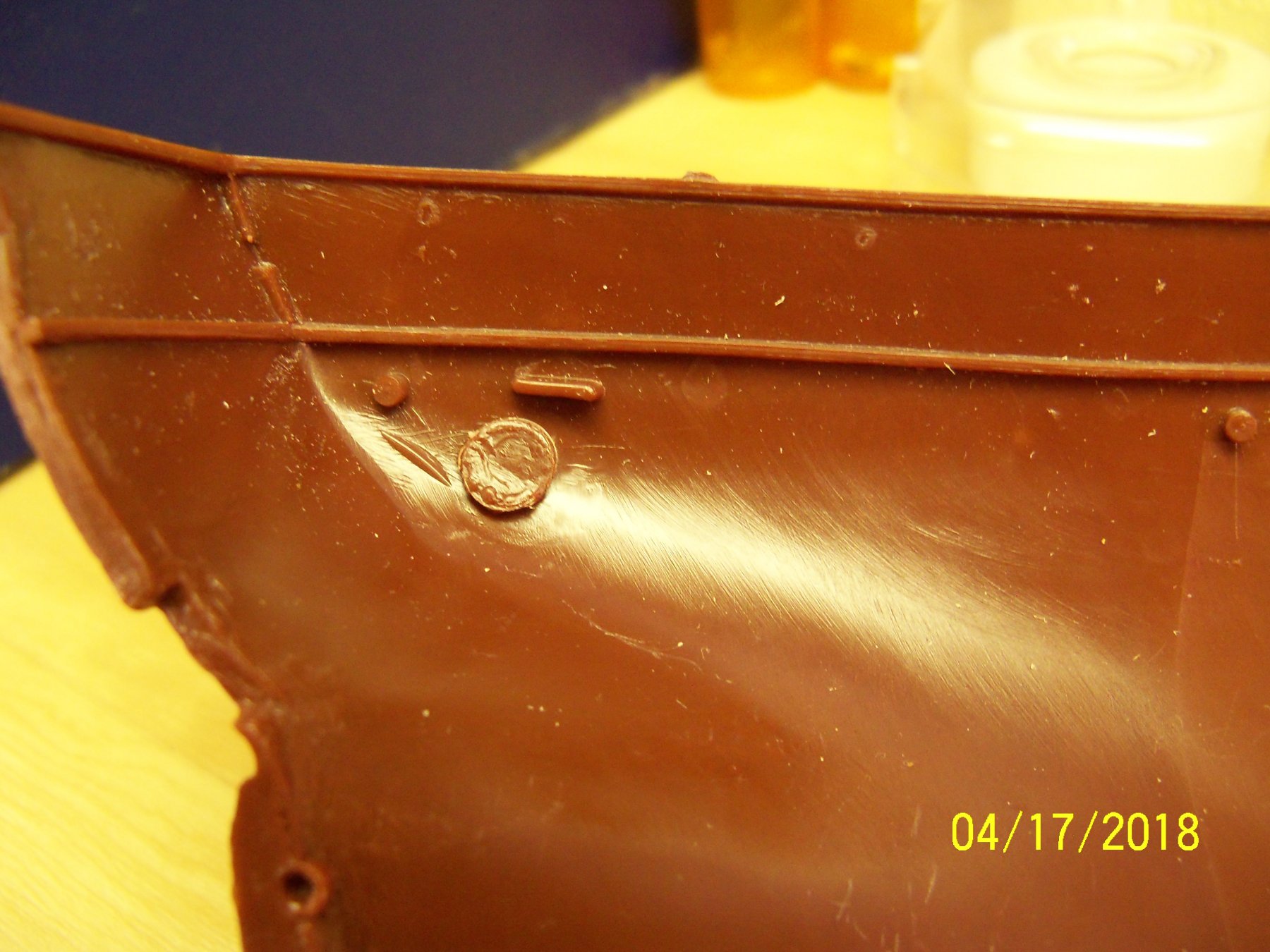
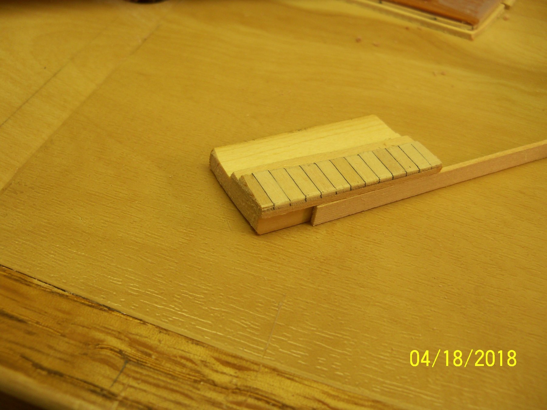
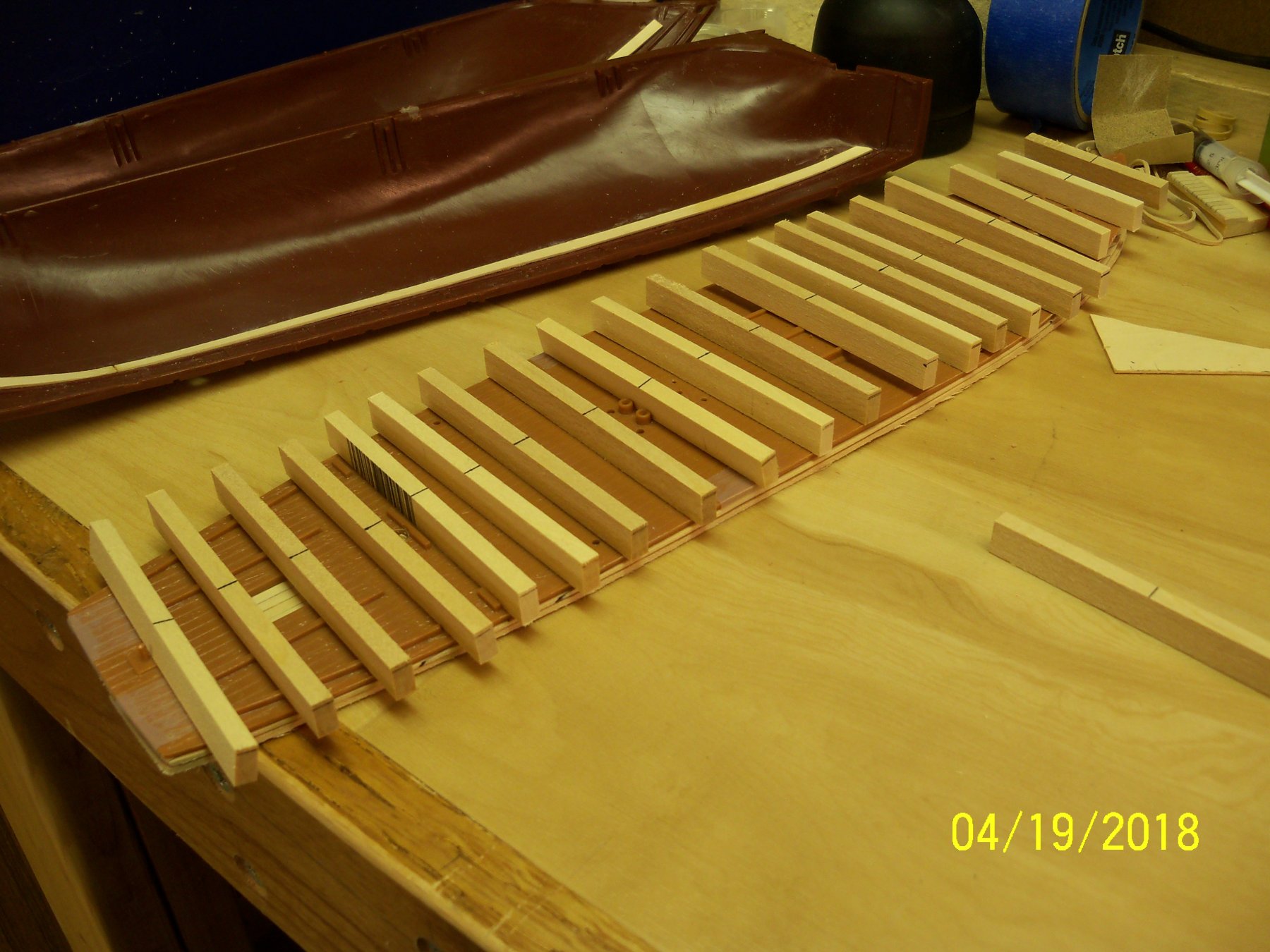
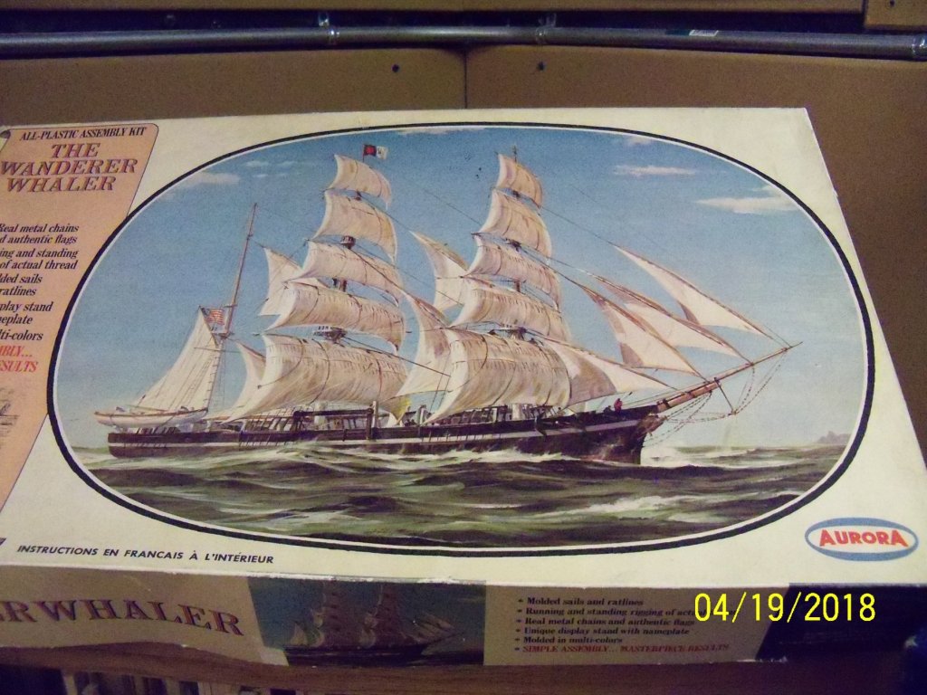
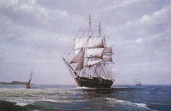
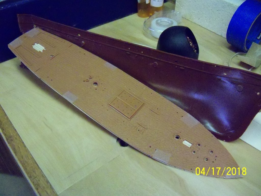
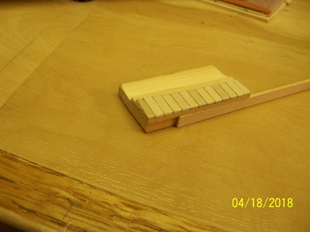
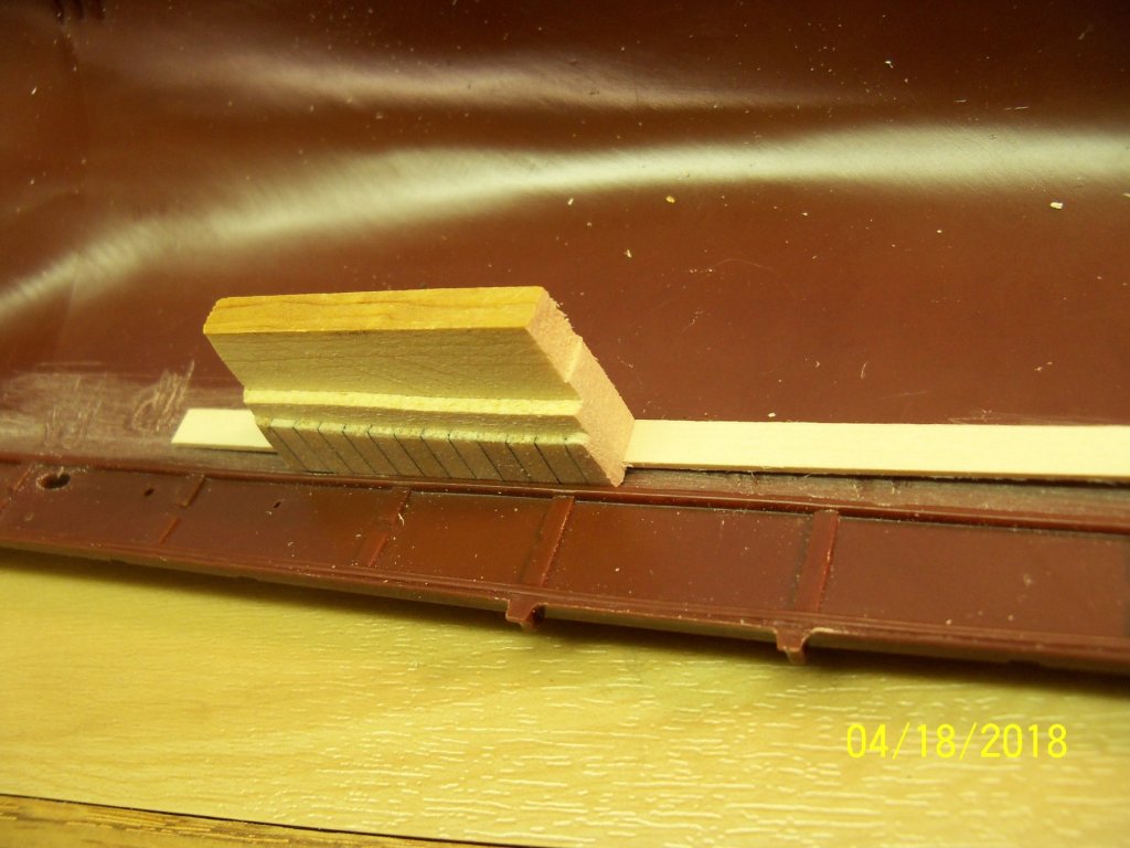
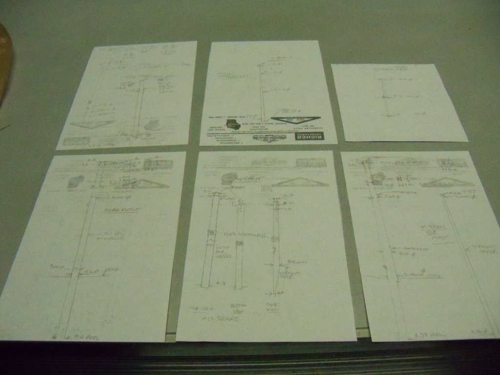
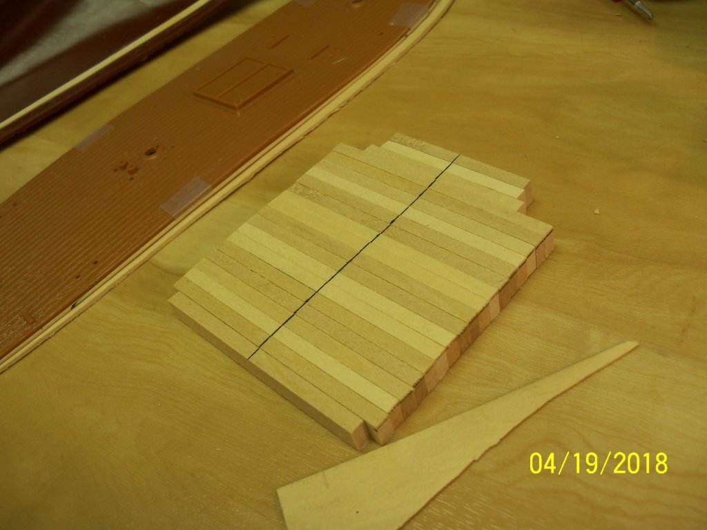
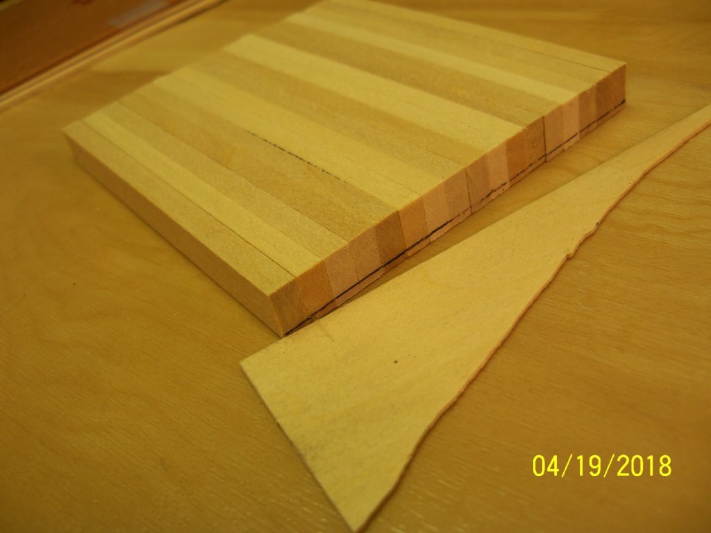
This model was just sitting on a shelf patiently waiting for some attention when a friend of mine saw it and wondered if I could build it for his office. While I am currently working on the MS Phantom, I thought I could do both and try my hand at making a build log for this one. I suspect that this method of model building is quite unusual, To tell the truth, I was not certain that this belonged in the kit built category, as the only part of the kit that is being used is the hull with all the rest being scratch built from wood and metal. My friend was actually interested in a wooden ship, but I told him that I could replace most of the plastic parts with wood. I told him I’ve done that before and he agreed that it would probably look better that way, as the kit had heavy plastic sails moulded right to the spars and the deck had a lot of the details moulded right on which he thought looked pretty bad. As I reopened the box to examine the kit I found that the instruction manual was missing! Luckily, I had built this ship before in wood and still had the blueprints from A.J. Fisher. The plastic deck was not very impressive with a lot of the details moulded on it, but it was a one piece deck so that would make it easier to use as a template to make a wood replacement. Before I actually started construction, I decided that I wanted to do a search in the internet for more details of the actual ship. One thing that really caught my attention right off the bat, was the fact that the real ship only had four sails on the main and foremasts and not five as shown both in the kit and my set of blueprints. These two pictures below show both the box art and one of the pictures that I found showing the ship as it was built. Discovering this, I decided to really do some digging to see if any other discrepancies were evident. There were a few, but nothing as glaring as the sails. Taking the plastic deck in hand, I traced the outline onto a piece of manila folder including the mast holes, marked the center line of the deck, and transferred the outline of the hatch as shown below. As the end of the hull was closed in and the tumble home of the hull sides was too severe to allow a one piece deck to be slipped into place, I decided that I would have to split the deck down the middle for it to be installed. I took two 3”x24” sheets of glued up 1/8” wide 1/32” thick decking boards that were glued up with black colored glue to represent the caulking joints and joined them together edge to edge with tape across the backside. Placing the manila pattern over the pair of decking sheets, I taped them together, being careful to align the center-lines of the pattern and the joint of the two decking sheets. I traced this outline onto the decking sheets and unassembled it to allow easier cutting of the rough outline of the two deck pieces on my scroll saw. After cutting, the next step was to carefully tape the rough cut decking sheets back together again on their backside and tape these under the original plastic deck. Once again, I was careful to align that center joint of the decking with the center of the plastic deck. This assembly was then taken to my belt sander and sanded close to the edge. I would sand up to the tape and re-position the tape as I went along. (This was necessary because the plastic deck was quite warped and once untapped; it wanted to spring away from the decking sheets.) At this point the assembly was taken to my drill press. I drilled all of the larger round holes right thru the plastic deck to assure that they would align exactly. (This was especially important for the heel of the masts to align with the mast steps on the inside of the hull.) I then took the whole assembly to my workbench and drilled all of the remaining round holes with matching small bits in a pin vice. Here is a picture below of my progress to this point. Taking a look here at the inside surface of the hull, you can see that the waterway was already moulded on and would remain. However, the projecting tabs for support of the plastic deck and the injection mold stubs would have to be removed. Taking my new battery powered Dremel, I ground off all of these unwanted projections and sanded them smooth to allow me to glue some 1/32”x 13/64” basswood strips to serve as a ledger to support some new deck support beams. I decided that I should make a 1/16” thick basswood sub-deck, as the decking sheet was very thin, so I cut up two sheets of basswood for the sub-deck similar to the decking sheet as shown here. (notice the plastic decking springing away from the tapped wood deck) Then I made up a spacing jig to help align the top edge of the planking to the underside of the moulded waterway. Taking short pieces of the decking and sub-deck for spacers, I glued them to a thicker piece of wood for a handle as shown. Here is a picture of the spacer jig in use. Using this spacer jig as a guide, I used some thin ACC to attach the 1/32”x 13/64” basswood for the beam support ledger and clamped it in place for it to totally set up overnight. While the hull was drying I decided to work on the upper structure. The first thing I did with the masts and bowsprit was to do a trial assembly without glue of all the components to see how they all fit together. Disassembling these assemblies, I drew up some dimensioned diagrams of all the components for making their wooden replacements. The lengths were all drawn full size and the widths were written out next to their locations. Returning to the hull construction, I cut 17 3 ½” long pieces and 4 shorter pieces of 3/8”x 3/16” basswood to use for the deck beams. The kit was designed (as most plastic models are) to have a flat deck, so I worked up a method of adding the camber to it. I marked the center-line of all of the beams on their top edge as shown below. The camber was scaled off the 1/6” scale A.J. Fisher blueprints and converted to the models 1:87 scale. This worked out to about a 1/16” slope. Flipping over the whole stack of full length beams, I shifted the full size beams up against a piece of 1/32” scrap wood (to account for the approximate 1/32” width of the pen point), and marked all of the pieces on both ends. I set the beams on top of the plastic deck to get an idea of how to arrange them. That’s as far as I’ve gotten so far, I will post more later on the shaping and installation of the beams.


- 107 replies
-
- 15
-
-
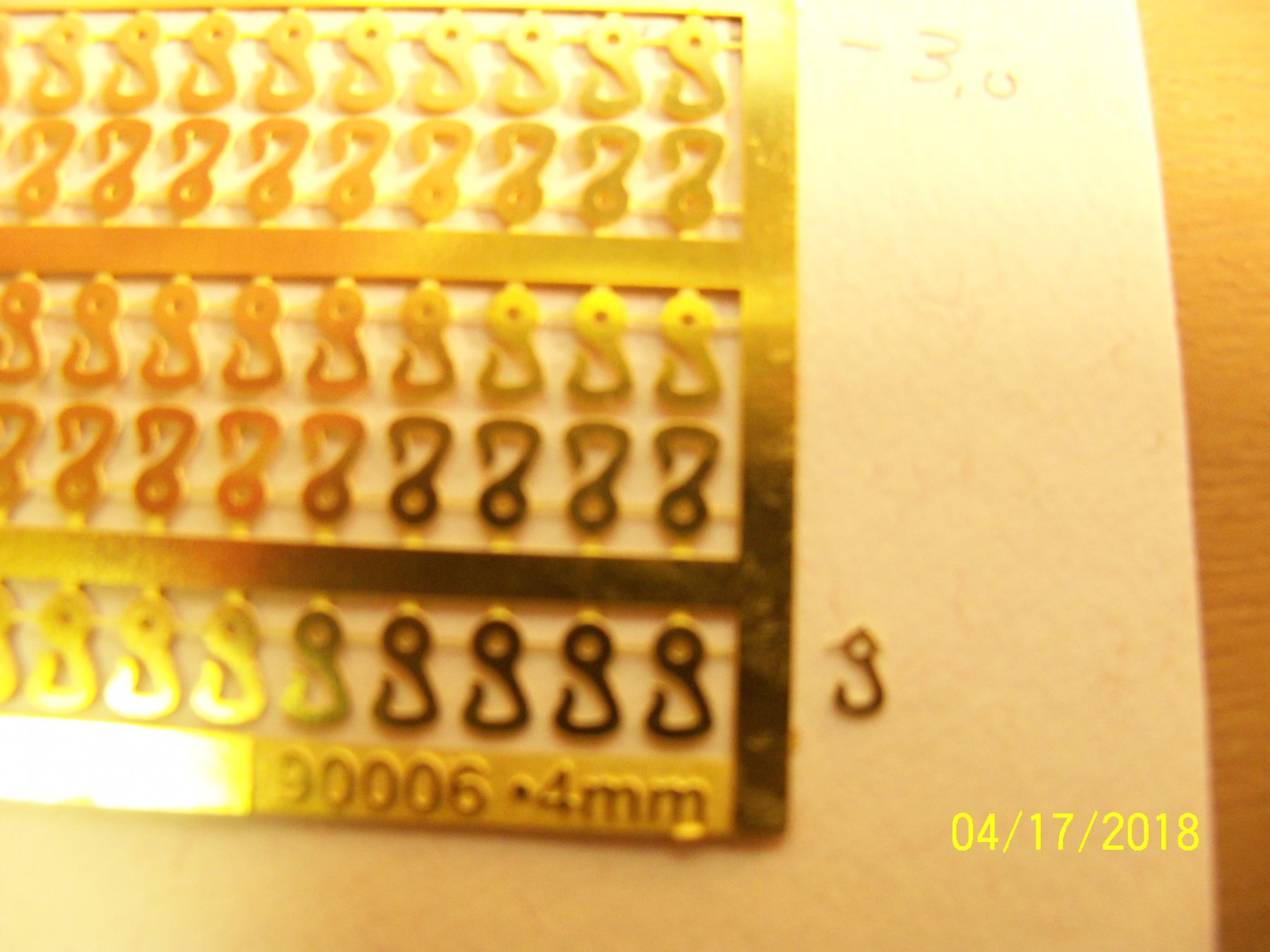
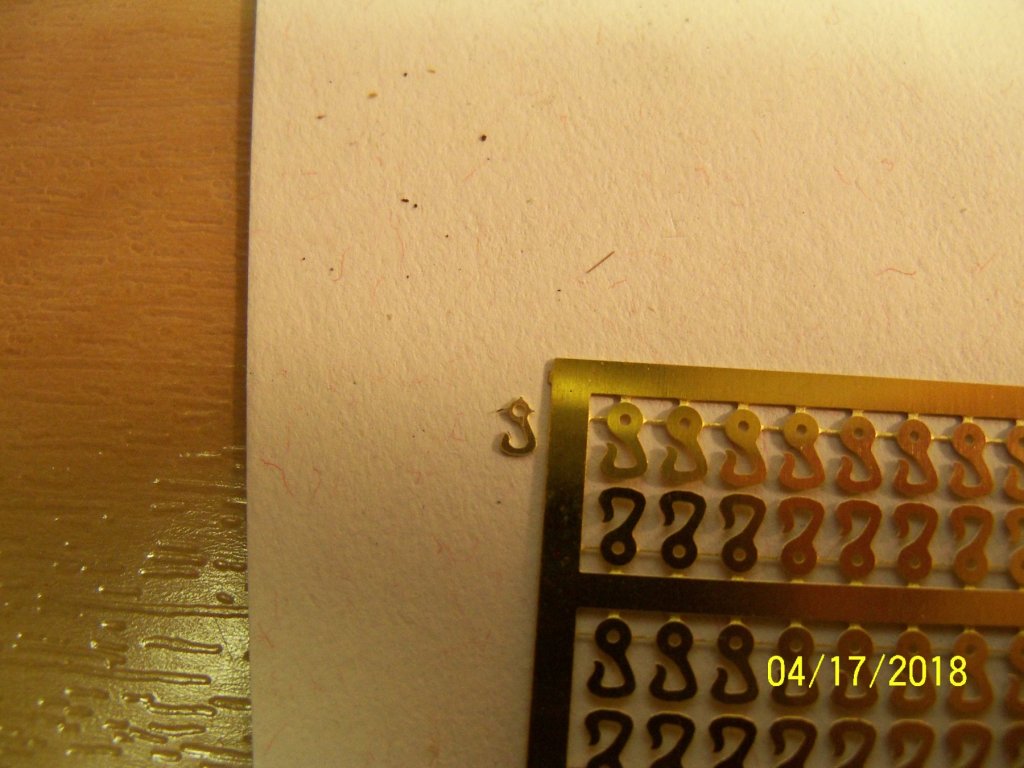
I just received my order of Chucks' rigging rope which included the 4 mm hooks. While I am very pleased with the rope, there seems to be a discrepancy with the hooks. The hooks look different than the 3 mm hooks that came my previous order of blocks. Obviously they were a different size, but they also were not the same pattern. (The rope hole for the 4 mm was actually smaller than the hole on the 3 mm hooks. A .5 mm drill bit would pass thru the smaller hook but could not pass thru the larger one.) If you look at the pictures above closely you can see that the hole in the small hook takes up almost the entire end of the hook while on the larger hook it takes up much less. Then I looked at the number stamped on the brass and found that while the 3 mm hook was labeled 90006.3mmA (as shown on the web site), the 4 mm hook was labeled 90006.4mm without the A. So apparently the A series must be different from the one without it. Hopefully the A series in the 4 mm hook size is still available for exchange. The larger hole size is the reason I need the larger one as I have to get a heavier line thru it. I would hesitate to try and drill the hole larger as that really doesn't sound feasible at all.

-
How did you get that realistic sag in the ratlines and how did you get it to stay put?
- 1,306 replies
-
- 7
-
-
- syren
- model shipways
- (and 1 more)
-
Those hooks that you're using look very good also. Are they fittings that came with the kit, purchased, or did you have to make them yourself?
- 1,306 replies
-
- 5
-
-
- syren
- model shipways
- (and 1 more)
-
Love your tall ship illustrations!
-
Perhaps a little feedback to Halinski is in order? I am sure that as they appreciate favorable reviews on their products, maybe they would also like being informed of the shortcomings of their products. Most of the good companies usually do. As you have mentioned they seem to have otherwise put out a great kit. I would send them your photos indicating the obvious error!
-
ModelExpo paint ?
BETAQDAVE replied to Senior ole salt's topic in Painting, finishing and weathering products and techniques
Thanks for the suggestion John. I took one of my Model Expos "hockey pucks" and was able to resurrect it! I now poured it into one of those plastic bottles with a cap that allows me to dispense the paint by the drop. Now I'm also planing on making it a monthly routine to shake all my paint bottles to try and keep them more usable. This saved me quite a headache as I had painted the inside of my Phantoms bulwarks quite some time ago, and now needed to paint the deck furniture to match, but found that particular paint color was now a hockey puck. My only two options seemed to be either try and match the paint with another brand (good luck with that) or to repaint the bulwarks with another paint that would match the new color. Somehow neither choice appealed to me, so thanks again for the suggestion! -
Well, let me be the first of many members to welcome you to the club. Like you, I started with plastic kits as did many of the other members, and was looking for something a little more challenging. We have a wealth of experience in our club, so if you need help with just about anything about modeling be free to ask as we would all be willing to help.
- 7 replies
-
- 3
-
-
- li
- lone island
- (and 1 more)
-
There was an article in the Ships In Scale mag. in the Jan/Feb 2012 issue by Robert Steinbrunn, where he used a sharpened piece of thin wall stainless steel tubing held in a pin vice. I think this system of wooden bungs was used on ships that used metal fasteners, so most earlier ships wouldn't have done this. He was building BlueJackets 1/48 scale model of the Smuggler. He said he made 3252 of these impressions, so it sounded like quite a job.
- 1,306 replies
-
- 6
-
-
- syren
- model shipways
- (and 1 more)
-
ModelExpo paint ?
BETAQDAVE replied to Senior ole salt's topic in Painting, finishing and weathering products and techniques
Perhaps MS should be doing that to their entire stock. -
ModelExpo paint ?
BETAQDAVE replied to Senior ole salt's topic in Painting, finishing and weathering products and techniques
You are probably right. The bottles allow way to much air in them, whereas the tubes allow very little. Some people say to try taking up that volume of air by filling them with stainless steel ball bearings, but when I received my Expo paint they were unopened for a couple of months afterwards but the sealed bottles were already like hockey pucks. -
While I like most all of you illustrations, I much prefer your tall ship paintings!
-
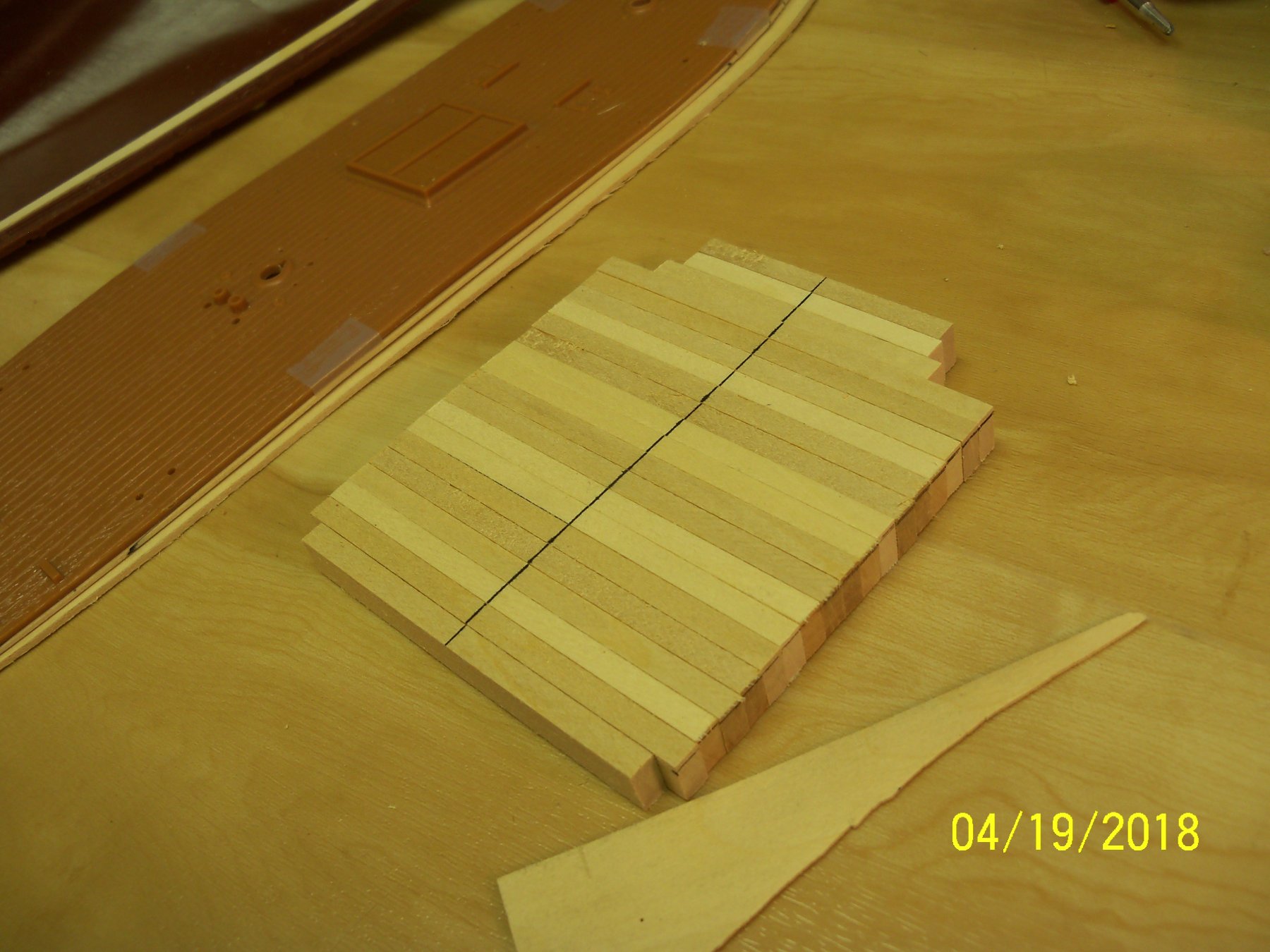
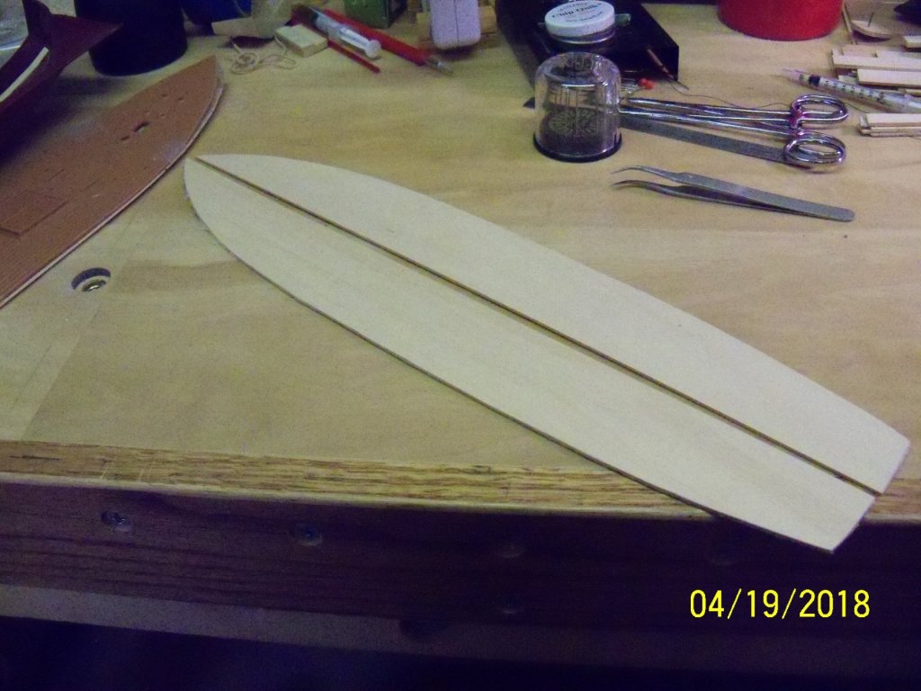
My 2 cents worth would be that scribed plywood decking just looks like plywood with lines drawn on it. Individual boards found on a real ship have much better definition than that! Having done woodworking for many years, I tend to notice right away that the wide grain pattern of the plywood crosses over all of the seams and that's a dead giveaway that it's just a sheet of plywood and not individual planks. If putting in individual decking boards looks like too much work there is still another option. I once modified the 1/96 Cutty Sark by Revell many years ago in which I replaced the plastic decking with some 3" x 22" sheets of .05" thick basswood decking boards that were 1/16" (aprox. 1.6 mm) wide glued up with black glue to represent the caulking. It was a little bit of extra work but I thought well worth the effort to eliminate the seams in the plastic deck and add that extra definition to them. Micro Mark still offers this product for about $17. (It's also available in 3/32", 1/8", and 3/16" wide planks.) For your reference I have also attached some photos of the deck of the Cutty Sark as it actually appears today. But, as it's your ship it really is your personal preference, so just have fun with it! As you can see, the decking is narrow and very light, so the 3 mm Mahogany would be both too wide (judging by the aprox. length of the feet of the tourists they must be about 6" wide, so @ 1:96 the planks should be about 1/16") and a poor color choice for decking but a good choice for the deck structures.

-
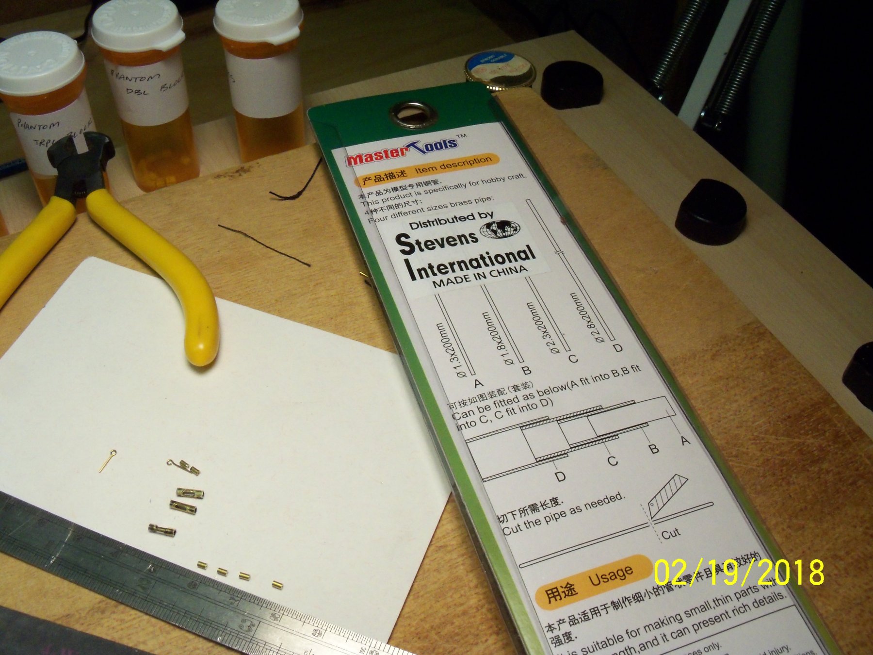
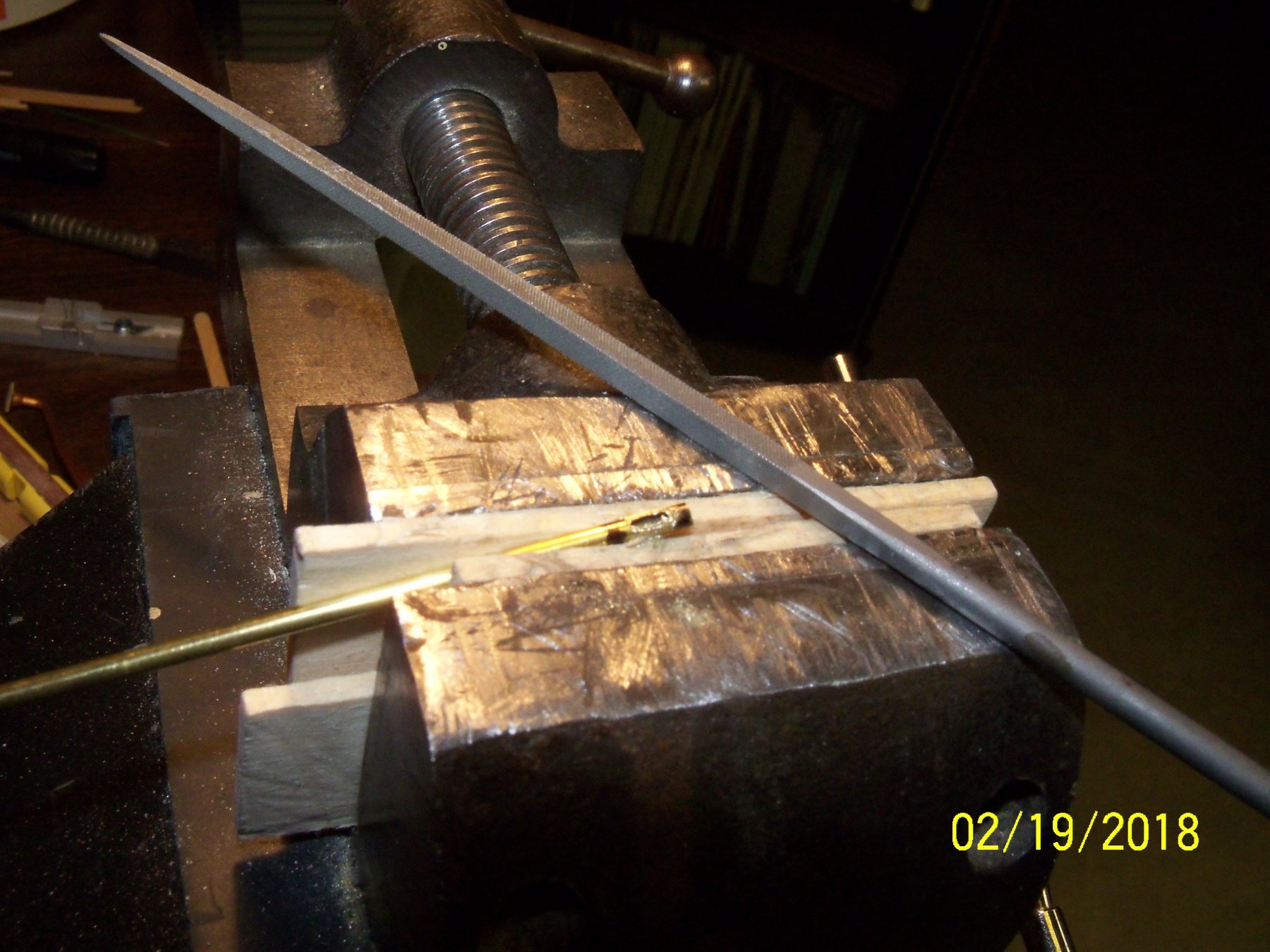
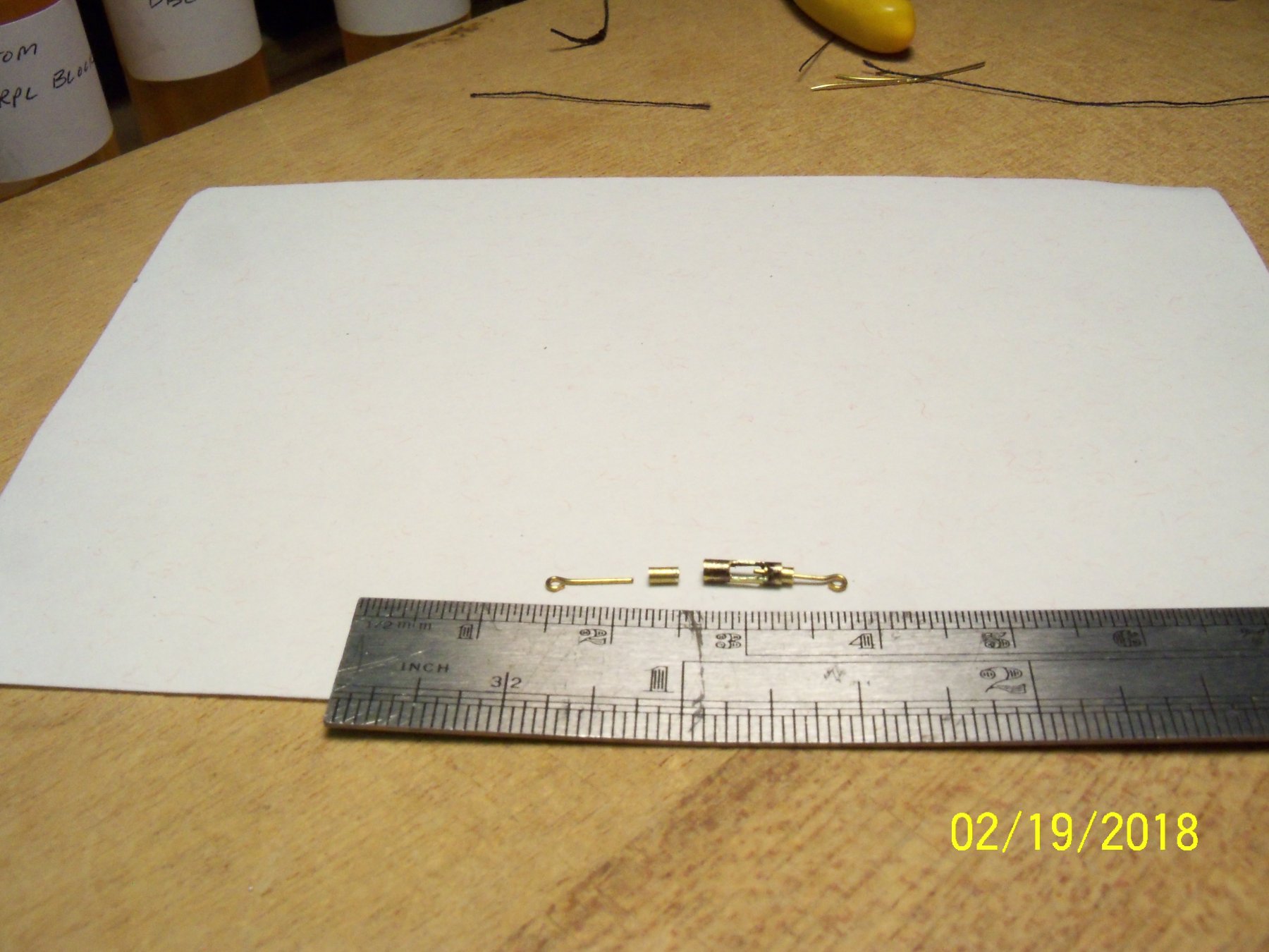
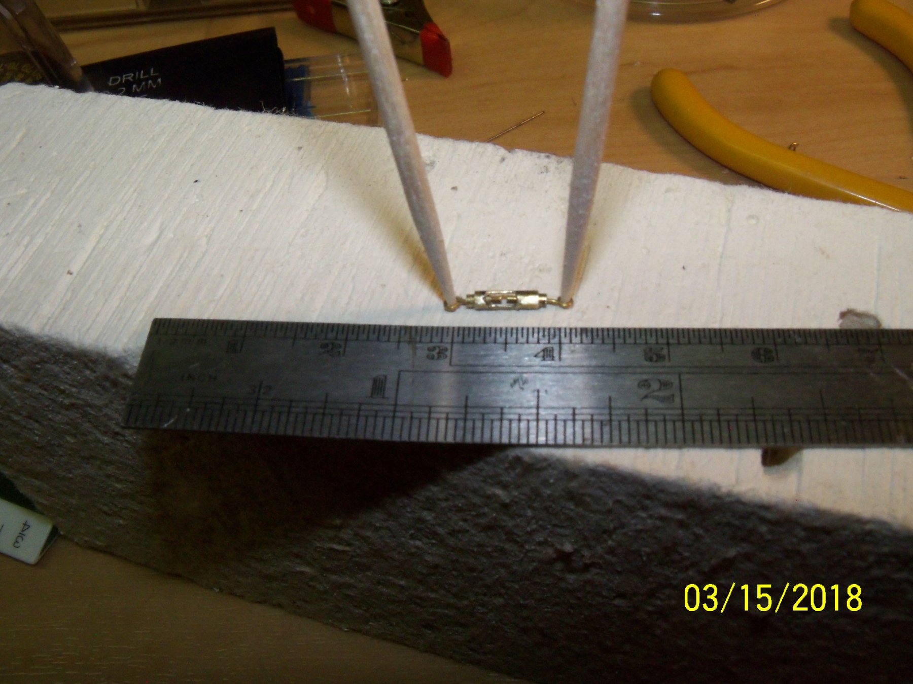
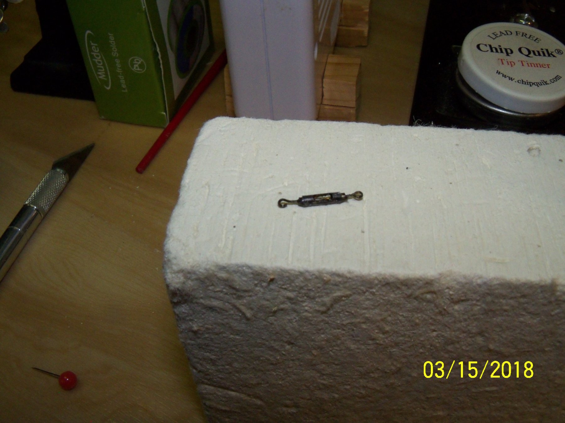
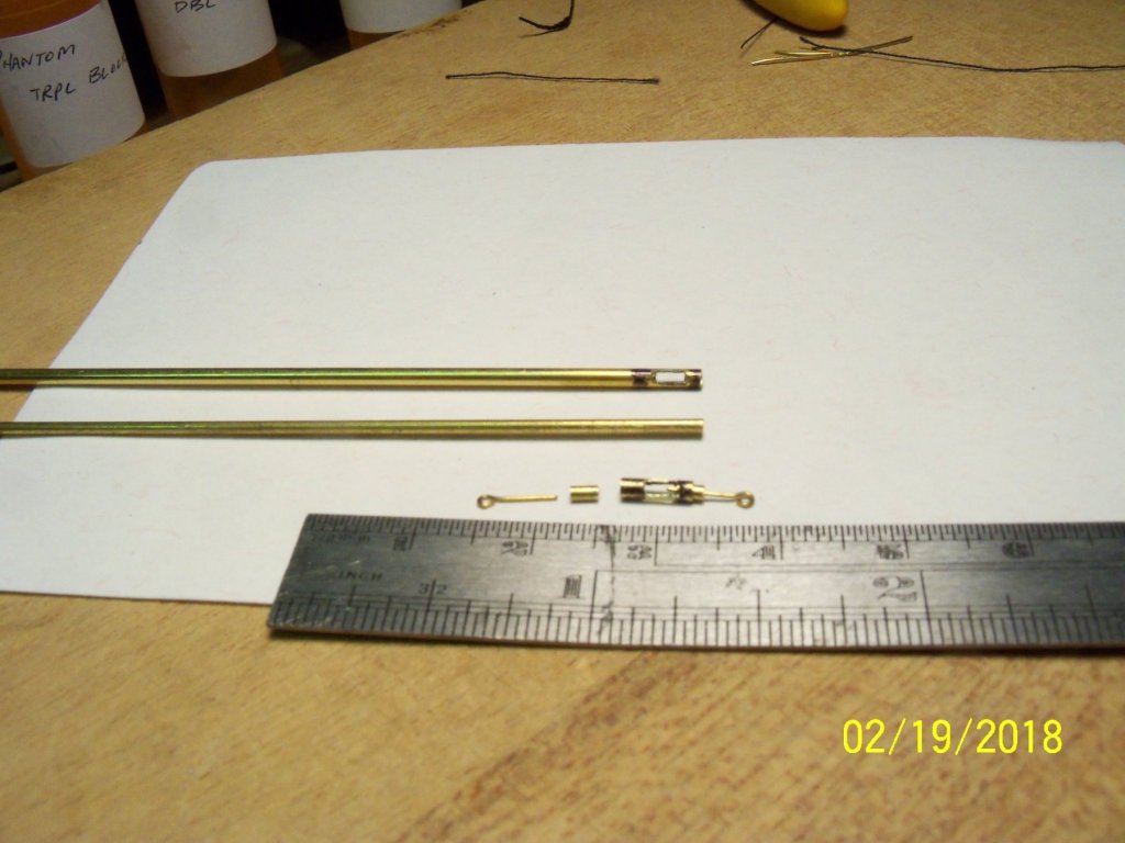
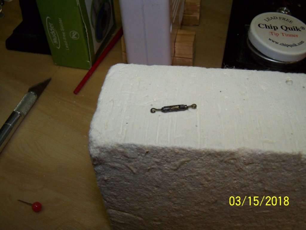
While working on my modified MS 1:96 scale version of the “Phantom” I found that I needed to make three very small turnbuckles. (They were referred to as stretching screws on the plan.) I had bought some brass telescoping thin wall tubing previously for making yard bands and thought up a way to use them to make a fairly realistic fitting. I took some 1.3 mm brass tubing that was just big enough to allow an eye bolt that came with the kit to slip into it. Then I used the 1.8 mm brass tubing (the next size up) that the 1.3 mm tube could be slipped inside of that for the main body of the turnbuckle. I marked the length of the 1.8 mm tube and the length of the opening with a felt pen. Taking the 1.8 mm tube to my vise, I cut out the open areas on both sides with a fine narrow file. I cut the 1.8 mm tube to length for the main body and cut a pair of short lengths of the 1.3 mm tube for the inside ends of the turnbuckle. Taking the five pieces to my soldering block, I applied flux to the shortened eye bolt stems and the outside of the 1.3 mm tube. The pieces were then assembled together and stretched out on the block with a couple of toothpicks stuck through the eye bolt holes to hold it steady. I cut some small flakes of solder and placed them at the ends of the turnbuckle body and applied my soldering iron to the 1.8 mm tube. After it cooled off I just cleaned up the ends with a fine file and blackened it. While the fitting still seemed a little large to me, I was quite satisfied with it. By varying the size of the components the size of the turnbuckles can readily be adjusted for various other scales.


-
Man alive Ed, you sure are doing an enormous amount of ironwork on this ship. Do you blacken the ironwork in place or before it's installed? If this is done in place, how do you prevent the woodwork from being stained? I have a hard time making the some of the complex ironwork fit in place only to have to remove it to blacken it and then reapply it. Your ironwork looks to be done quite neatly! The overall workmanship on this model is something way beyond what I can ever expect to achieve! (Maybe you should write a book about it someday.)
- 3,618 replies
-
- 3
-
-
- young america
- clipper
- (and 1 more)
-
That's not too surprising when you stop and think about it. Basically they're taking out all of the voids in the wood cells, adding a binder and putting it under tremendous pressure when it's rolled out, making it much denser. While one sheet of paper seems to weigh nothing by itself, just try lifting a ream of 500 sheets! Your ship is very well detailed for being a card model. The wood graining varies enough to make it look like individual wood planks. That's one reason that I like to build solid or built up hulls with individual planks applied to them. Hopefully your two feathered assistants don't get too interested in your ship and try to add their own touches to it. Our Parrotlet would like nothing more than to gnaw that paper up a bit. Hope you're feeling better soon.
- 1,035 replies
-
- 5
-
-
- royal katherine
- ship of the line
- (and 1 more)