BETAQDAVE
-
Posts
5,360 -
Joined
-
Last visited
Content Type
Profiles
Forums
Gallery
Events
Everything posted by BETAQDAVE
-

Ratline Making Tools
BETAQDAVE replied to acaron41120's topic in Modeling tools and Workshop Equipment
Although those Ratliners from Micro-Mark (It's basically a loom.) are available in three different scales, it's unlikely that the shrouds would align with any particular ships deadeye placement. -
I thought the same and although it was a bit pricey, I went to this site: Scaledecks.com and took care of the problem with mine. It's an actual wood product about the thickness of a heavy sheet of paper backed with a thermal fleece. Unlike some products out there that have a self-adhesive backing that makes aligning and placing the sheets very difficult, this backing provides plenty of surface for styrene cement to bind with and yet allows you to fine tune your placement. The pattern is very accurate and there is good contrast between individual planks which really makes it quite attractive.
- 398 replies
-
- 4
-

-
- cutty sark
- revell
- (and 2 more)
-
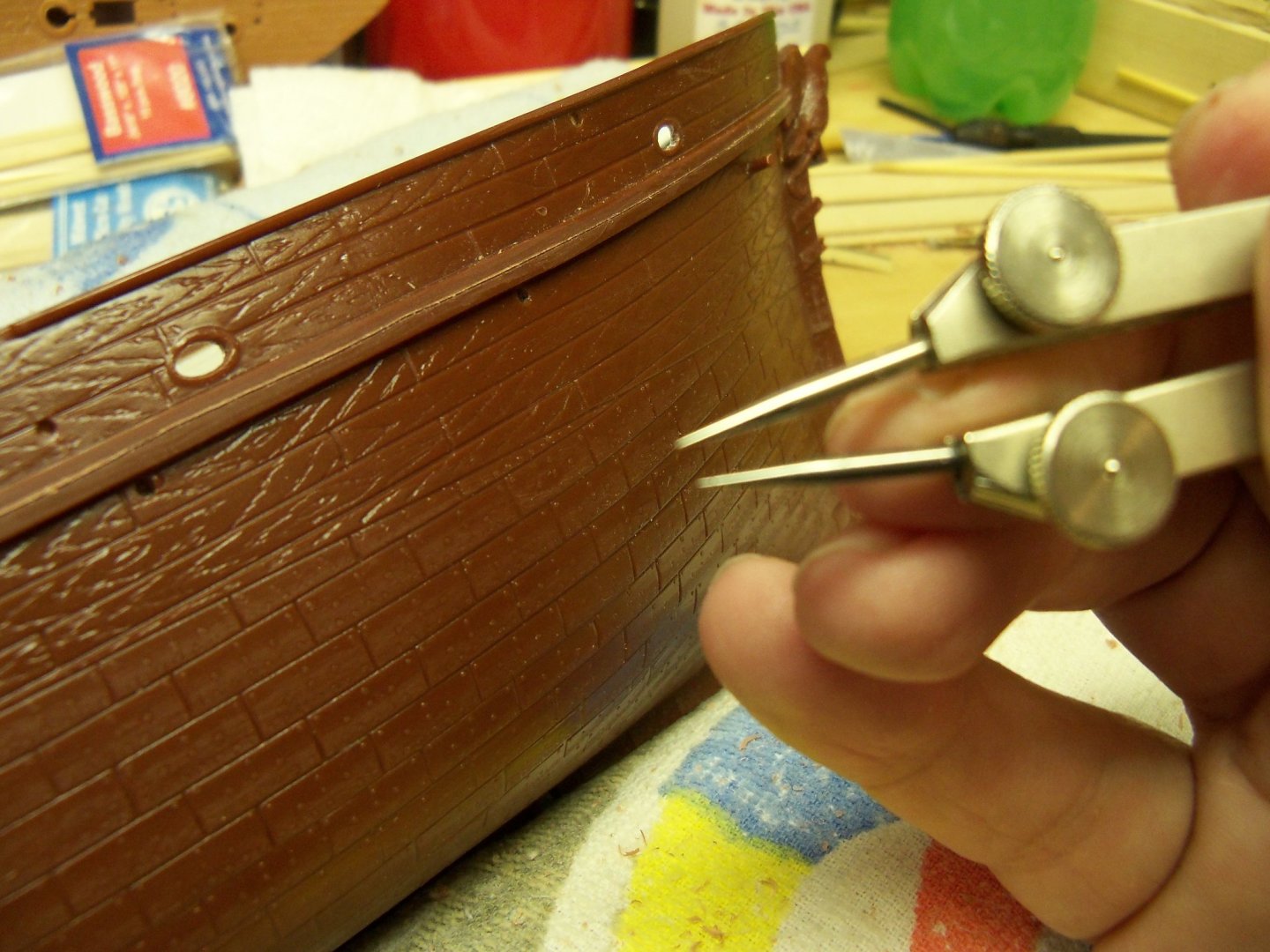
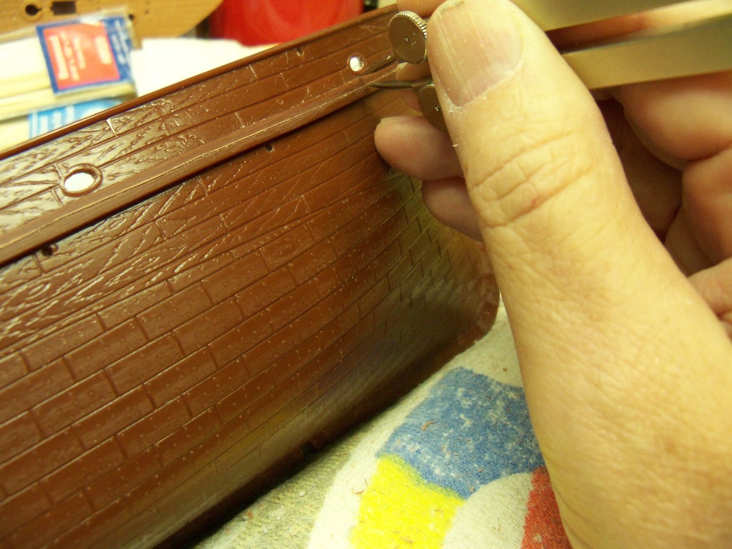
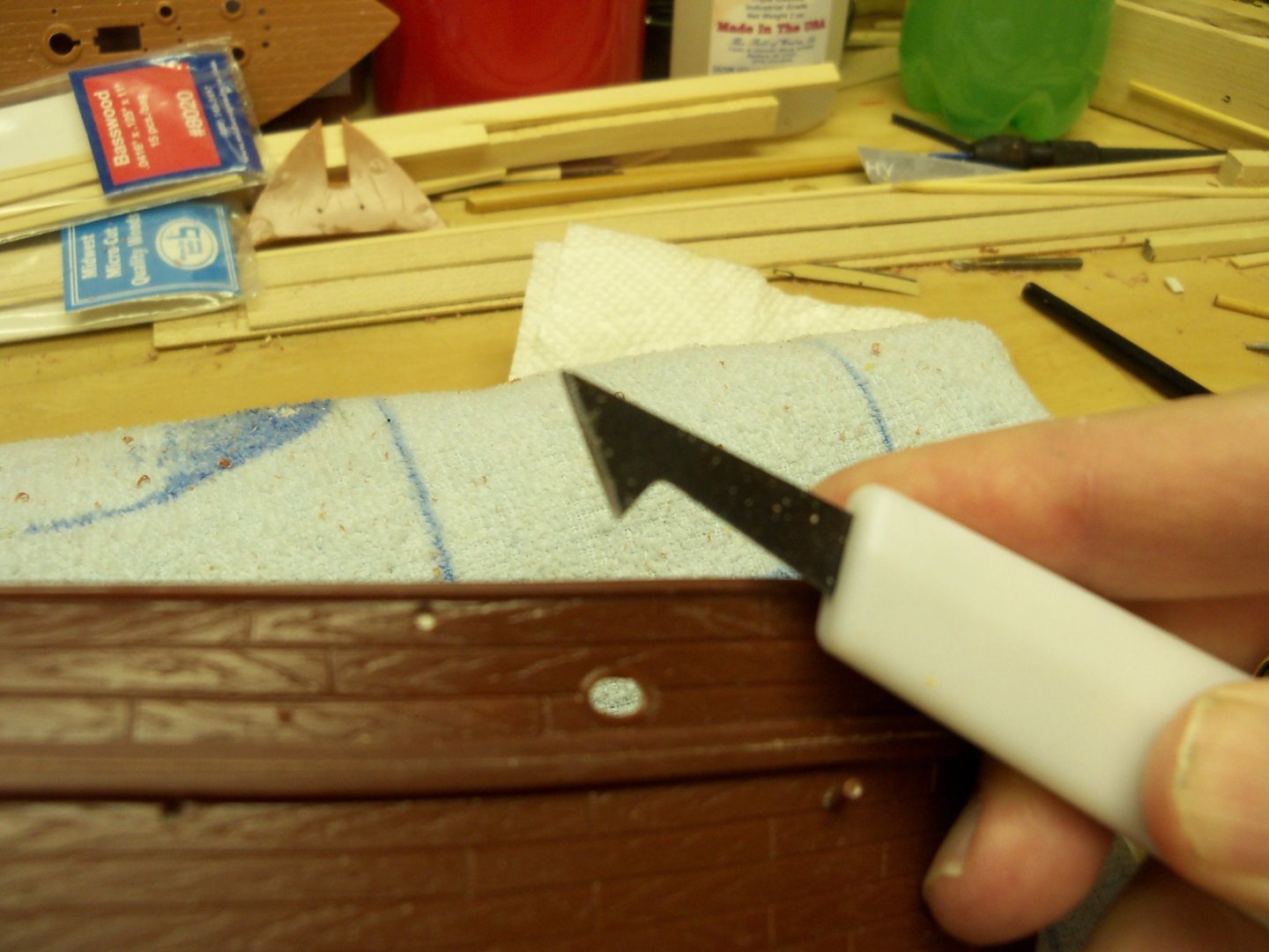
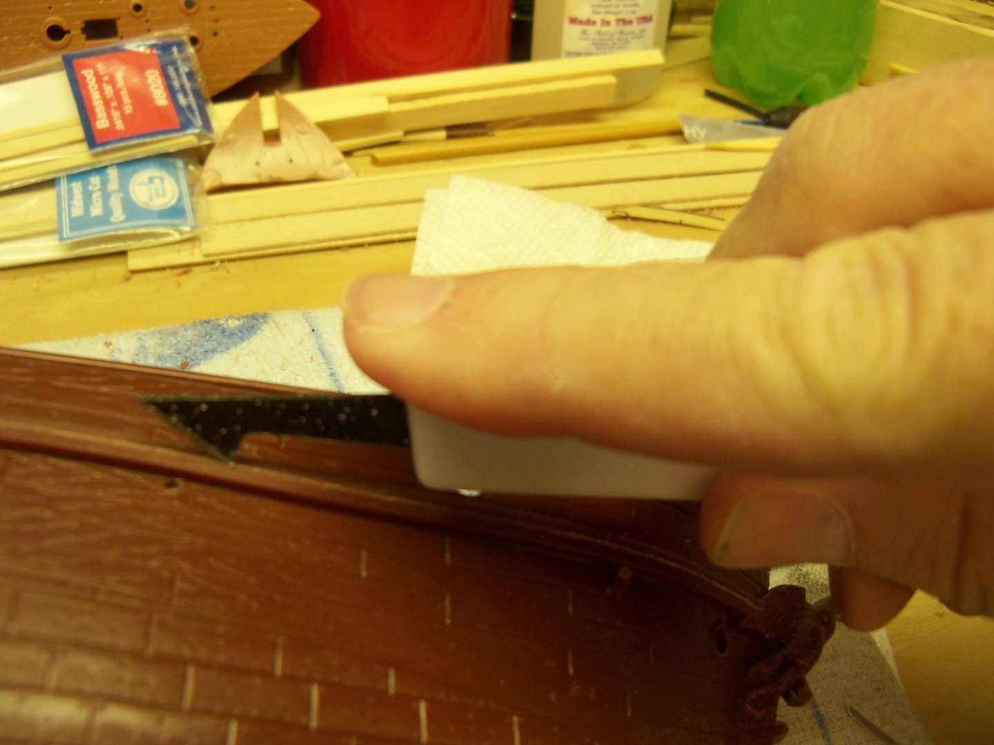
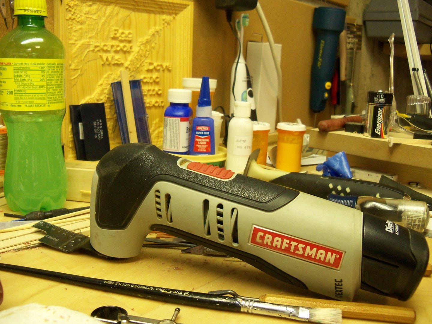
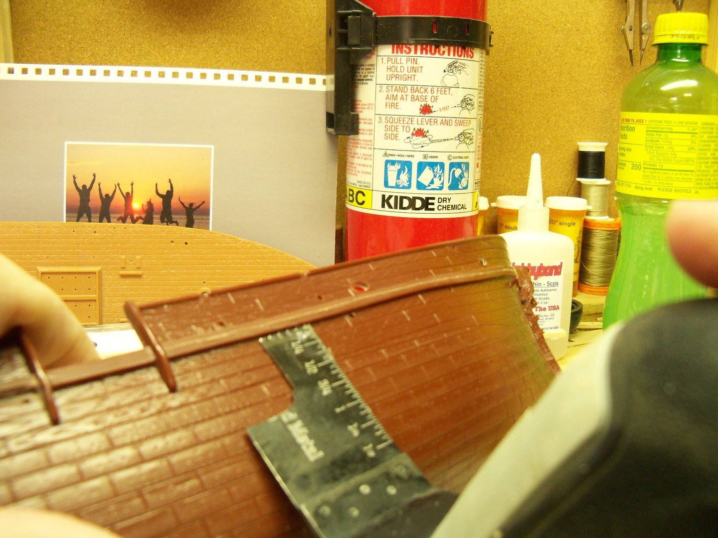
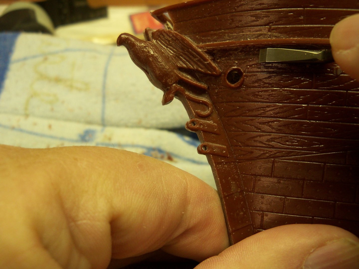
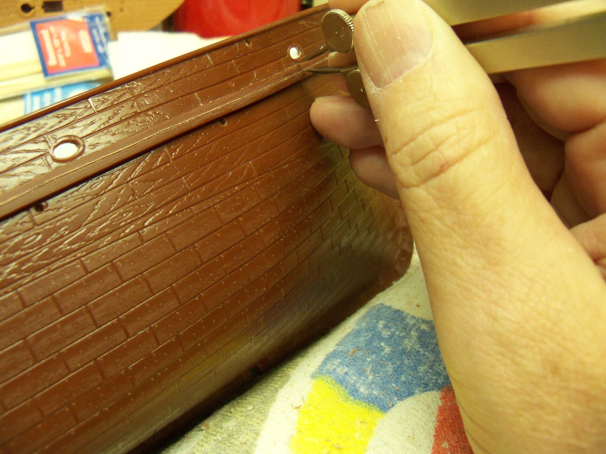
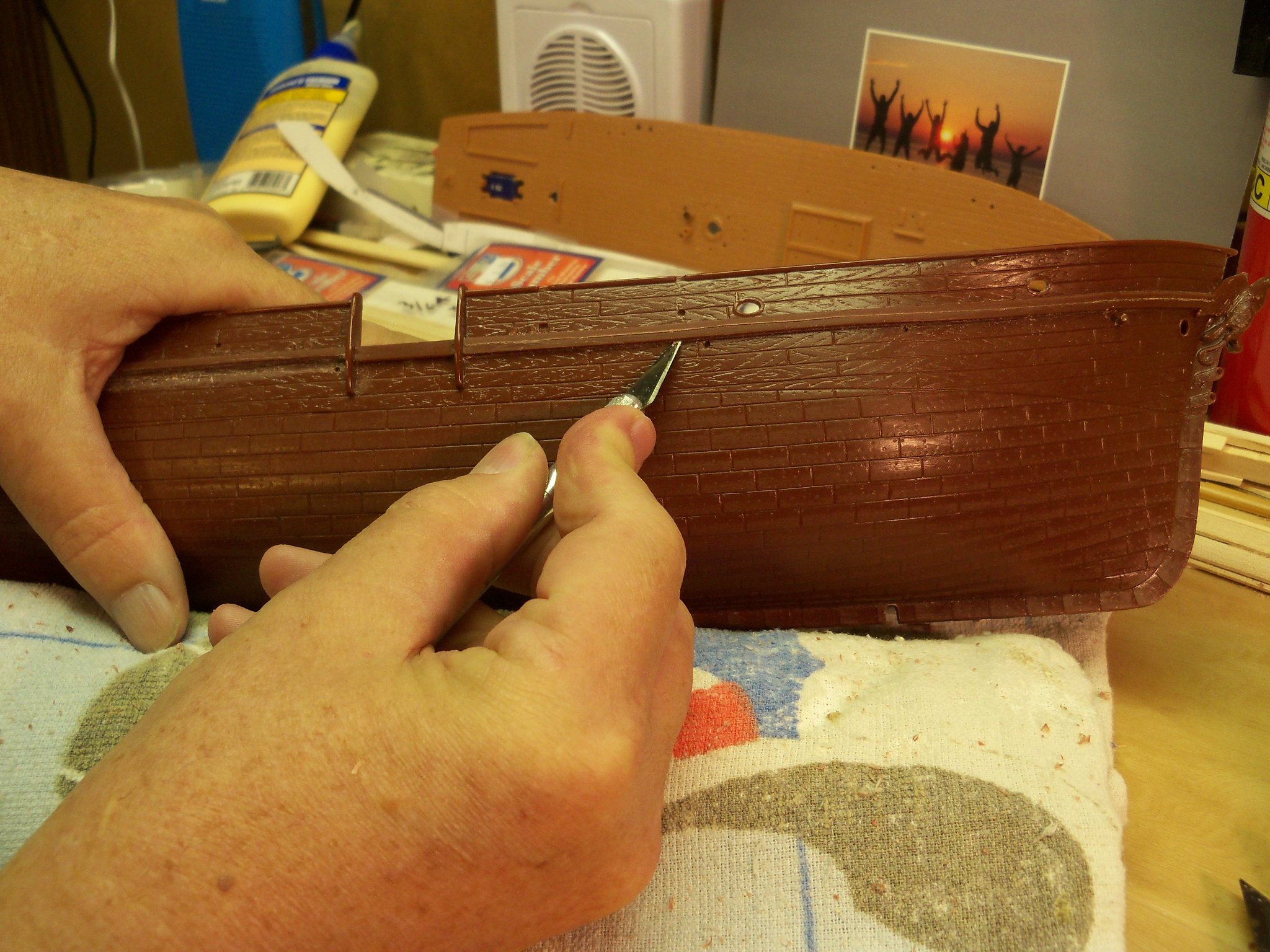
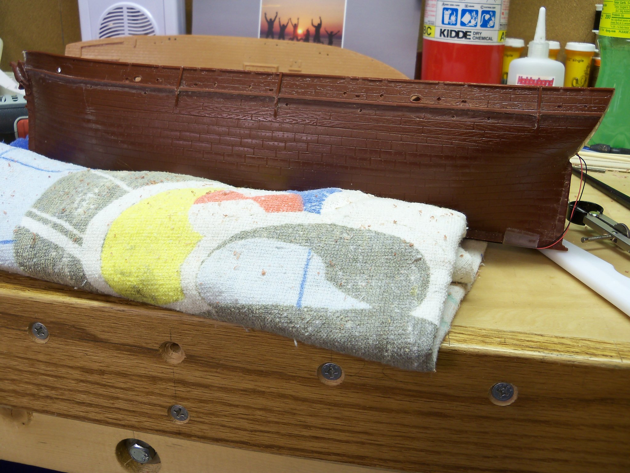
The main wale is shown in the photos as being the same thickness as the cap rail with a double beaded edge. Since the cap rail is going to be 1/16” thick, that’s what I’m going with. So the first step was to set my dividers at 1/16” with one point slightly extended to ride along the top edge of the plastic wale. Starting with a light amount of pressure, I scribed the short point along the entire length of the ships wale. (Incidentally, I worked on the port side first to work out this operation just in case it didn’t work out so well, because this would become the back side of the model.) Once I had a good line to follow, I switched to pulling the backside of an exacto knife with a #11 blade with the tip broken off. Gradually after a few more passes, the scribe line became deep enough for this plastic scriber to follow the line. Now I gradually increased the pressure and continued to deepen the scribe through the full thickness of the wale. This may sound easy, but it took at least 40 passes to do this on each section of just one side of the hull!! The next step was to chew off the lower portion of the plastic wale. Now I started working on the bottom of the wale, using a similar method of scribing a line along the bottom edge of the wale with that exacto knife. (The scriber handle prevented its use here.) Removing the bulk of the waste from the wale was pretty tough. At first I tried just using my 2MM dogleg chisel, but even though plastic would seem to be soft, it carves very hard. After much tough carving, I finally managed to finish the port side, but wasn’t looking forward to doing the same on the starboard side. So, I decided to modify one of the blades for this Craftsmen vibrating saw before working on the starboard side. With a hack saw I decreased the width of an old blade to make it more maneuverable. The blade basically vibrates with a very short stroke side to side. Following the scribed groove on the bottom of the wale I leaned the flat of the blade up against the hull. This really made short work of the majority of the waste without damaging the lower hull. (Wish I thought of this before doing the port side!!) However, some areas like here where the wale meets the eagle figurehead I still needed the chisel to finish it. This left just a bit of fine work with the chisel to clean up this modified surface of the hull. With a little filler and sanding, applying the foil tape should make all this work disappear.


-
As I was waiting for my elevator to be serviced recently, I spent some of my free time (maybe too much) trolling the Internet looking for additional info on the Wanderer. I came across numerous photos of the actual ship that I hadn’t come across before and unfortunately, to my dismay, discovered that a lot of the info I did have was wrong. That even included some of the details that I followed on my first build of this ship from my A.J. Fisher blueprints. Although to tell the truth, those plans didn’t supply all that many details to begin with. I had to use quite a bit of guess work since that was built back in the 60’s prior to the internet and this forum. It’s also evident that most of the models of this ship that are shown on the internet do not reflect the actual features shown on the photographs. One model even shows the height of the bulwark to be closer to shoulder height rather than waist height that is shown on the photos and the figurehead as a woman in a dress rather than the eagle that was actually on the ship! The kit from Aurora that I am working with is also especially deficient as far as the accuracy of those details, but the main form of the hull seems to be close enough for me to modify to be a closer match to the actual ship. For example, the kits tryworks show brick exposed on all four sides rather than the iron sheathing on the sides and back by the carpenters bench. And one feature that was seemingly important on a whaler that is totally missing would be the trypots to boil the blubber in! So, this will be one major rework. Another detail that is quite a departure from the actual ship is fact that the anchor chain locker is located closer to amidships rather than right at the windlass as indicated on both the plans and the model kit. So I will now need to modify the deck to relocate those pipes. The main whale on the model is grossly oversized and will also require some major revision by reducing its size and changing its profile to show the double beaded edge that was on the actual ship. Luckily I didn’t paint the hull or mount it on the ways yet as this will take quite a bit of manhandling to remedy. Obviously the planking appearance will change, but then it will be covered with the vinyl foil tape anyway. Some areas at the bow and stern require an additional topgallant rail and cap not shown on the plans, so the planking will need to be consistent. To maintain some semblance of historical accuracy that is important to me, there will be many other details too numerous to mention here for me to modify. It looks like the project completion date will be getting extended, but I would not be satisfied with the model if I didn’t do them. Installing the finish deck will be on hold for a while until I figure out some of the other modifications that will need to be done first. The first revision will be correcting the main wale, and I expect that to be quite a chore.
-
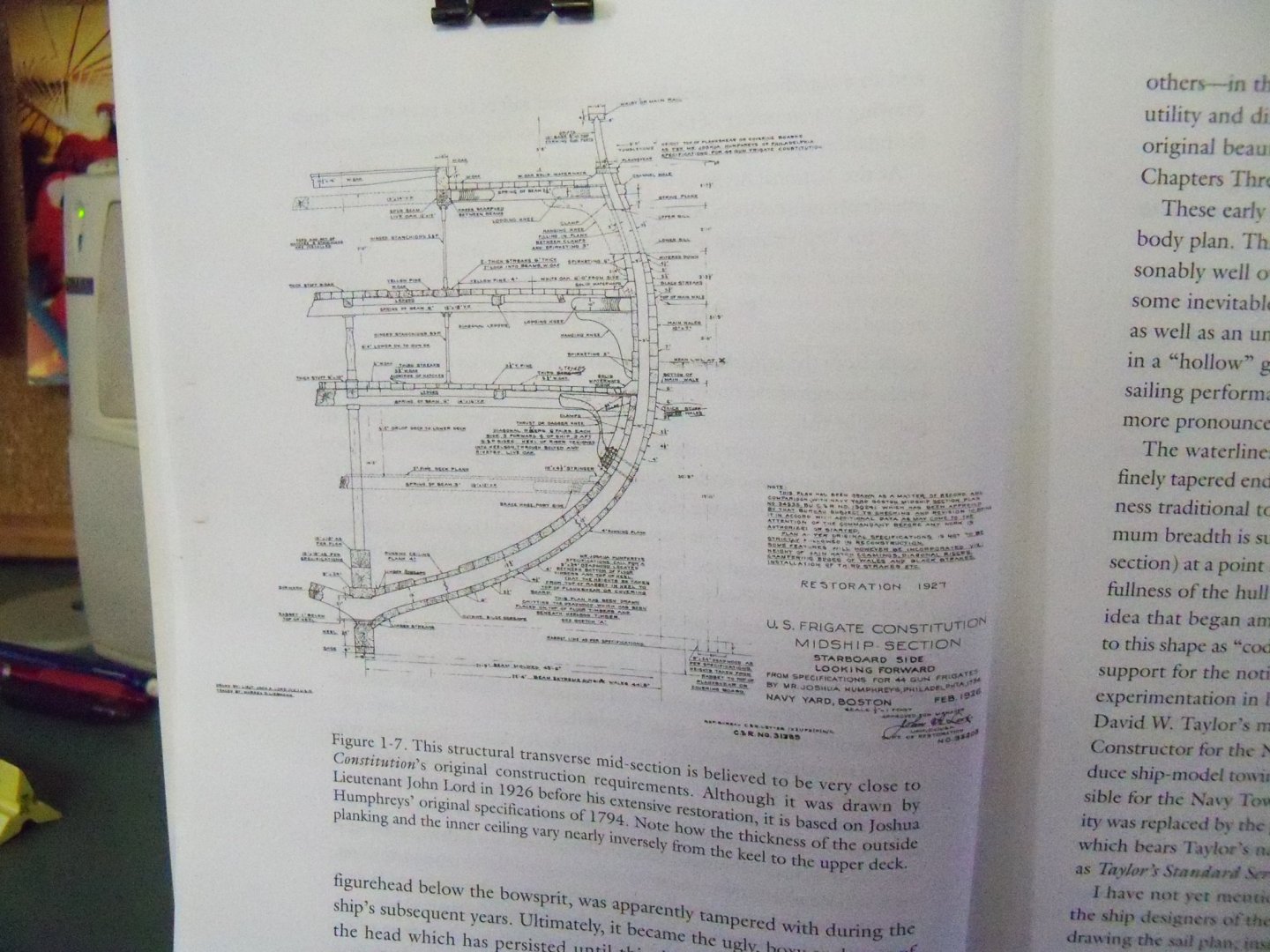
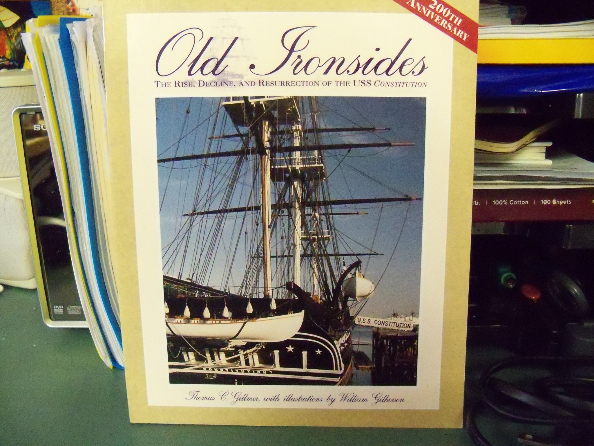
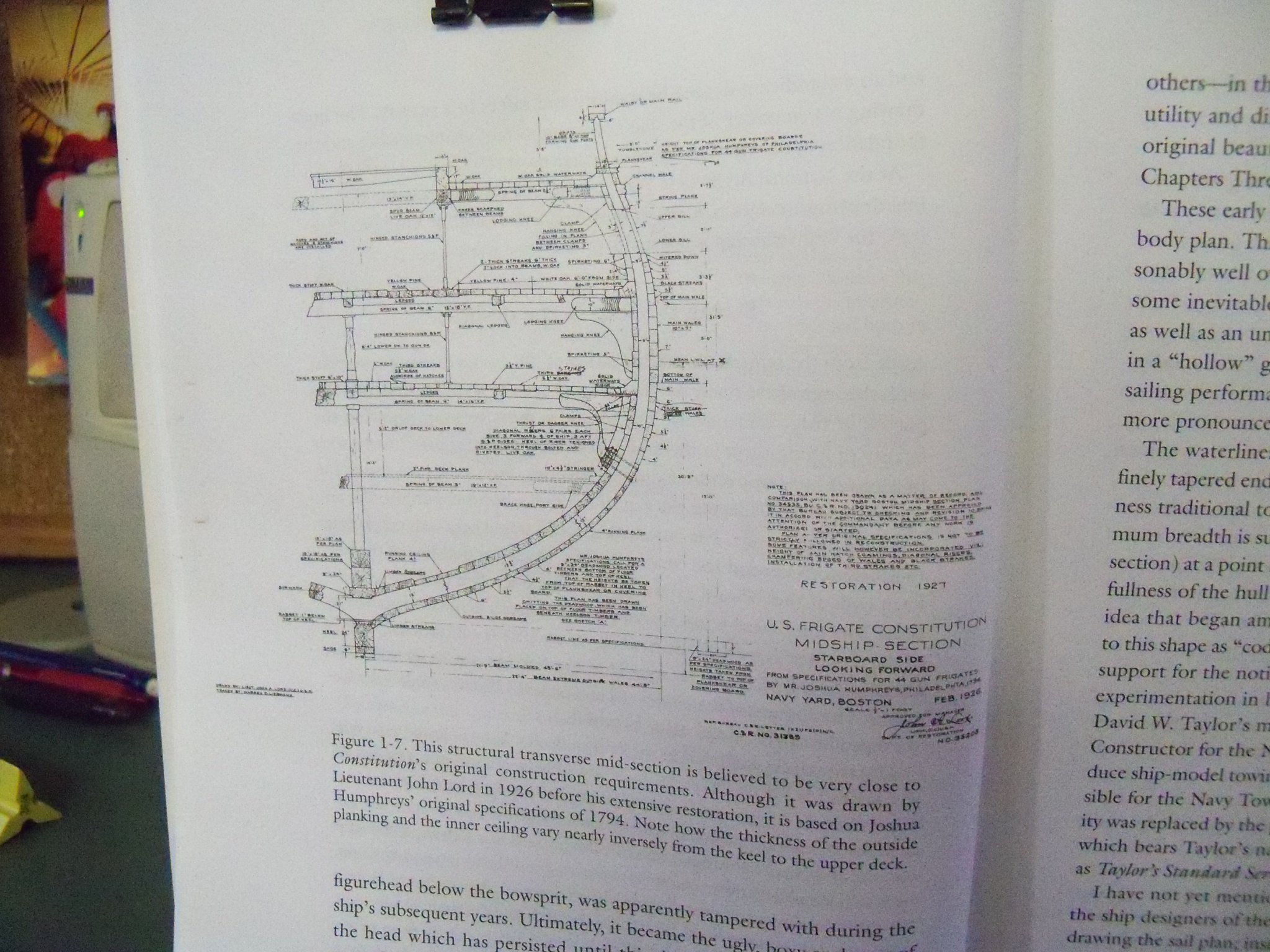
How about this paperback book that was put out when the Constitution was celebrating her 200th anniversary from her launching in 1797. This book covers her from her design to her present state of preservation, including all the major and minor reconstructions. It includes detail drawings like this throughout. There are also several color prints of her in action including her living room sized main fighting top. At a cost of only $22 I found the 239 page book to be a very informative guide when I built the Revell version that's currently still in drydock after a fall that pretty much dismasted her when impacting the floor of my garage. I've never repaired her, but didn't have the heart to throw it out as I still may fix her up. Maybe someday.......


-
Looks like a good poster for Ducks Unlimited. (A local local wildlife preservation organization.)
-
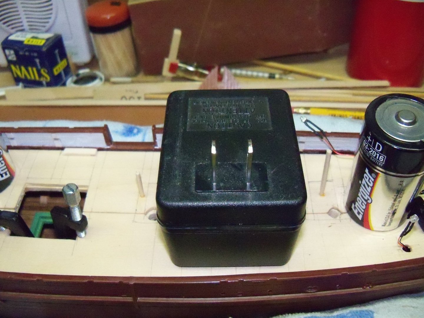
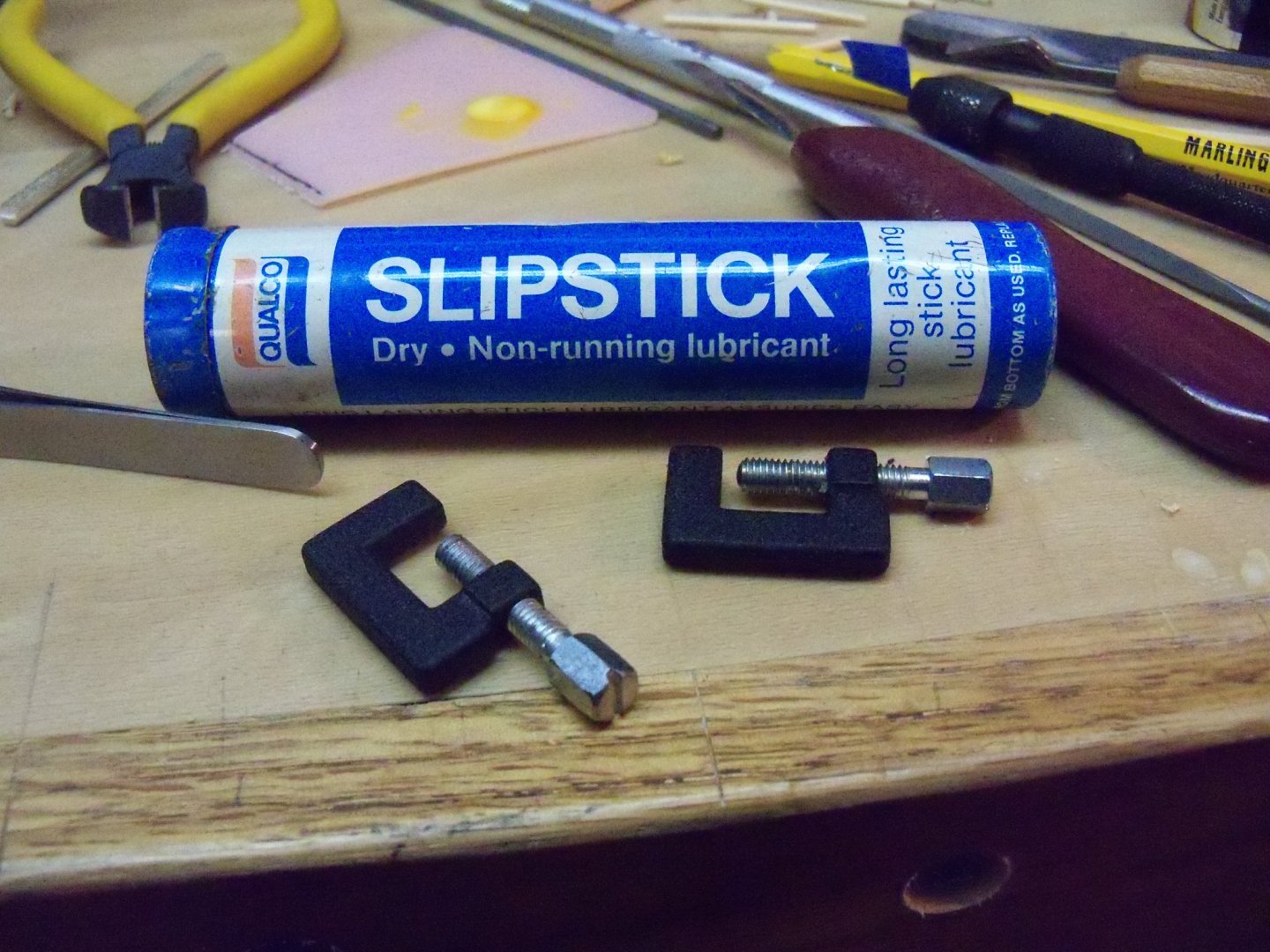
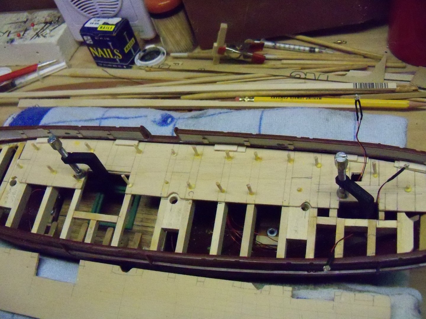
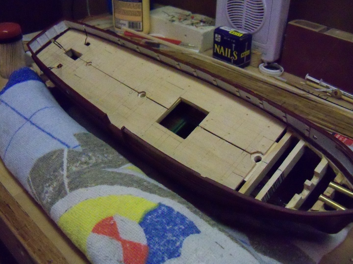
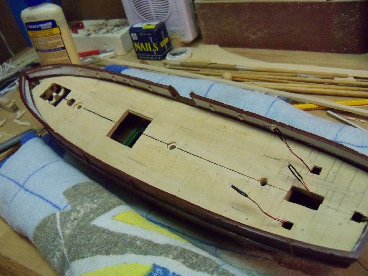
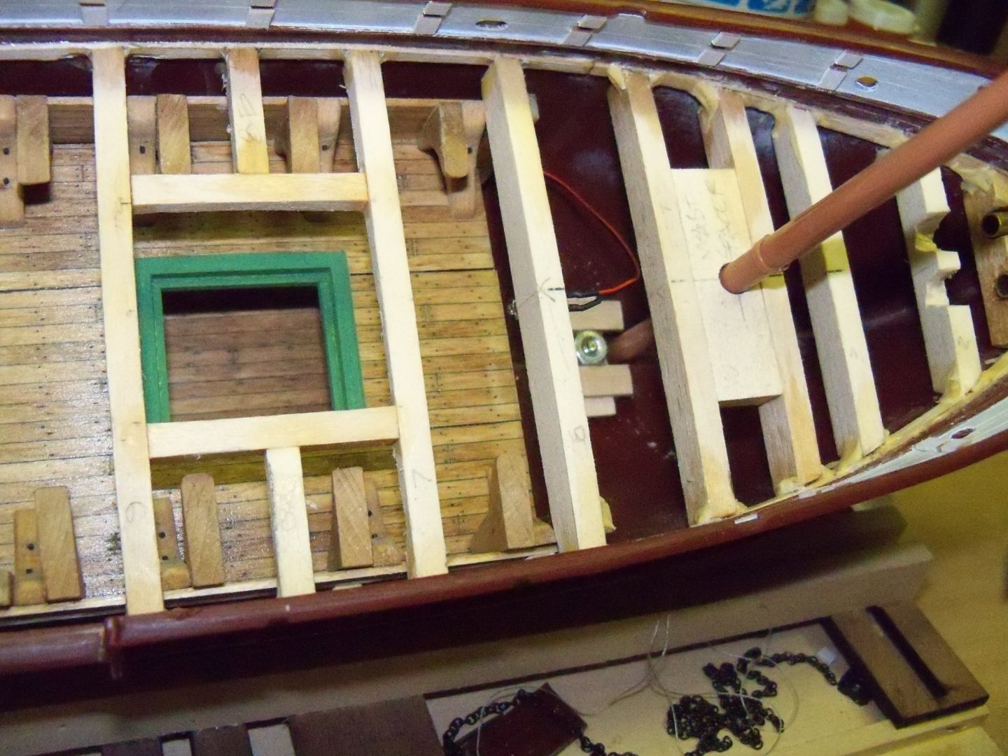
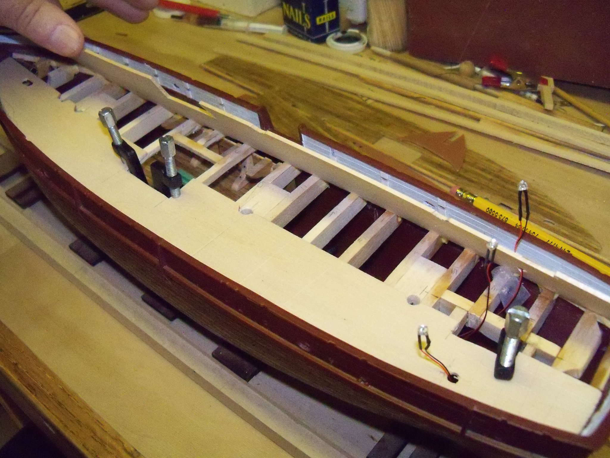
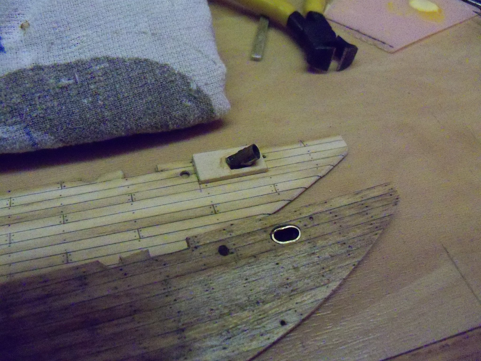
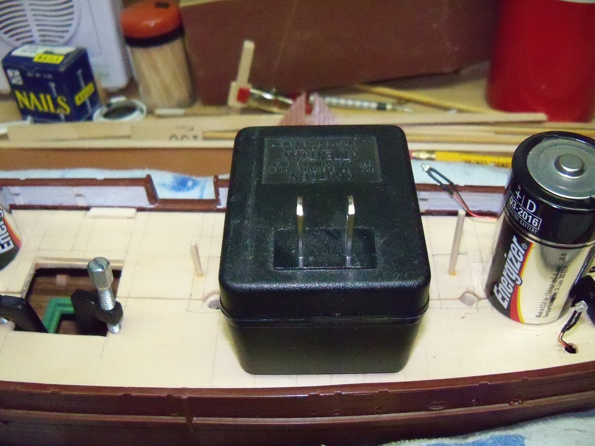
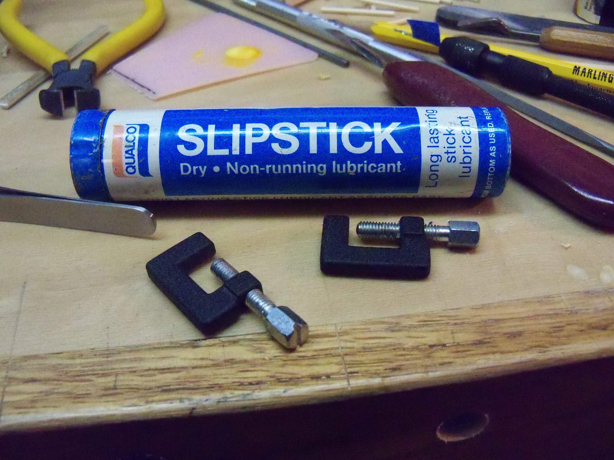
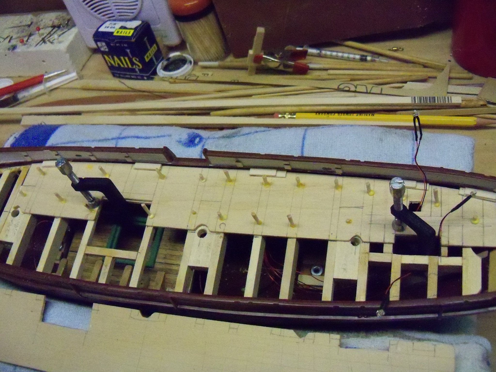
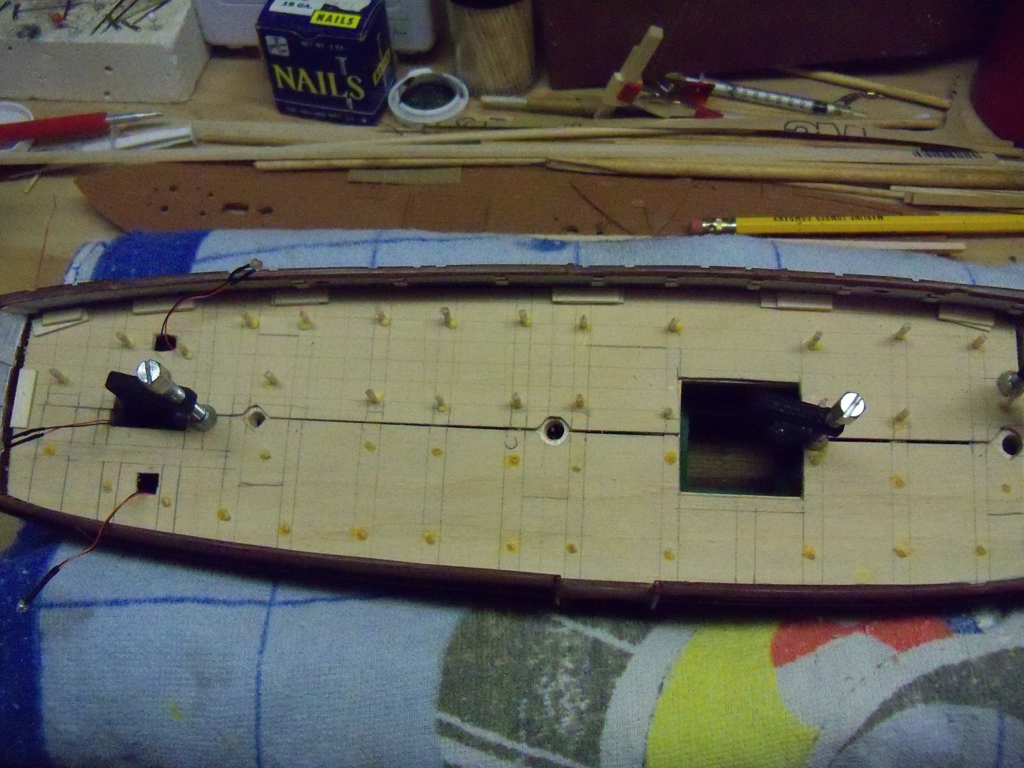
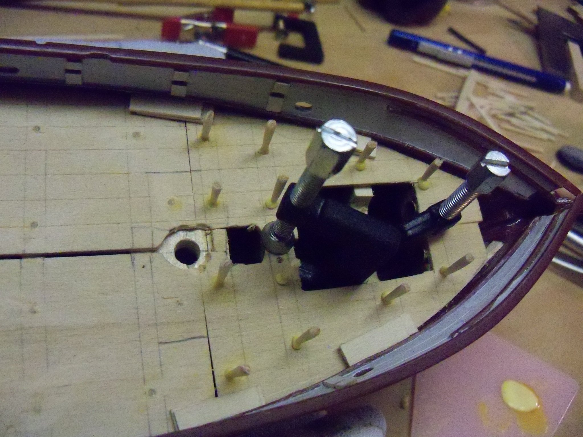
What‘s that saying about the best laid plans of mice and men? Oh yeah. I decided that the next step now had to be changed from painting the copper hull to installing the wooden deck. Due to the manhandling of the hull that would be necessary while installing the decks, all of my masking now had to be removed. Oh well, better than risking damage to the paint job. The false deck needed to be installed first, but clamping the false deck down presented quite a problem since it curved front to back and side to side at the same time and the bulwarks were in the way. Because the glue needed to be spread out on all of the deck beams, by the time the glue was spread, there wouldn’t be enough time to set all the clamps before the glue set up. So, rather than trying to glue the deck directly to the beams, I ended up pinning it down. (That’s where the ends of those tooth picks used for the pegs in the last posting got to be used up.) Taking the starboard side of the false deck in hand, I lined it up with the centerline of the ship and clamped it in place. I put tic marks along the centerline to mark where the edges of the beams were located. While the starboard side was still in place, the port side was fit in place and the tic marks were transferred to that side also. I also cut small holes in the decks where the wires for the cabin lights would be located. At this time I needed to figure out how I was going to fit the finish deck in place with the hawse pipe fittings attached to the bottom side of the deck, since once the deck was attached I would no longer have access to the inside of the hull. My solution called for separating the bow ends of the false deck from the remaining deck to make things easier to handle. Once the bow ends were separated, a section of the false deck surrounding the pipes was cut free and the remaining bows false deck was cut just a bit bigger so that when the finish deck was attached it would allow some extra clearance. I fit the pipe through both the hole in the false deck bow section and the bottom of the finish deck, and glued it in place with medium CA leaving the pipe flush with the top surface of the finish deck as shown below. The false decks were removed and the tic marks were extended across the top surfaces using my thin beam metal square that I picked up from Micro-Mark. (Yes, I know their stuff is pricey, but they do carry some products that you can’t readily find anywhere else.) Starting with the port side deck, it was realigned and clamped in place. The outer edge of the deck was fitted with pairs of 1/32” thick wedges set under the plastic waterway to force it down to the perimeter ledger and the tops of the beck beams. (That’s 1/32” for the finish deck and 1/32” for the additional wood waterway with scuppers shown way back on post # 15.) In addition to the wedges, I used some small C-clamps wherever they could be set and used heavy weights to hold down the center of the deck. (These small C-clamps were rather cheaply made and turned very hard. Using this Slipstick dry lubricant on the threads helped quite a bit.) Using a 3/32”” drill bit in my battery powered General screwdriver/drill, holes were drilled through the false deck into the beams below as shown on the layout that I had just drawn on the topside of the false deck. Drilling one hole at a time, working around my clamps and weights in two rows, I used the cut off ends of those toothpicks, dipped the end in carpenters’ wood glue, and pressed them into the holes (with those D batteries again) to pin down the deck. (A-la trennels.) This section of the false deck was then set aside to cure overnight. Removing the clamps and wedges, the ends of the pins were snipped off and sanded flush. So now the starboard side of the false deck was clamped and installed similarly. So here it is with both port and starboard false decks finished. The two bow sections of the false deck were now done similarly. The false deck is now complete.


-
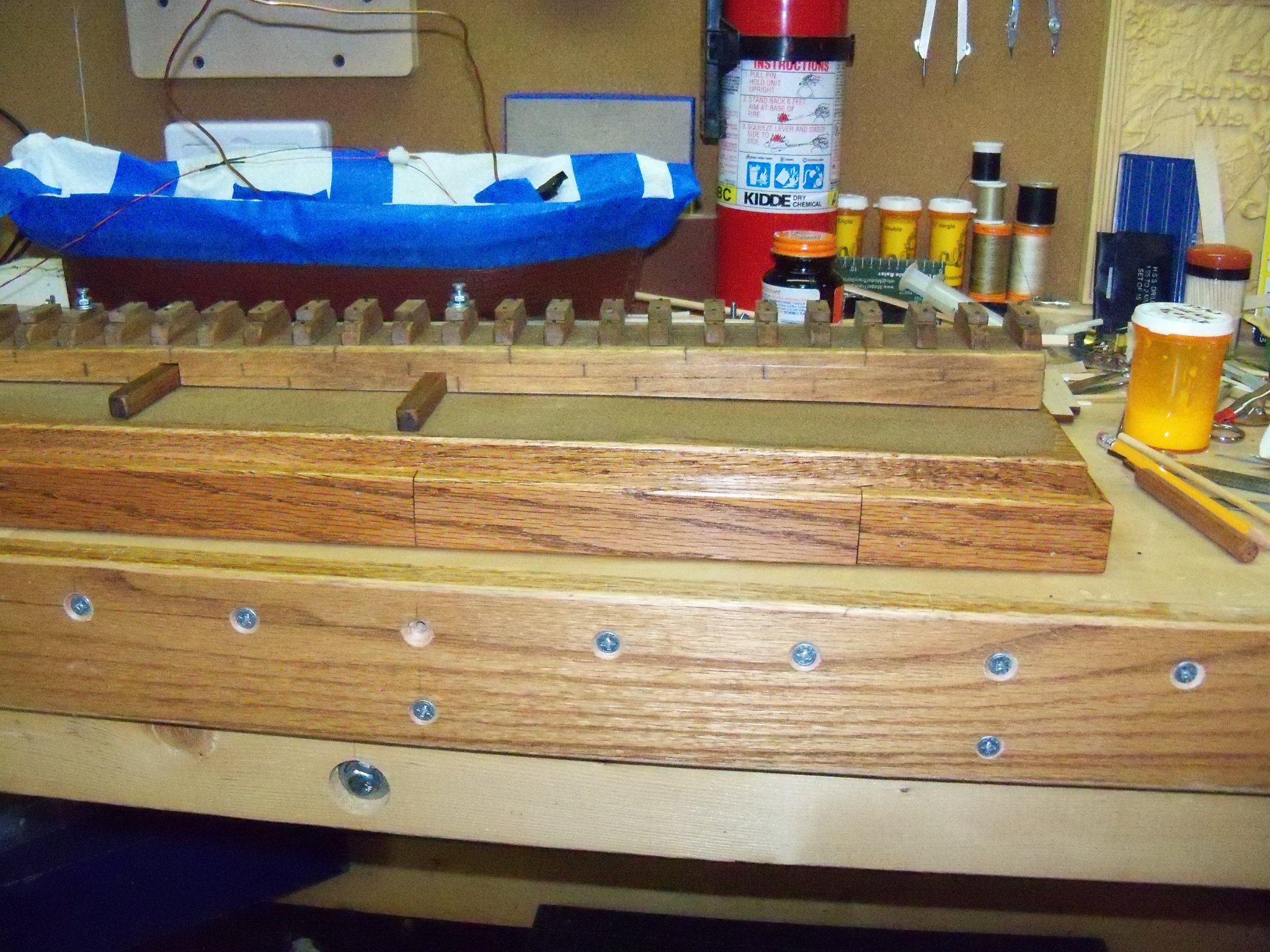
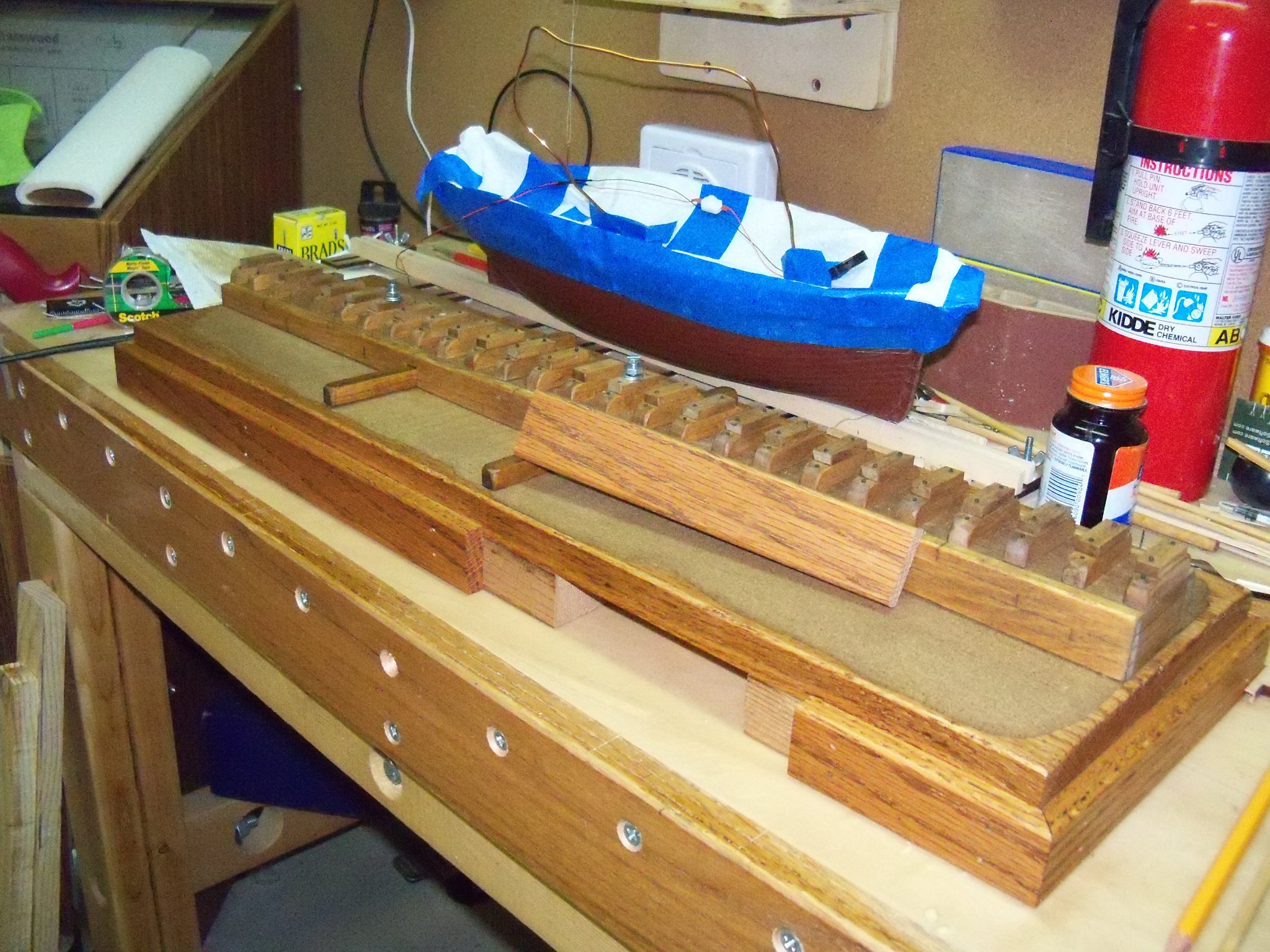
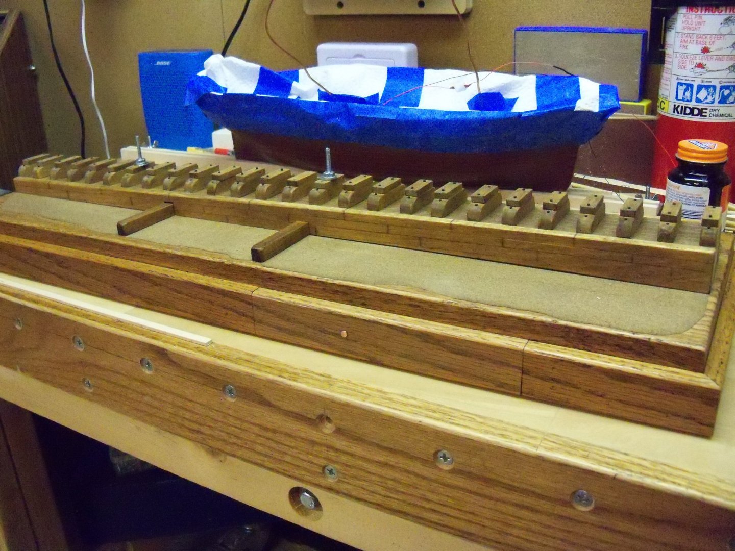
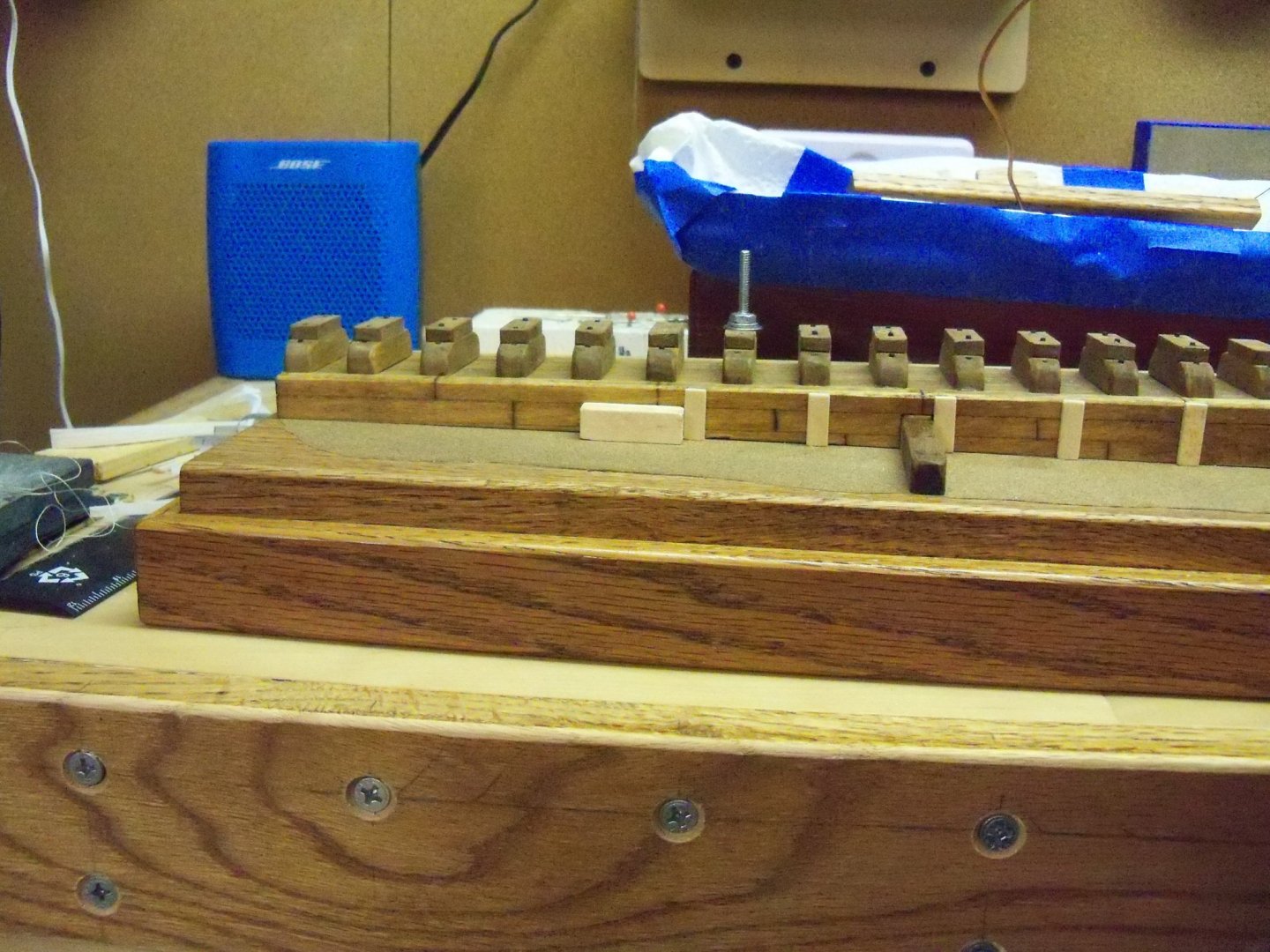
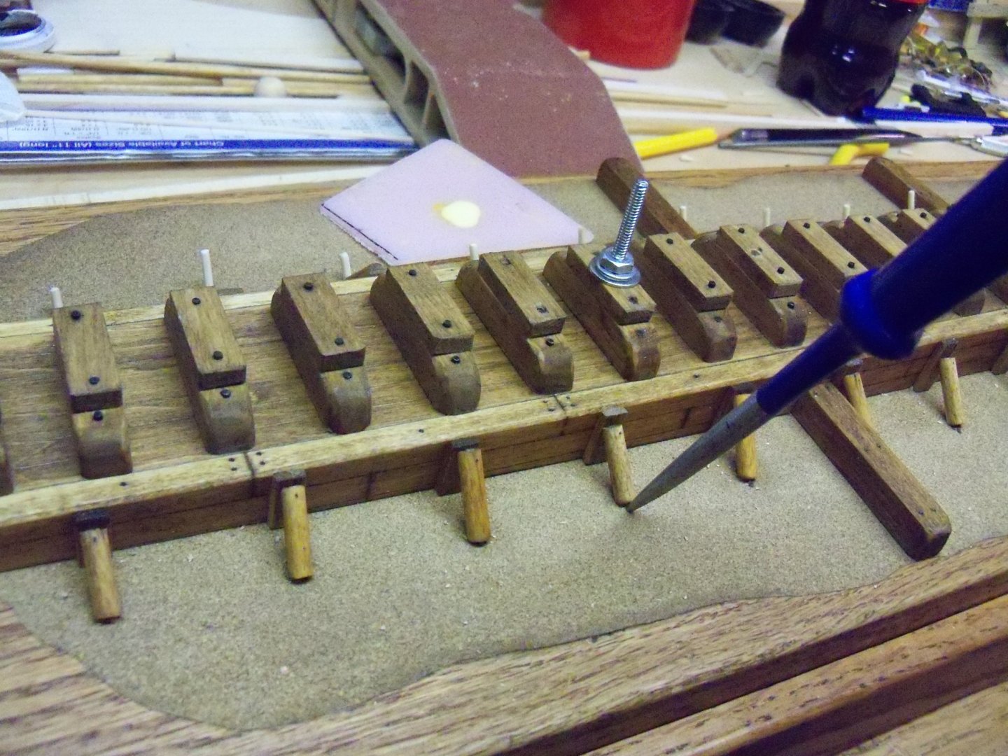
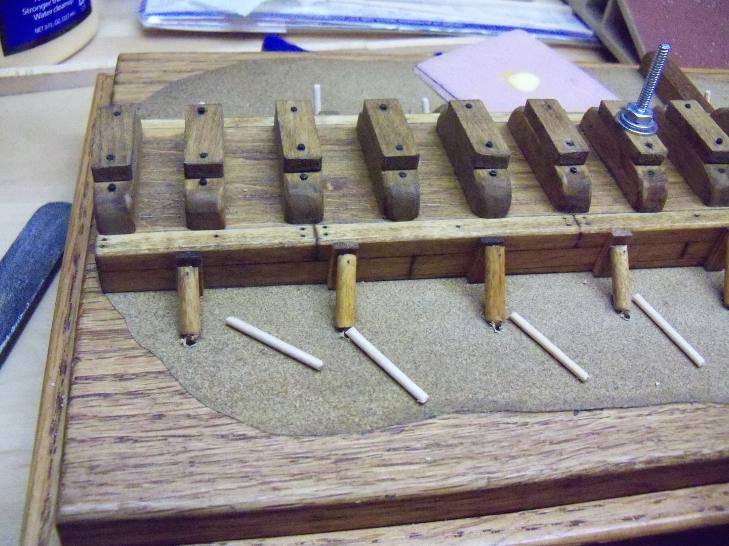
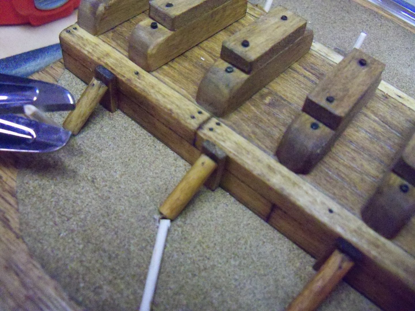
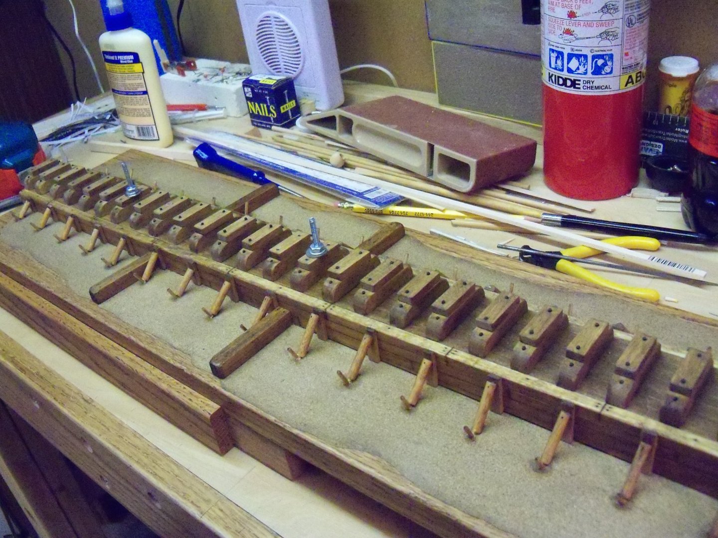
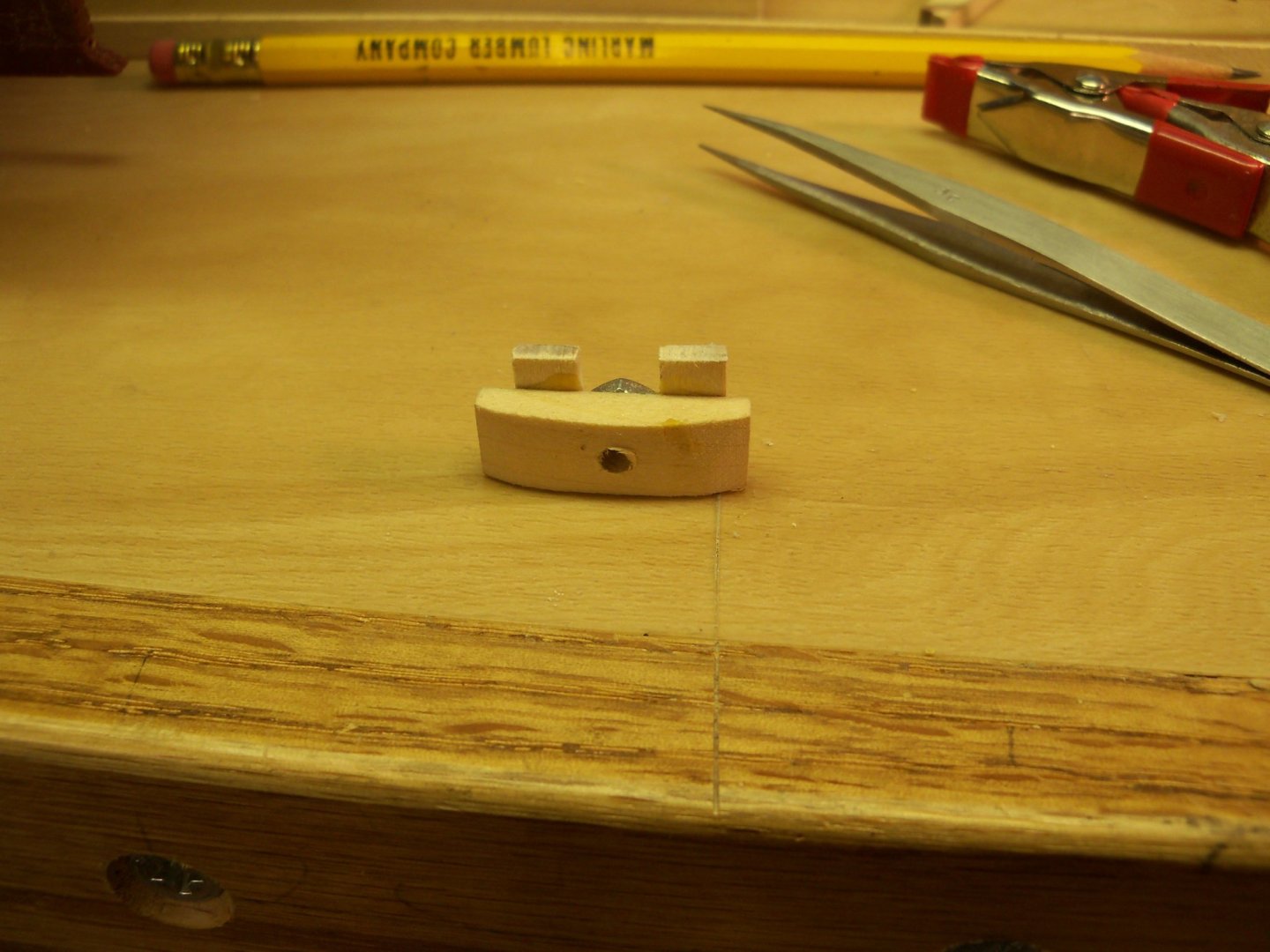
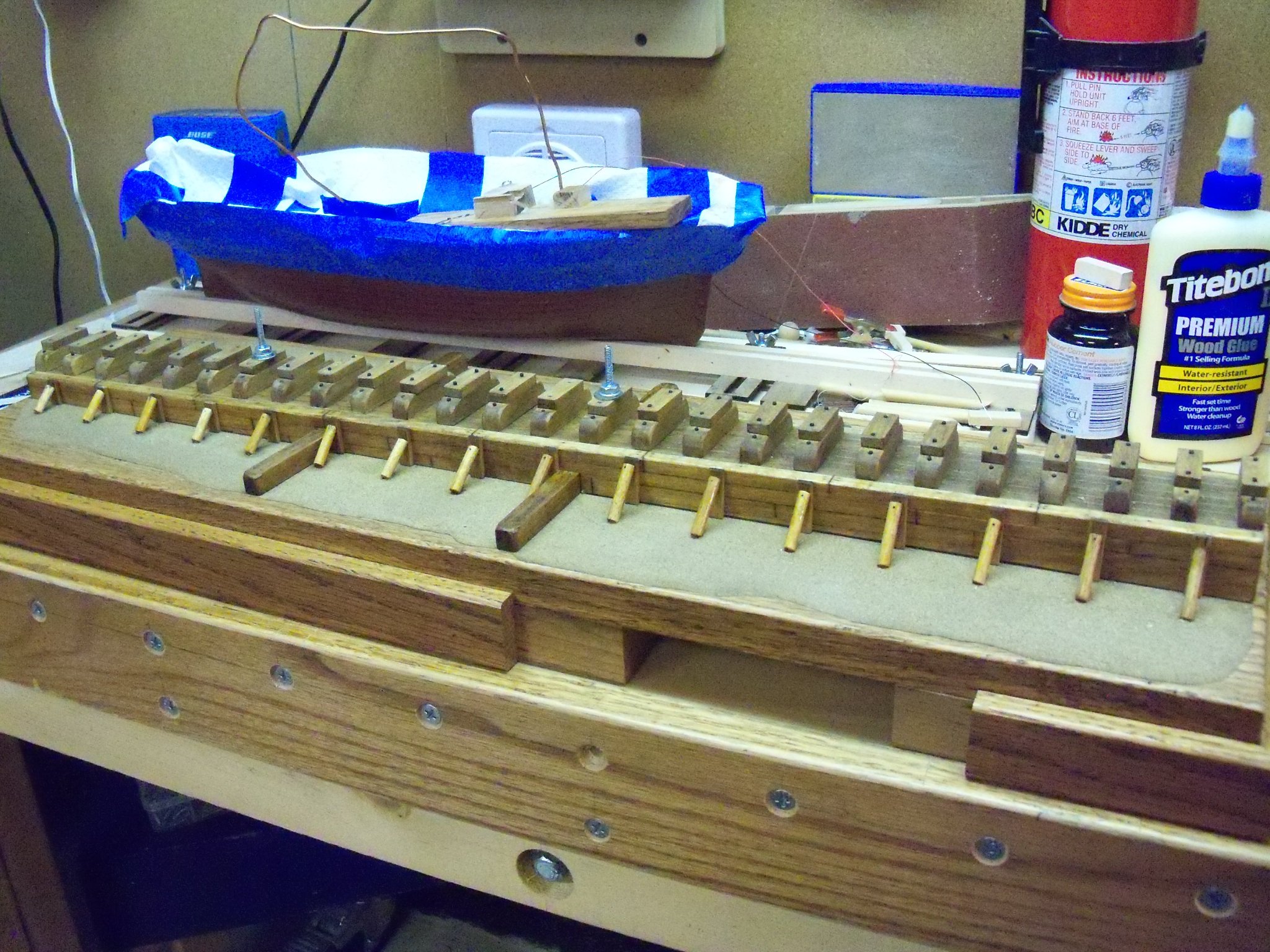
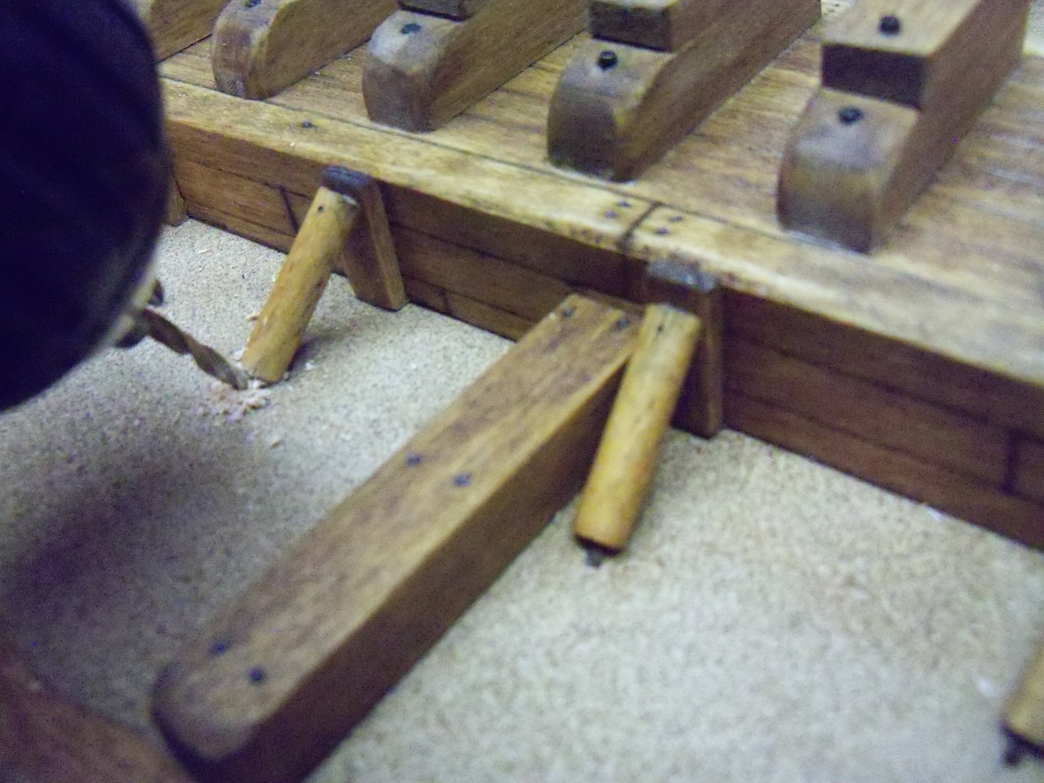
Surprisingly enough, the elevator tech showed up on the 9th as promised. After about an hour of testing and adjusting the limit switches, it was ready to go again!!! So now I was finally able to get a few things taken care of. The launching way ramp was glued into place on the display base with the anchoring bolts tightened down to help clamp it in place. Now the braces for the ways were begun by gluing the 3/32” x 1/4” basswood vertical braces up against the timber walls with carpenters glue. (The concept was shown on a June 7, 2019 posting.) Each one needed to be a different length, so it was all “cut to fit”, no mass production here. I just held each brace momentarily in place for the glue to get tacky before setting the following one. To keep the spacing more consistent, I cut this spacing block to go between. Once all 32 vertical braces were installed, I gave them a good coating of Minwax light oak finish with a small brush. Now it was time to make the diagonal braces that were made with short pieces of 3/16” birch dowel. Unfortunately, each one of them was also a different length so more “cut to fit” was involved. These were set at an angle of roughly 45 degrees. The bottom ends were set with carpenters glue into shallow depressions drilled in the base and the top ends were also glued and partially beveled to sit flat against the vertical braces. On the top of each brace, a small depression was made with a very sharp F drafting pencil lead to represent a metal spike to secure them. (Similar to my method of showing trennels made in the decking on my June 28, 2018 log entry.) Once all these diagonal braces were installed they were also stained in place. Here are the ways shown below at this point. The bottom ends of all the diagonal braces were held in place with wooden pegs driven into the ground at an angle of roughly 45 degrees. To make the pegs I clipped the pointed ends off of some round wood tooth picks and used the remaining center portion. (The pointed ends will be used later as trennels to hold down the false deck.) One end was sanded smooth for the exposed end of the peg. Using a steel center punch, I located the hole for the peg right up against the bottom of the diagonal braces and gave it a sharp rap with my hand as shown here. Once all of the impressions for locating the pegs were made I came back with a drill bit matching the diameter of the tooth picks and drilled about a ½ “ deep hole at a 45 degree angle. I laid out the pegs at the holes with the sanded ends set near the holes to speed things up a bit and keep me from putting the wrong end in the hole. Now, production style, I installed the pegs one by one. I bottomed out the sanded end of the peg in the hole, clipped it to length, removed the peg, dipped the clipped end in carpenters glue, and pushed that end of the peg back into the hole using a D sized battery. (Using the flat end of the battery gave me more control and caused less damage to the sanded ends of the pegs than using a hammer.) I repeated this operation for all 32 pegs. Once the pegs were installed they were all stained in place. So, the launching ways as shown below are complete except for the main hull braces which won’t be installed until the hull is in mounted on the stand. There are some more details to add yet, but they can wait until later.


-
I think the center of the line would be the way to go. I use a pair of drafting dividers with a center wheel so it won't loose the setting.
-
Along this line of thought, I came across my pencil sketch of the Monitor and Merrimac battle in Hampton Rhodes in the civil war. It was taken from a term paper that I wrote back in High School. (Just a few years ago)
.thumb.JPG.5f3d92c02fac6acdf25f30bbce5fa505.JPG)
-
After I left seven messages for the elevator service manager to get some service and finally an impatient call by the admiral to the head office on the 26th, I finally recieved a reply that same day. The manager said they needed to have a company meeting the next day to rearrange their scheduals due to the elevator service tech just returning from quarantine. On the 28th I called again, but they had no decision yet. This morning I was finally informed that they would come on the 9th. Like I said previously, I won't be holding my breath.
-
Speaking of emotional war movies, I just saw American Sniper, a Clint Eastwood film staring Bradley Cooper. Clint has starred in or directed quite a few other good war movies like Heartbreak Ridge, Flags Of Our Fathers, and Letters From Iwo Jima in which he explores the combat of course, but also the effects on the participants themselves. But if you need a good laugh there is also Every Which Way But Loose and its followup Any Which Way You Can where he plays second banana to an Olymia beer-guzzling orangatan named Clyde.
-
Sometimes it seems that there are times when everything that can go wrong does just that. With Covid-19 we started this year off with a bang, and that just keeps on going way beyond the miracle endings proclaimed by the one least qualified to know. Things just seemed to accelerate from there. They really started to go more awry last month when our clothes dryer was out of commission for a week or so. Then I went in for a little MOHS surgery with a little extra trauma for my toe just thrown in for giggles. I no sooner pretty much recovered from that, when I had to go in for Colonoscopy surgery yesterday. Now today I found out that the elevator to our basement has also just decided to go on the fritz! Luckily the admiral was here when I got in the elevator. Because, the door to the cab wouldn’t open to let me back get out. She had to use the emergency exterior key to the door to let me out. Luckily it was at the top when it happened, so we didn’t have to find some other way for me and the wheelchair to get back upstairs! I just got off the phone with the new service manager (the third one since we had it installed in Dec. 2018) to try and schedule a service call. They can’t have anyone here till later next week and that comes to the tune of $375 🤑 for the call plus labor and any parts needed. Hopefully it can be fixed quickly, easily. (And cheaply?) Someday, I may be able to get back down to the basement model shop. However, at this point I’m not going to hold my breath after the way over extended time for the original installation of the elevator. Only time will tell I guess.
-
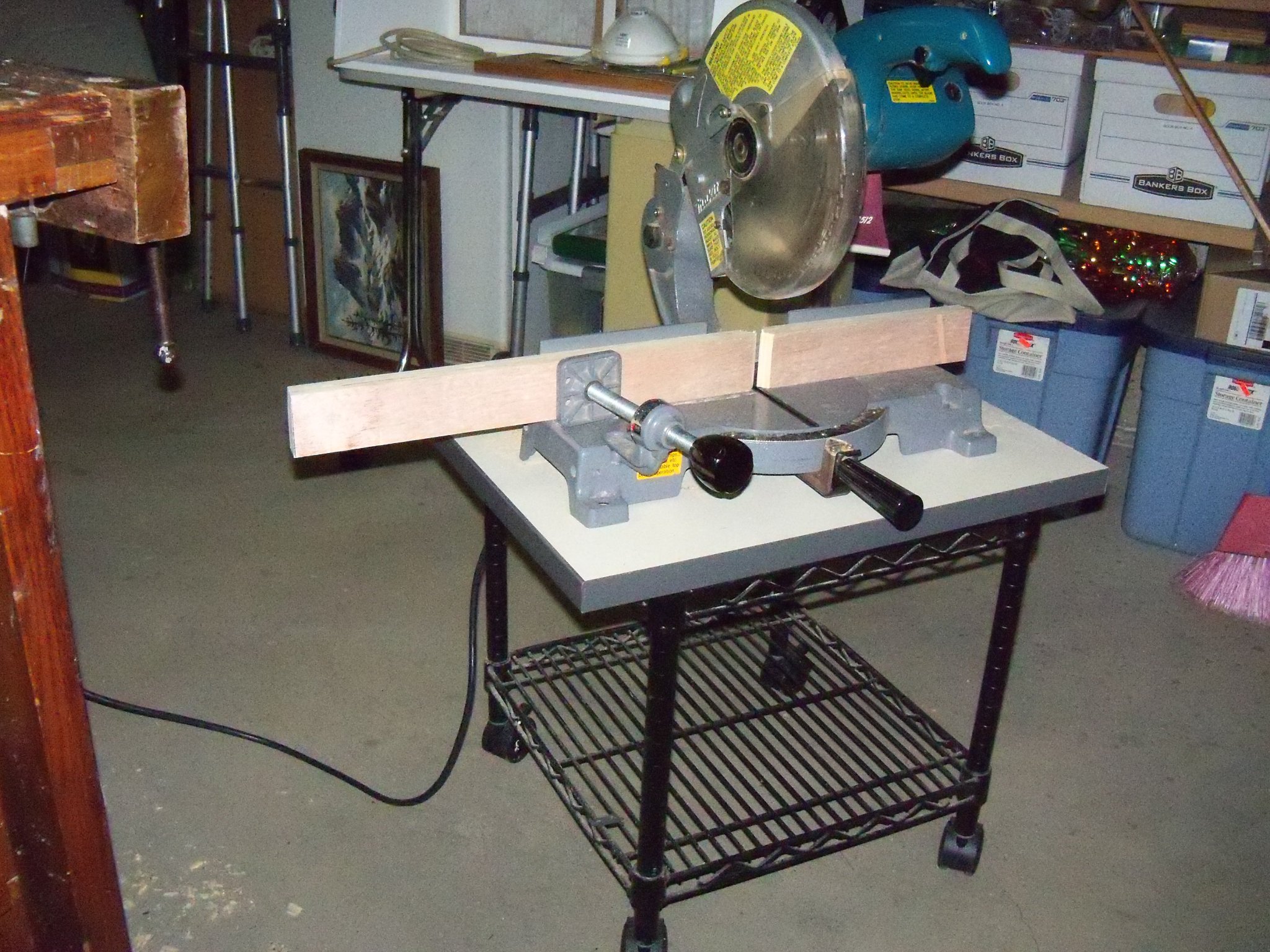
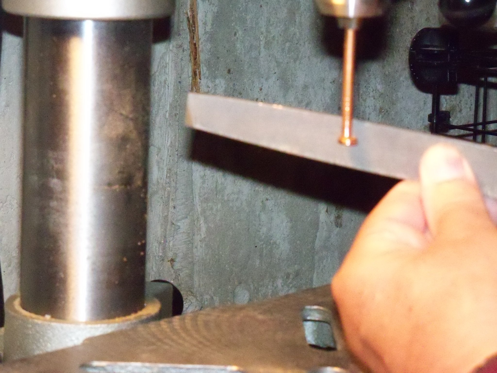
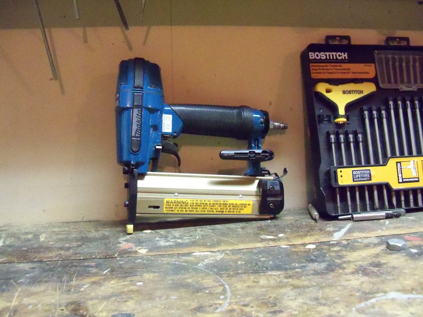
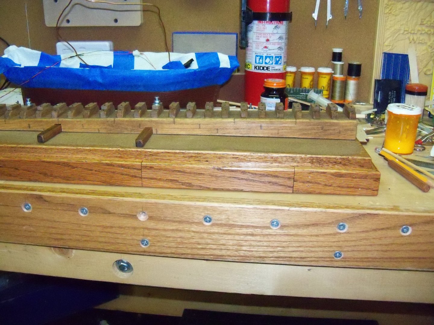
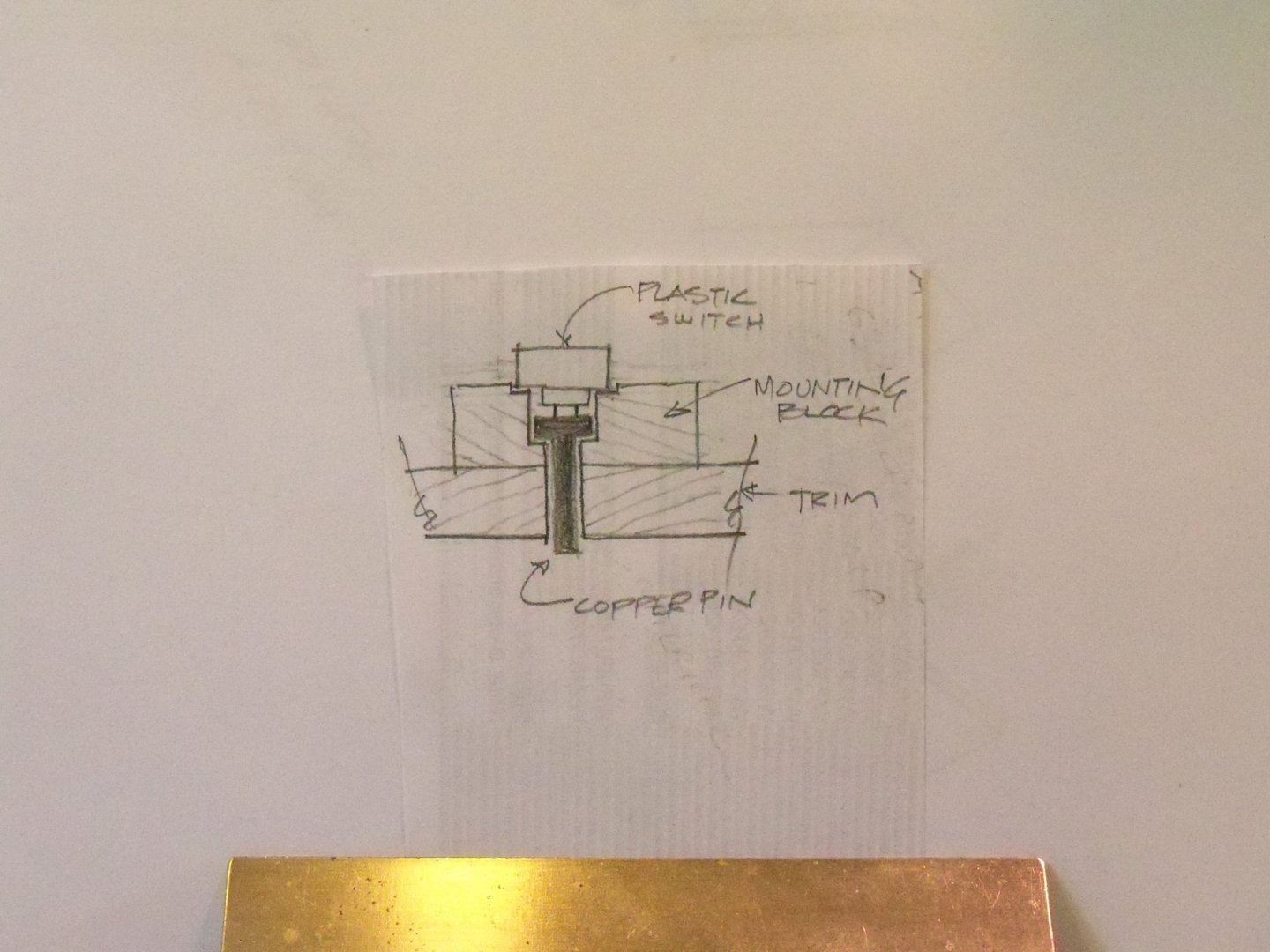
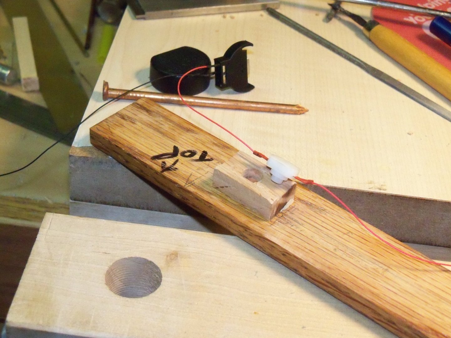
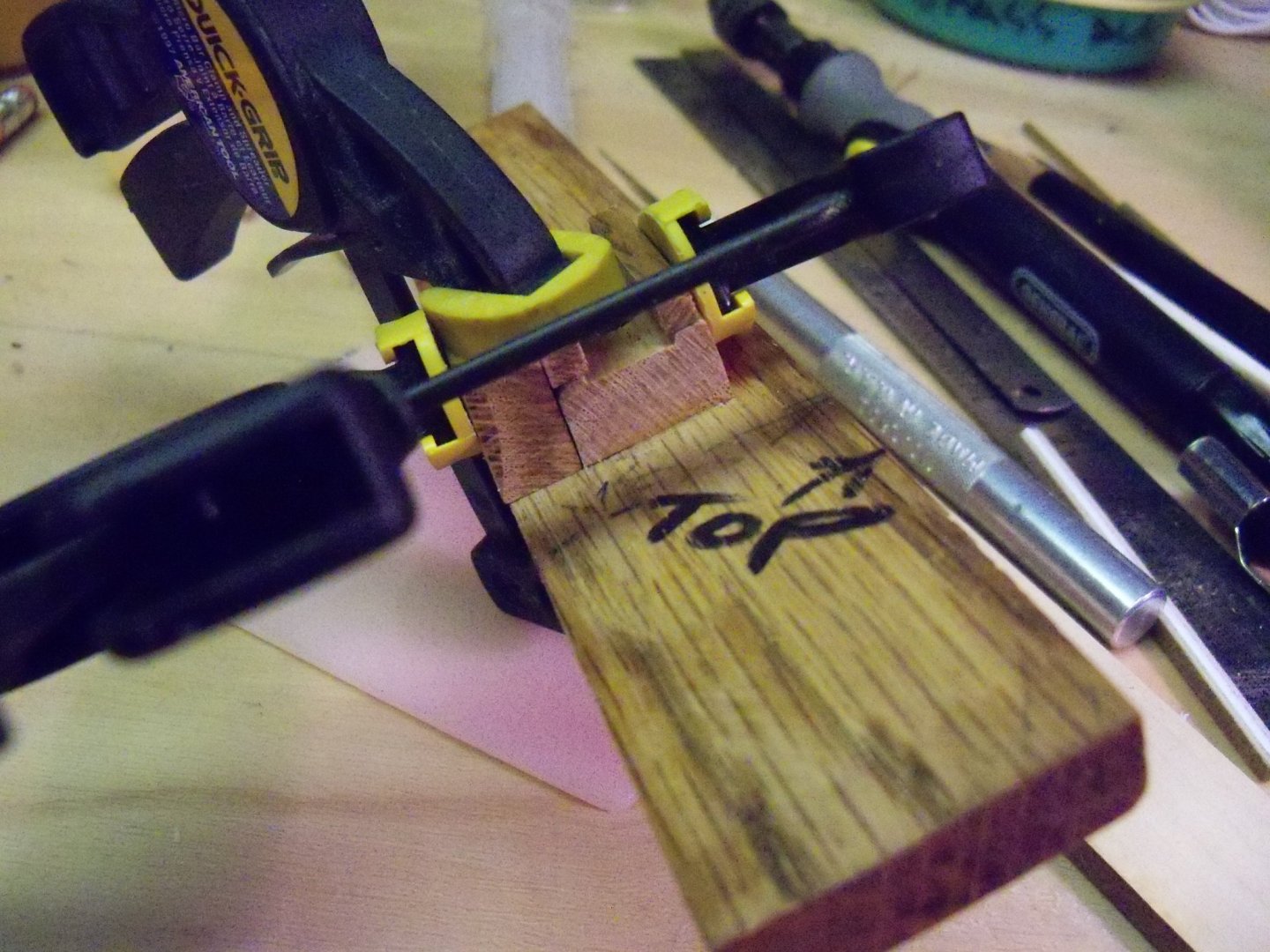
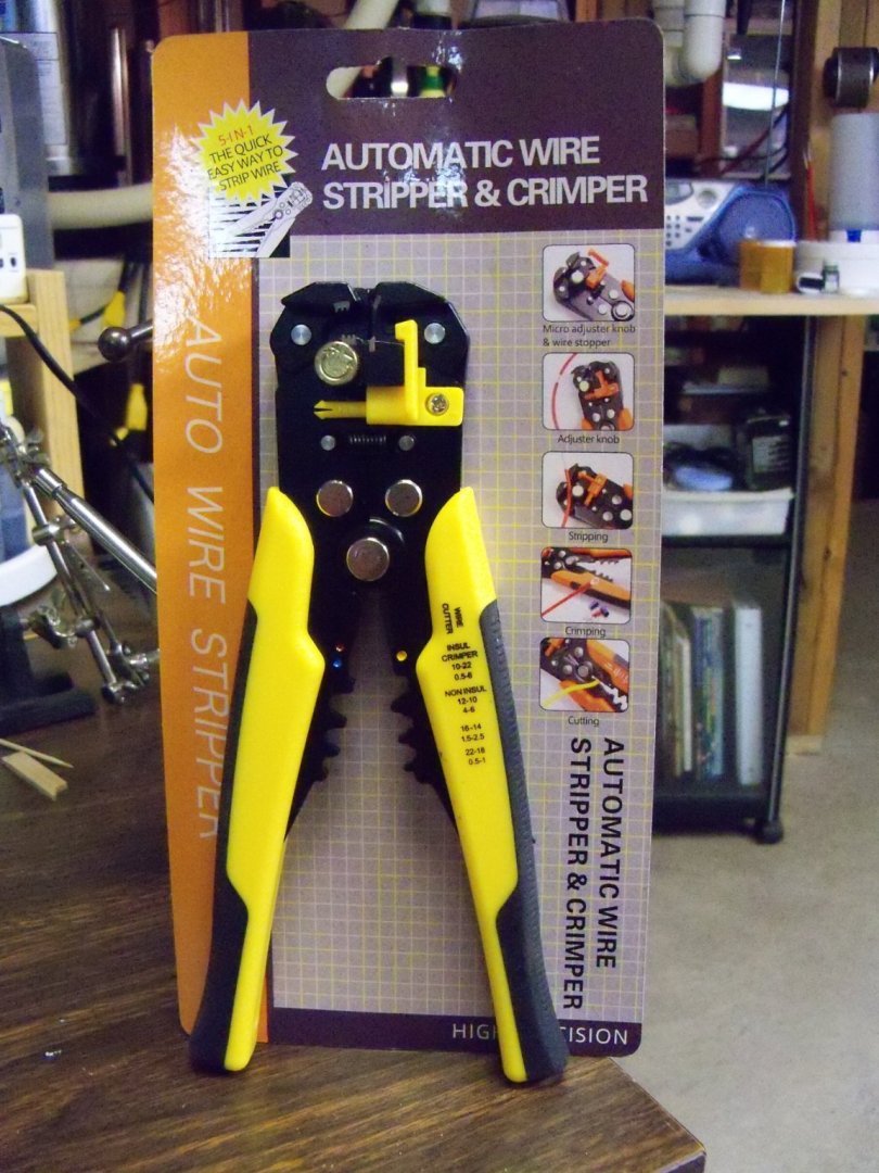
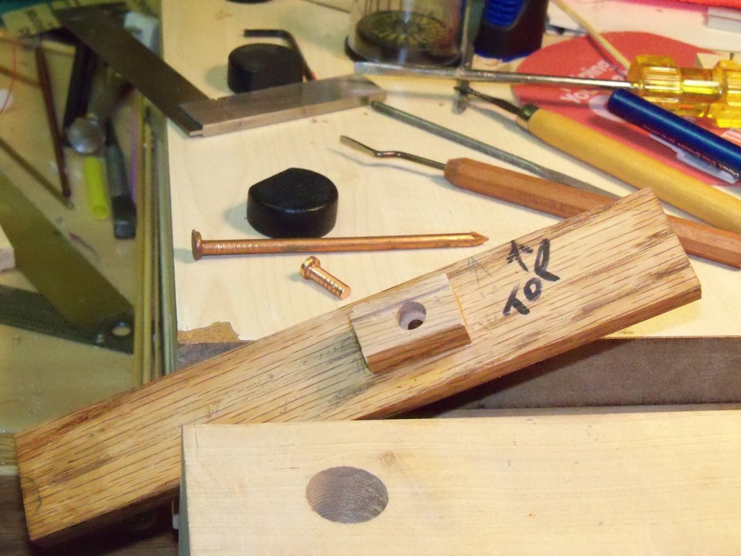
Despite my best efforts to blend that plug into the base, the wood grain didn’t match very well and as a result it was still somewhat noticeable. So I simply redrilled the holes for the mounting bolts to allow the unplugged side of the base to now become the front. Once the base was redrilled, I pieced together three sheets of 150 grit sandpaper to represent the surface of the ground around the launching ways. The joints in the sheets were placed to align with the extended timbers that will brace the hull. Once the edges of the paper were trimmed off, I held them down on the base and traced the outline on the baseboard. Since the board was already prefinished, that finish was sanded off the surface up to the traced outline of the paper to allow the carpenters wood glue to bond. A 50/50 water to glue mix was spread out with the edge of an old credit card up to the traced outline. One unforeseen complication that developed was the fact that the paper soaked up the glue much faster than anticipated and the edges of the paper quickly curled up. So it was a bit of a scramble to flatten and hold it down to dry. The launching ways, various boards, clamps and weights were assembled and applied as shown here. The base was left to dry overnight and the next day the surface was given a light coating of Minwax honey oak just dabbed on here and there with a paper towel and given a quick brushing to even out the coloration with a wide stiff bristle brush. Then all of the excess was soaked up with paper towels and set aside for a couple days to dry again. Now it was time to work on the trim molding. Using my Makita chop saw shown here, the back side and the two end pieces were cut to length. The saw doesn’t slide, do compound cuts or have a laser guide, but then I bought it way back in the 90’s so I just had to “rough it”. (One trick that my grandfather taught me when cutting miters, was to stain the cut ends before assembly, making the joint less visible even if your cut wasn’t as precise as you wanted it to be.) Once these three trim pieces were cut, they were nailed in place with my pneumatic Makita brad nailer show here that even predates my chop saw. However, it still works much beter for me with my diminishing manual skills at trying to use trim nails and a hammer. Now that the easy parts of the trim were done it was time to work on the more involved job of making the front piece. The trim at the front needed to have a central portion removable to mount the switch and to allow replacing the battery when needed without turning the whole case upside down. In order to make it appear to be more like one continuous piece of molding, it was composed of three separate pieces cut from the same length of trim so the grain pattern would appear to continue somewhat uninterrupted as show here. Unfortunately, my chop saw uses a 1/8” thick blade, so the overall piece needed to be about 3/8” overlong with a miter cut on each end. The location of the removable central piece was determined, allowing the joints to overlap the blocks. Then with two 90 degree cuts it was separated from the end portions. Those two mitered end pieces were now nailed to the base. Next, to make the central portion fill the gap, I crept up on its length with my disc sander until it was a fairly tight fit. Here is a view of the unassembled front trim before the final fitting. Now that all of the trim was cut and fit to my satisfaction it was time to work on the mounting of the light switch and battery fittings. The first step was to make a mounting block for the switch; I sketched up this diagram of how the switch would function. Since the switch function was actually a push button, I needed an extension plunger to go through the face of the molding. Being a notorious scavenger with limited metal working tools or skill, I went through my misc. metal bins and came up with some 16d solid copper nails. I shortened one nail to about two inches long with a hacksaw and chucked the shaft of the nail in my “metal lathe.” (alias drill press) With the drill press on, the nail was machined into shape with a coarse metal file. Being just a common nail, the head was not really centered on the shaft with anything approaching accuracy so it was ground down until it was even and the diameter was just slightly smaller than the step on the face of the switch. The shaft was also filed down until it was looking more like a polished custom fitting. Here you can see both the full size copper nail and the finished copper extension plunger in the background of this photo. Using a small scrap of the molding for the block, I glued and clamped it to the back side of the trim located to fit in the open space between two of the base board spacing blocks. Once the glue set, I selected a spurred wood bit sized to match the step on the switch and drilled into the back of the block until it was just short of the molding. Then, switching to a drill bit matching the shaft of the plunger, I drilled all the way through the block and trim. Here is the trim at this point. Using wood chisels and files, a groove was routed out the width of the main body of the switch. It was only about 1/16” deep, just enough to hold the switch in place. The switch itself operates with a spring mounted plunger, that when in the off position is fully extended. Once the plunger is depressed it clicks and stays depressed just proud of the step on the face of the switch housing and is in the on position. (You can see in this photo of the switch that shows both the plunger and that step on the face of the switch.) After much checking and fine tuning, the depth of the bore for the head of the plunger was adjusted. While holding the switch and plunger in place, the actual operation of the switch was checked while hooked up to the battery and lights. The copper plungers’ projection beyond the face of the molding while the switch was in the on position (fully depressed) was noted and marked on the end of the plunger. Adding about 1/16” to this mark, the plunger was removed and cut off at this length. The cut was filed smooth to a polished finish and sprayed with Tamiya TS-80 clear matt acrylic varnish. Here is the molding in place showing the copper plunger installed. At this point the switch still needed to be fixed in place so that when the plunger is depressed it doesn’t push the switch housing out of place. I ripped down two narrow strips of oak to flush out with the backside of the switch housing and glued them in place on both sides of the switch with wood glue. In the unlikely event that the switch needs to be replaced at some point, I glued and clamped another small block of wood alongside the switch block. A thin piece of plastic was cut and screwed to that extra block with a single screw to allow it to swing over the back of the switch and hold it down and yet still be able to swing away allowing the switch to be removed. So here is the completed switch housing below. As far as the battery housing is concerned, it will just be taped to the backside of the removable trim piece to hold it in place and yet be easily released for changing the battery. I had to splice some additional lengths of wiring to reach the new location of the switch. The splices were done with the help of this recently purchased new tool that could strip the insulation off of the very thin wire that came with the lighting system without damaging the copper. The ends of both wires were bent back and hooked together with the wires tightly twisted to form a very secure mechanical splice. Additionally, the wire splice was soldered and covered with shrink tubing heated with an old blow dryer. All of the remaining loose wire will just be taped to the bottom of the base board with sufficient slack to allow removing the switch trim piece to get at the battery. An additional length of shrink tubing will be applied to the wires as they are run through the base board, launching ways and the keel of the ship for a little bit more protection. I think that a couple pieces of double faced tape will be sufficient to hold the switch trim piece in place on the base. If not, I could always recess pairs of thin magnets to do the job.


-
Well Jaager, I checked with the website and according to them it doesn't adhear well to plastic. Thanks for the suggestion anyway.
-
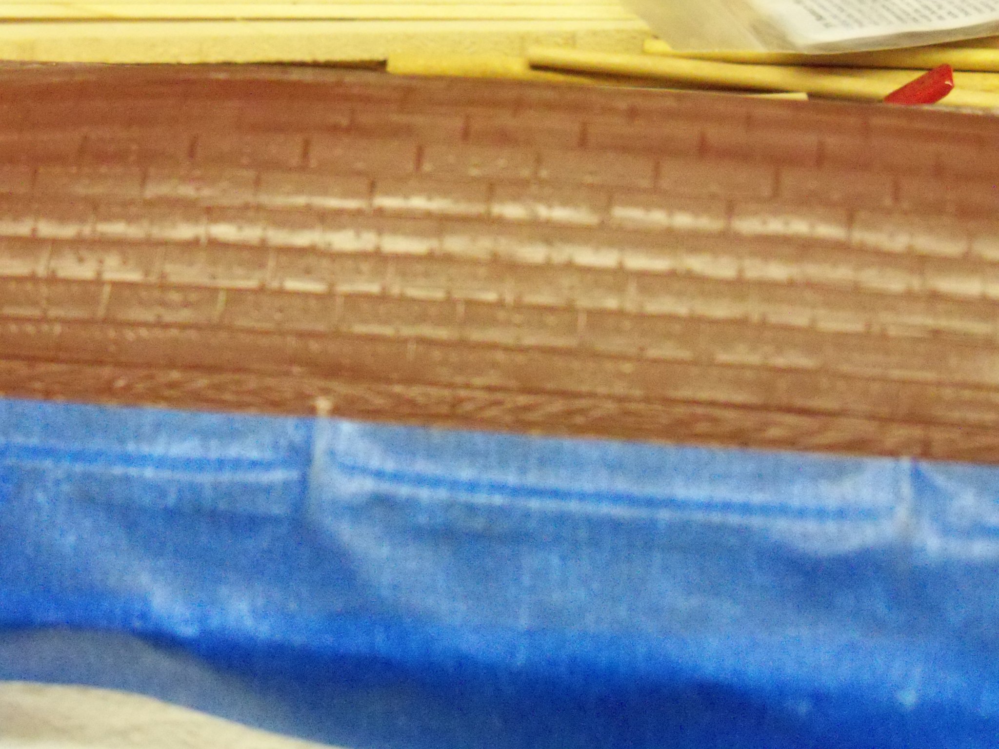
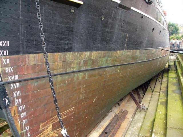
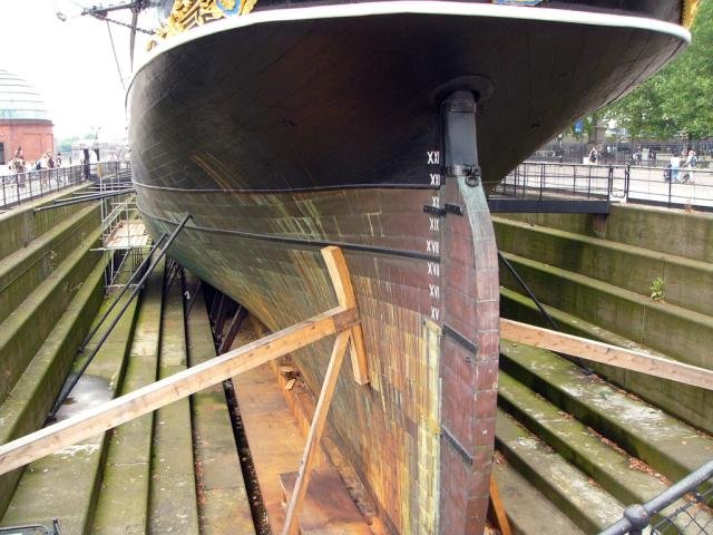
Actually, my intent is to show the ship in dry dock for refitting rather than as a museum ship. The copper bottom would now be exposed for some time to the air after having returned from a long whaling voyage, thus the green and white mix to the color. As far as the vertical streak pattern goes, I am looking at these two photos below of the Cutty Sark that does show them.
-
Shades of the B&W film Fail Safe with Henry Fonda and Larry Hagman (of J.R. on Dallas fame).
-
I am now at the point of painting the plastic hull of my Wanderer, and am in a bit of a quandary of how to proceed. I have used a technique promoted by Les Wilkins in his book How To Build Plastic Ship Models in the past with very good results. The technique was to first spray paint the masked hull with Floquil Copper. While this coat of copper paint is still fresh, you take a medium paint brush and apply Floquil Light Green paint with random vertical strokes, always brushing away from the waterline. Then using a clean medium paint brush this process is repeated using Floquil Antique White. Now with a clean brush frequently dipped in turpentine (Not lacquer thinner because it will eat right through the copper paint!) lightly brush with vertical strokes (again away from the waterline) over the green and white paints while they are still wet to make these two colors meld with the copper. Also, don’t brush too hard or you can rub through the copper paint and the turpentine can harm the plastic. The next step is to use a string or wire to suspend the hull in midair to dry for 3 or 4 hours which will allow the turpentine to run down to the keel as it dries. After the turpentine has evaporated and the paints have dried, take a piece of No. 600 sand paper and lightly sand the full length of the hull with back and forth strokes until some of the paint has been rubbed off the edges of the plates to make them somewhat more pronounced. The last step is to take a clean damp rag and wipe off the resulting sanding residue from the hull. The only problem here is that Floquil paint was lacquer based and is no longer available. I am wondering if this technique can be done with the enamel or water based paints that are available now. I have two 3 oz. cans of Testors copper spray enamel to act as the base coat and since Testors paint is still readily available in green and white; could this technique be employed here with their enamel paint or maybe water base paint?
-
I would agree with that assesment also. Another consideration that occurs to me is the fact that wood and metal do not expand or contract at the same rate when reacting to changes in heat or moisture which would more than likely raise hovoc with the edges of the mortices inviting the intrusion of even more moisture.
- 24 replies
-
- 2
-
-
- pivot gun tracks
- pivot gun
- (and 1 more)
-
You need to apply a wood filler like Minwax 21600000 high performance filler first. This particular brand is my favorite as it's ready for sanding in about half an hour. Then sand it down until you get it to your desired smoothness. Once done you can paint it and have the smooth finish you're looking for.
-
2021 CALENDARS ARE GOING FAST!!
BETAQDAVE replied to ferretmary1's topic in NAUTICAL RESEARCH GUILD - News & Information
I'm in. -
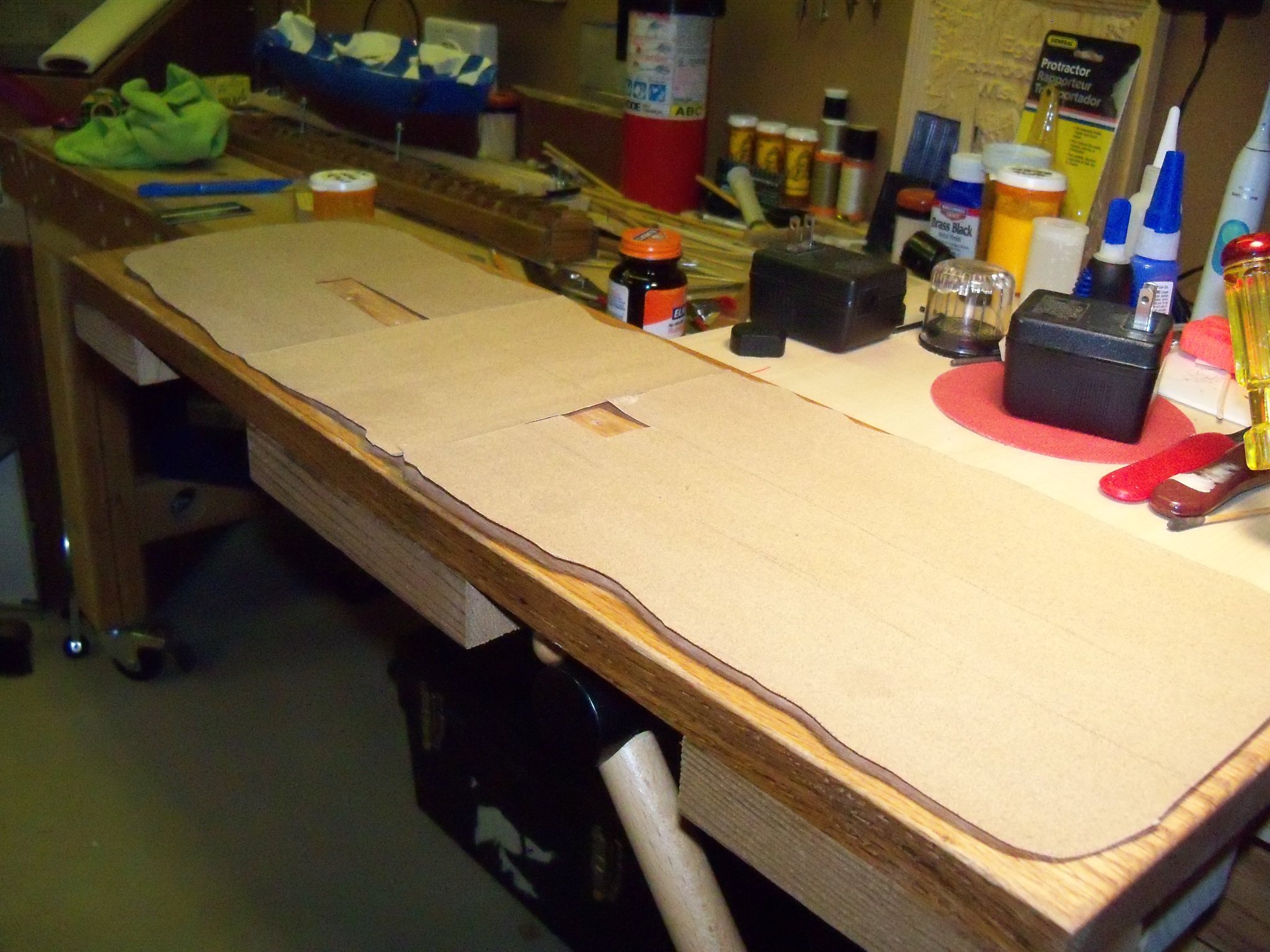
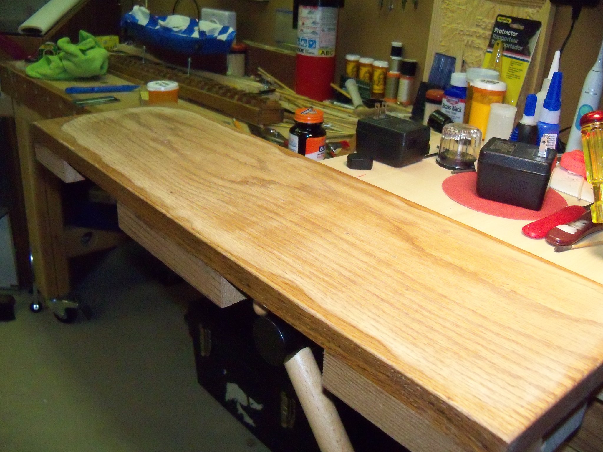
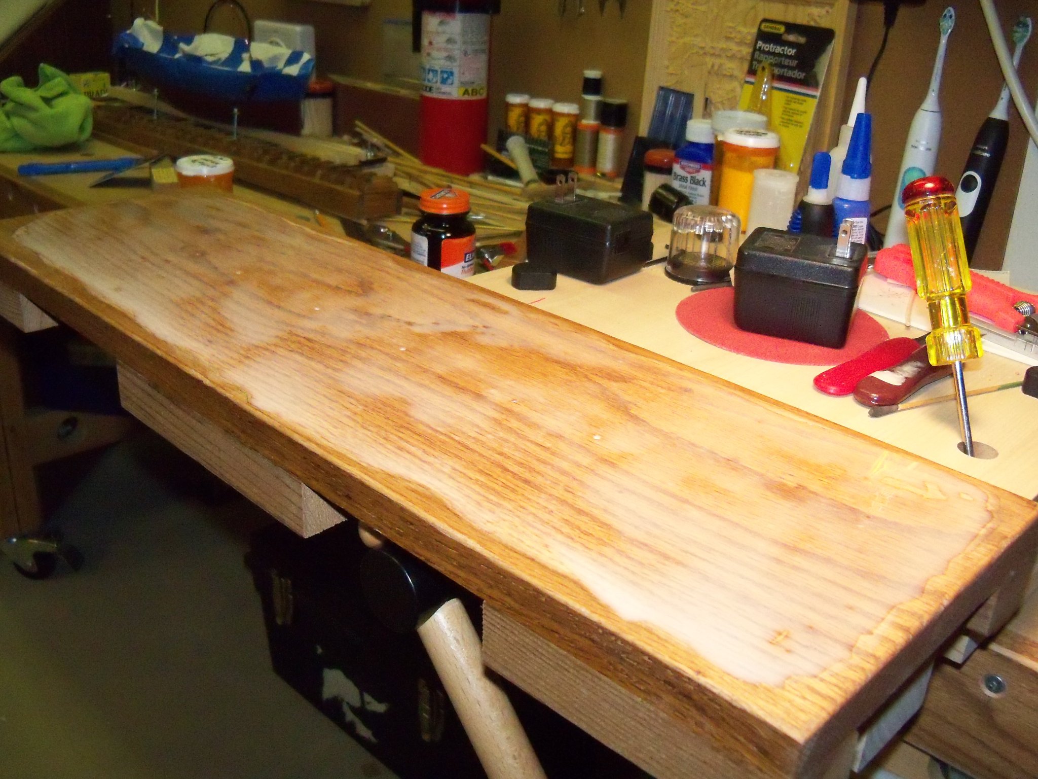
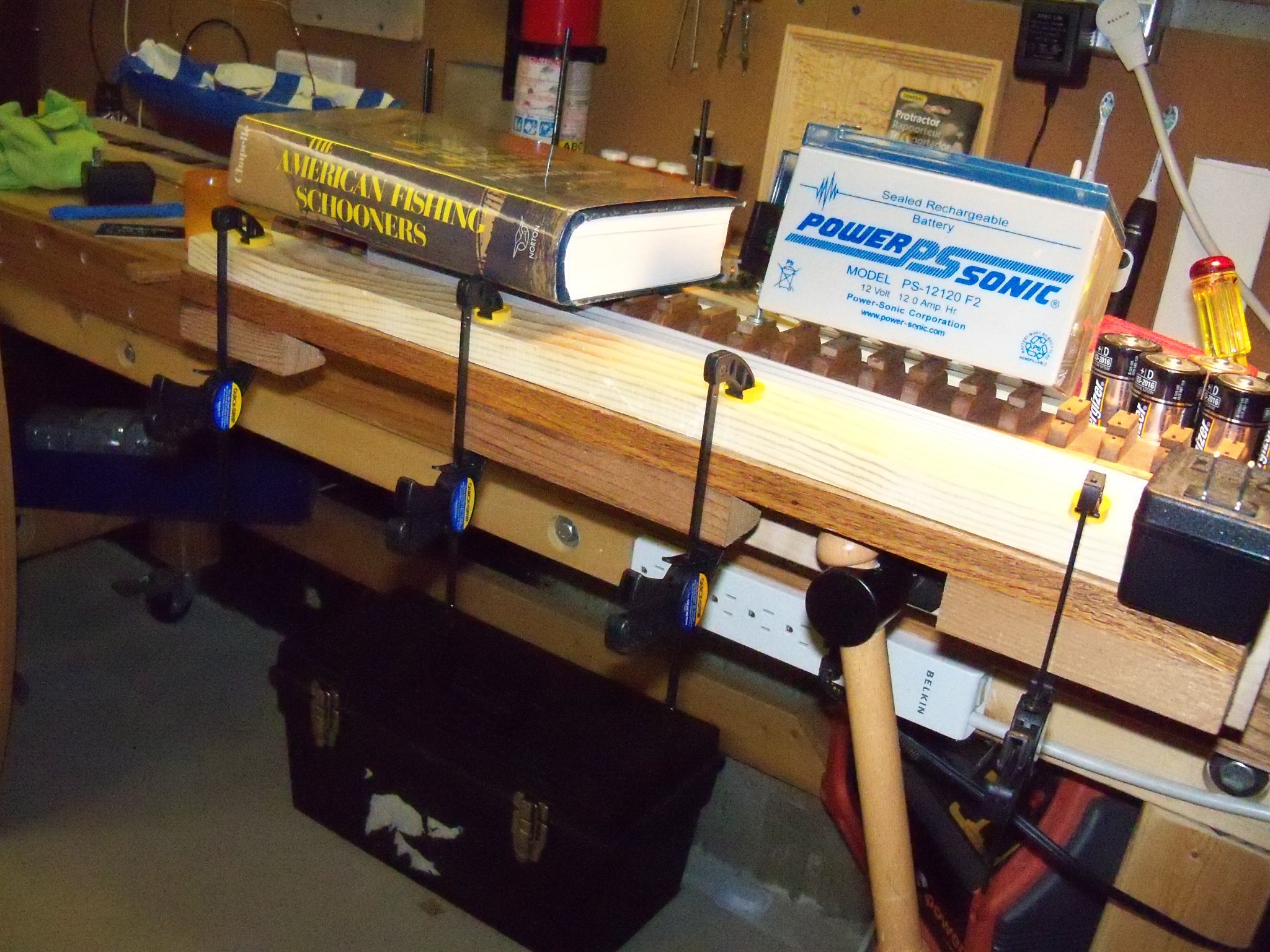
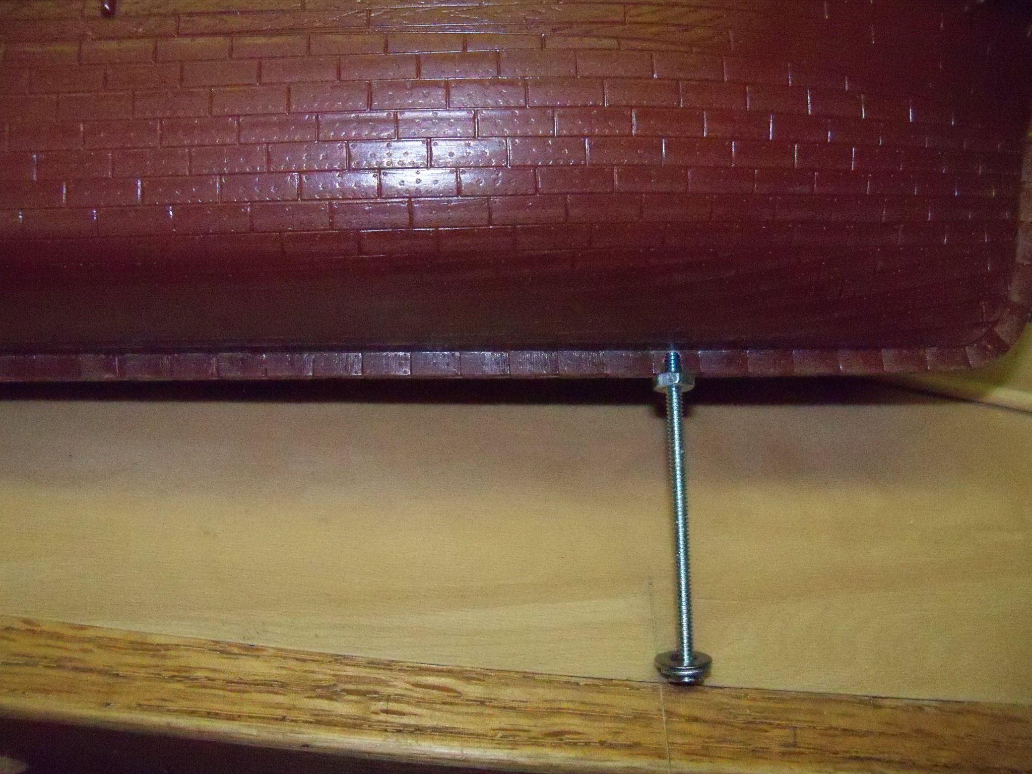
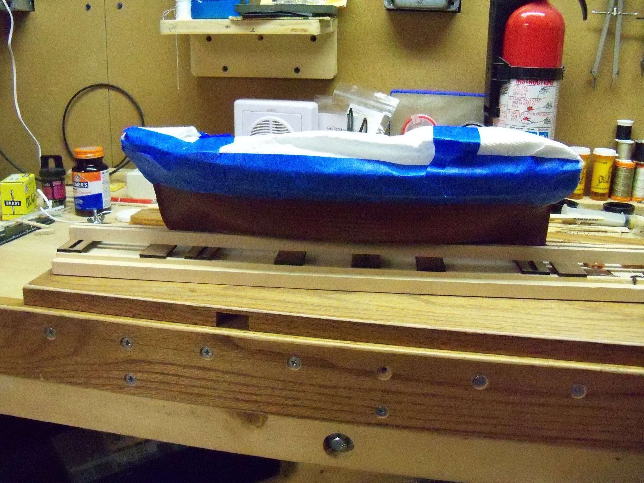
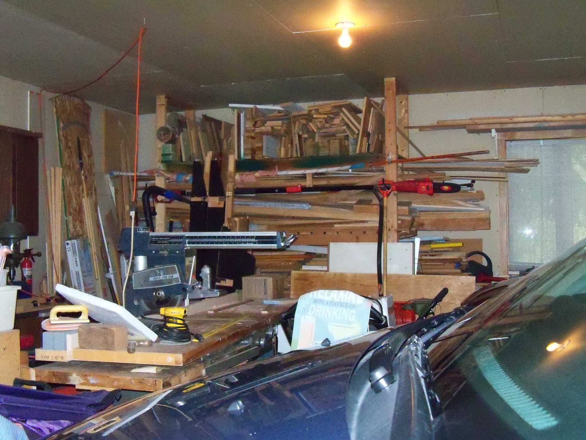
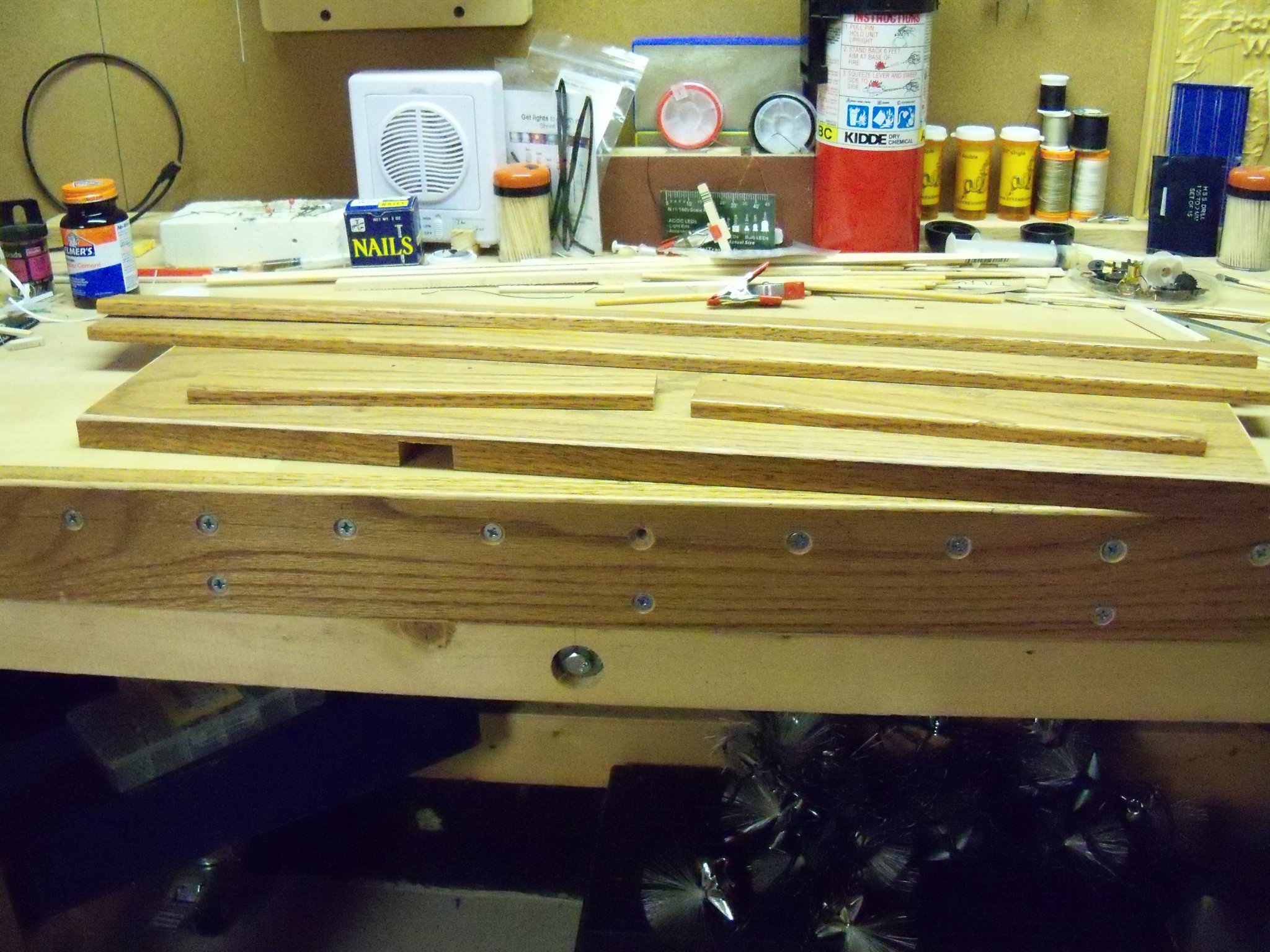
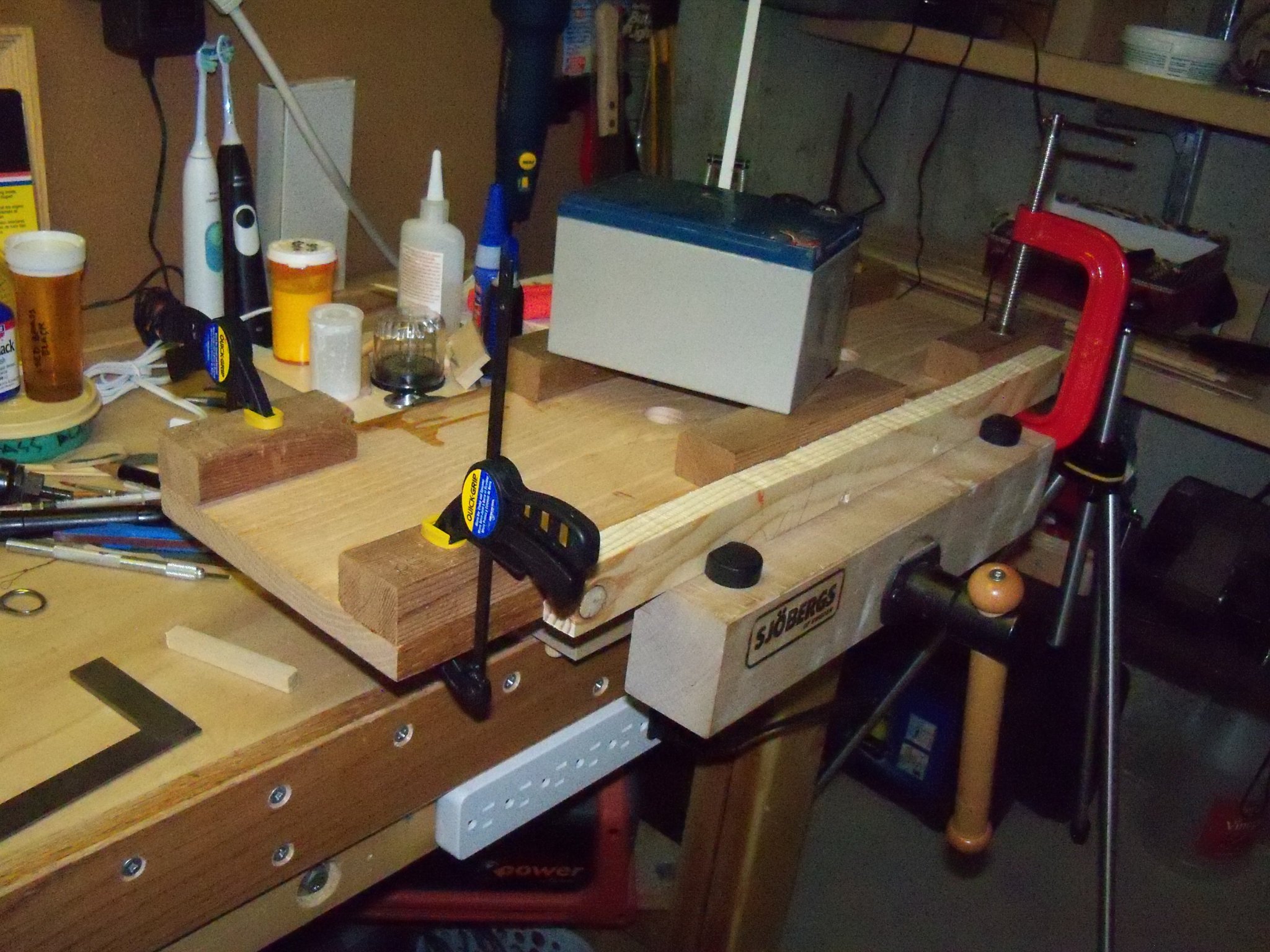
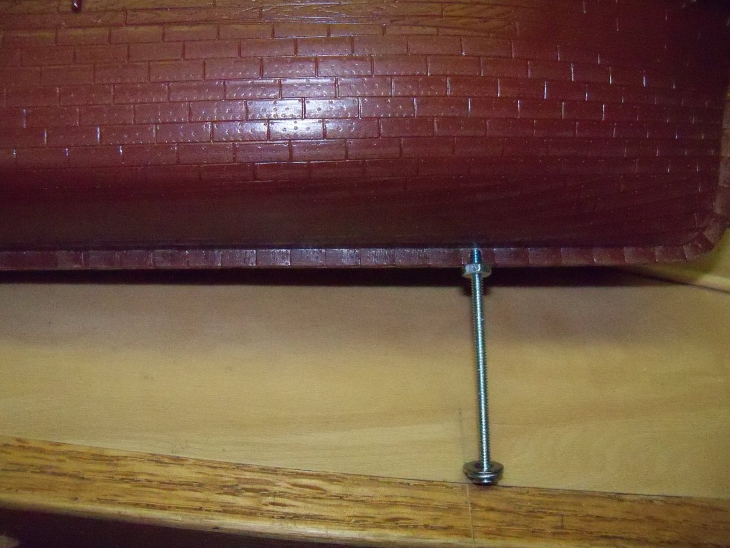
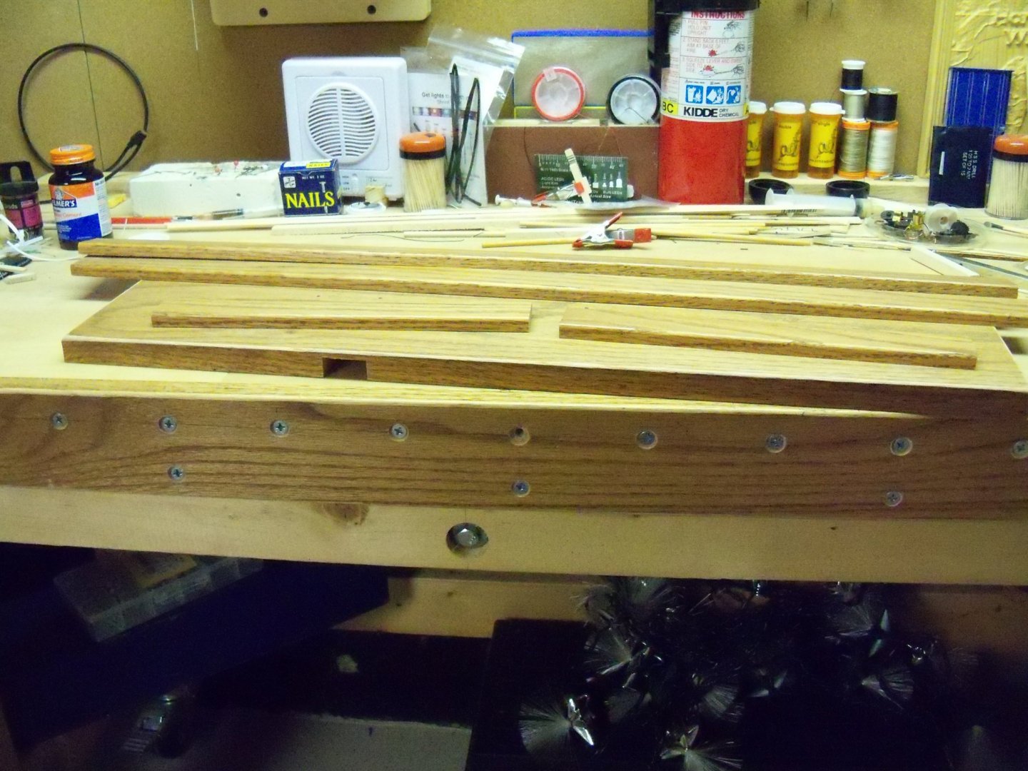
Finally, after a rather extended time away from this build and its log for a long list of reasons including work on my Phantom build log and waiting to remove the bed frame that blocked my access to my saws, I returned to working on this display base. The 1 x 10 oak base board was trimmed to its final length, the top edges were eased (slightly rounded over) and then lightly sanded. I positioned the launching ways on the base board and using a 7/64” drill bit through the predrilled mounting holes, I gave it a light tap to mark the locations of these holes on the base board. Since I had finally determined that I needed to use 1/8” bolts now for mounting the ship, all of the predrilled holes needed to be enlarged. I started by carefully enlarging the holes in the ships’ hull with a 1/8” drill bit mounted in my battery powered screwdriver/drill once again to avoid overdoing it. Once the holes in the hull were enlarged, I used my drill press to enlarge the holes in the launching way blocks. I drilled all of the 1/8” holes through the base board, and to reduce the length of the mounting screws, I used a Forstner bit to counter bore the holes about 1/2” deep on the bottom side. With the radial arm saw, a recess for the battery and switch was cut through the front edge and into the bottom. Then I used chisels to finish carving out the bottom of the recess. This was the bottom of the base board at this point. Then, just to be sure everything was properly aligned, I test fit the entire assembly to avoid the dreaded “Maybe I should have done things differently” syndrome later. (Its happened before!!) Now I made some hardwood blocks to glue inside the hull to mount some captured nuts for the bolts to screw into when the ship is finally mounted. The block for the stern bolt was the easiest since the inside of the hull was nearly flat there. The block for the bow end however, had to be shaped on the bottom side to match the curve of the inside of the hull at that point. The holes in the blocks were drilled one bit size larger than the bolts since their function is just to act as wooden washers that can be glued inside the hull. The bolts were inserted through the holes in the blocks and the nuts were then threaded down flush to the blocks. To “capture” the nuts, I simply glued some wood scraps with a heavy coat of wood glue up against opposing flats of the hex nuts to keep them from rotating when the screws are tightened. (A square nut would no doubt have been easier, but I didn’t have any on hand.) The scraps were clamped and set aside overnight to dry. Here are photos of the bow block after the clamps were removed. It was a bit tricky working the blocks into place with all of the deck beams in the way! (I could have used more than two hands, but of course there wouldn’t have been any room for them.) You can see below that the block in the bow was also very close to the heel of the foremast so it was made narrower than the stern block with the two wood scraps extended around the mast. I threaded an extra nut on the bolts well down from the end and inserted the bolts through the keel and then threaded the bolt through the captured nut on the block. Once this was done that extra nut below was used to pull the blocks up tight against the inside surface of the hull for gluing. After the bolts were tightened, I applied a heavy dose of plastic cement with a long wood skewer where the blocks met the hull. Once this cement hardened I added some medium CA to help secure them (since I was not sure how well the plastic cement would bond with the wood) and set the ship aside overnight for it to set. Now that this was finished, the hull was carefully masked with painters’ tape and paper towels to prepare for spraying the copper sheathing with my brand new homemade spray booth! Here you can see that the tape was purposely set about 1/16” back from the copper line as the black foil tape “planks” will cover the gap. So, here is the model itself as it stands now. Getting back to the base board once again, I combed through my “modest” scrap wood pile in the garage. I was able to dig out this 3/8” x 1 1/4” eased edge oak door stop for the moldings to go around the base and form a lip for the 1/4” Plexiglas cover to rest on. My first thought was to rip it down to ½” width and set the bottom edge flush with the bottom of the base, but after a trial fit, I really didn’t like the way it looked and I also realized that the Plexiglas really needed a little more overlap. So, I decided to use it as is and add some 5/4” thick scrap cedar furring blocks to the bottom along the edges of the base. That would leave the top of the trim 1/2” below the top surface of the base leaving a wider ledge to support the 3/8” Plexiglas cover. However, this presented another problem. The ½” deep chiseled out notch for the switch would now be exposed on the front edge! (Remember that dreaded “Maybe I should have done things differently” syndrome that I recently mentioned?) Oh well, it’s not as if it’s the first time that I had to go “back to the drawing board”. (It probably won’t be the last either.) At least now I won’t have to carve out any more recesses for the light wiring since the whole area below the base board would now be open. I carved the notch in the edge a little larger and cut an oak plug to fill the resulting gap. The plug was glued and clamped in place along with six 5/4” cedar blocks. Since the edges of this trim are eased, I will also need to miter the corners rather than butt them. As a sort of added bonus, the furring blocks should also make attaching the trim easier, especially at the corners. The next job will be to apply the trim to the base and figure out how I will actually install the battery and switch for the lights.


-
How many sorting boxes will you need for that many pieces? The admiral and I did one with just 1999 pieces (one was missing) and we needed 12 shirt size boxes and about a week to put it together. Hope you have long arms and can stand up, as the middle will be a long reach. However, that subject matter should at least hold your interest to completion. It's also good that it's a excellent quality thick puzzle that fits together well. I think that someone posted, some time ago, a nautical puzzle project on our site with around 9000 pieces if I remember correctly.
-
I had to agree with that comment, but I was able to follow the solution shown below to switch it back. The rest of the changes are appealing to me.
-
Converting a Backyard Shed into a Model Workshop
BETAQDAVE replied to Hank's topic in Modeling tools and Workshop Equipment
I like your version of a wire grommet here. I think that golf is the activity that I miss the most since my MD advanced to the point of loosing the ability to walk. I am however, very glad that I spent as much time as I could doing it while I was still able to do so, especially the rounds of golf in Hawaii! 🏌️♂️ 😎


.JPG.e1e86c6e1a786f92c2742713c87739d9.JPG)