


allanyed
-
Posts
8,149 -
Joined
-
Last visited
Content Type
Profiles
Forums
Gallery
Events
Everything posted by allanyed
-
Welcome Mr. Pirate. Just curious but Is NYS New York State or somewhere else? Happy New Year to you Allan
-
 The best sources for details I know of are in Lavery's Arming and Fitting English Men of War and Volume 2 of Caruana's The History of English Sea Ordnance. I am sure there are members here with lot more information on free sources that you can use. Keep in mind there are differences between Melville's initial design built by the Carron company to those in the 19th century, especially the carriages. Do a search on the RMG Collections site to find contemporary drawings and model photos that may be of some help to you. These are low resolution free of charge, but you can purchase high resolution versions from them if you wish. There are several carronades at the entrance of Preble Hall in Annapolis so they may have drawings as well including the one below. Allan
 -
Thanks Brian! I was able to finallly connect a top social media guru that I golf with (he usually kicks my butt) with Adam and is following up this month to see how to get the project moving forward more rapidly. Tell your friends thank you for signing up as well! Allan
-
Happy New Year Edward, Can you tell us which Wappen von Hamburg is this supposed to be as there were four from the 17th and 18th centuries, 1669, 1686, 1722, and 1740? The information on the site given at Texas A&M is probably inappropriate depending on which one you are building as messengers and nippers were not used until about 1740. (Harland Capstans and Windlasses p.66 and Lavery Arming and Fitting English Ships of War p. 47) Cheers Allan
-
Accurate copper plating
allanyed replied to allanyed's topic in Building, Framing, Planking and plating a ships hull and deck
I apologize for beating a dead horse, but to me the Amati plating is another example of a kit material in which little research was done by the kit manufacturer. Assuming the plates are scale 48" long the nail dents are 1.5" in diameter where as they would actually be 0.5" thus basically invisible to the casual observer. As others have commented, at this small scale maybe these nail patterns are best left off altogether. I see how the roller idea could work if making sure the pin pricks are sufficiently small and accurately spaced. Thanks to everyone for their input, it is greatly appreciated. Allan -
A warm welcome to MSW Jason, PLEASE leave your EOD experience in a closet because there are times for many newbies and experienced builders alike when the thought of blowing up project comes to mind. Allan
-
Welcome to MSW!! You now have 41,000 new friends and potential guides on your journey. Allan
-
Accurate copper plating
allanyed replied to allanyed's topic in Building, Framing, Planking and plating a ships hull and deck
Gregory, Honestly, without seeing a model up front and personal with the plating, I am not sure one way or the other would look better or worse. Another good reason for POF and leaving off the planking below the waterline as was so often done on contemporary models 😀 Allan -
Dave, I was confused on what was what as well, but Phil helped me a lot in his responses on this very discussion back in March. He provided some really good details including the below based on information from Lever's The Young Sea Officer's Sheet Anchor
-
Accurate copper plating
allanyed replied to allanyed's topic in Building, Framing, Planking and plating a ships hull and deck
Hi Gregory, The overlap is detailed in Goodwin's research and is pretty clear in the Connie plating photo below. I know it is not good to say " always" , so maybe some shipwrights did not over lap them. If the Connie plates did not overlap there would have to be twin rows of nails on the edges but there is only a single row all around as the nails go through both plates at the overlap. Happy New Year to you and yours! Allan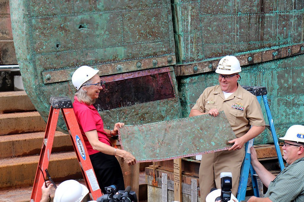
-
Hi Dave, You bring up an interesting subject. Doing some independent research on items like this rather than relying on information from a kit might be a good idea and probably fun to boot 😀. The replica of Endeavour does not carry stunsails from the topsails yards. The items on the channels are probably the lower stunsail booms. In addition to booms there are also stunsail yards to consider. Lees goes into great detail on the booms, yards, sails and rigging for the stunsails, but my apologies, way too much to copy here. Allan
-
Accurate copper plating
allanyed replied to allanyed's topic in Building, Framing, Planking and plating a ships hull and deck
Gregory, The 1" wide tape would be perfect for 1:48 when cut into pieces 0.312" wide, but I wonder about the thickness which should be only about 0.002. I think the thickness, if not too much like armor as mentioned above, would not be as noticeable as the length and width and with the foil, the nail holes can be pricked if desired, or better left off altogether. Thanks for the update Druxey, much appreciated. Allan -
Accurate copper plating
allanyed replied to allanyed's topic in Building, Framing, Planking and plating a ships hull and deck
Thanks Druxey, I had no idea about the diagonal pattern. Mark, thank you as well. Actually I have no need on my current project, but was more interested in seeing if there was a source for those building models that would have plating (circa 1778 and beyond) as the plating that comes with the kits that I have seen in photos and in person are so unrealistic as to ruin an otherwise beautiful piece of work. I realize it is "to each his own" in the end, but some folks might be interested to know there are alternatives, so thanks again for your lead. I did look up Caldercraft/Jokita and Blue Jacket and I am sorry to say their plating is pretty far off the mark. Below is what Caldercraft/Jokita shows on their website and then I manipulated their plates to show what it would look like if properly overlapped. On the sketch I included the diagonal row of nails mentioned by Druxey and hope I got it right. The full jumble of rivets all over the plates on both the Jokita and Bluejacket plates probably never was actually done. Allan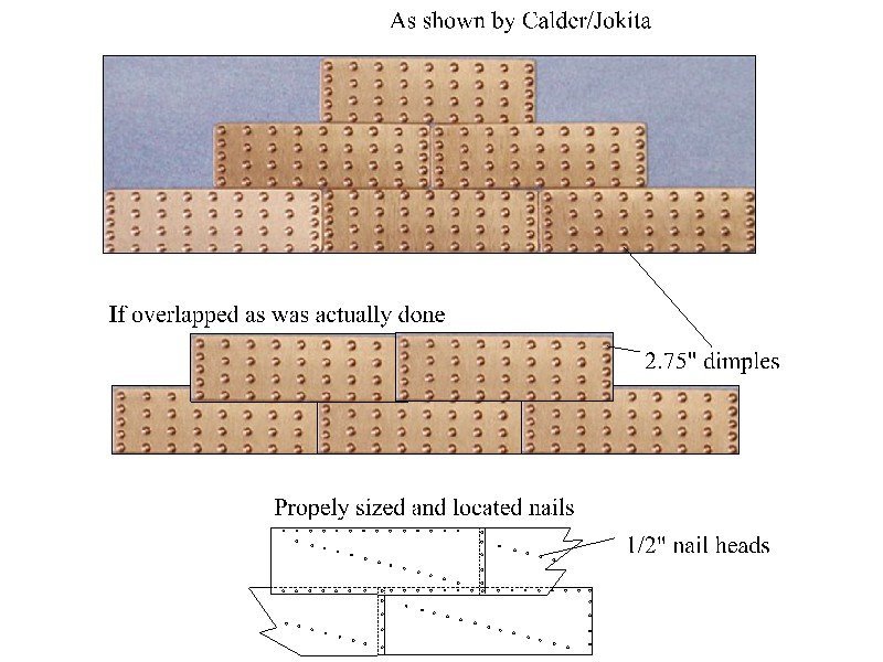
-
Who makes realistic copper plate material for ship bottoms for commonly used scales? Based on the build logs here at MSW, so far, I cannot find any kit manufacturer that supplies realistic plates. The plates are usually too large in general and always appear to have bumps that represent rivets or bolts which were never actually used. From a bit of research it appears, for British ships at least, the full plates were a nominal 48" X 15" and overlapped 1 1/2" so the 1/4" nails, (not rivets or bolts,) were hammered through two plates where they overlapped, both horizontally and vertically. The head of the nail was about 1/2" and the hammering would result in small indentations, not raised bumps, too small to see on scales smaller than 1:48 and even at 1:48 would only be about 0.01 in diameter. There were typically 16 nails in the long sides and 4 or 5 on the short sides. It seems plain copper plates with no nails would be a better way to go. Any information on realistic materials would be appreciated. The above information is from Goodwin's Construction and Fitting of English Ships of War, pp 226-7 Allan
-
Hi Jim and Jeff, Jeff, you mention rivets but unfortunately most kits plating is wrong as rivets were never used. Rather, nails were used with the dents going in, not sticking out. The photos in Jim's post above appear to have huge bumps sticking out. From Goodwin's The Construction and Fitting of English Man of War, pages 226-227 the plates were predominantly 4' 0" X 15" (0.75" X0.23" at 1:64) with a 1.5" overlap both vertically and horizontally. They were attached to the hull with sixteen 1/4" diameter nails horizontally and 5 or 6 vertically. The nail heads would be about 0.008" at 1:64 scale. It may be better that the nails are not even shown at this scale as they would be barely visible, if at all. I realize it is likely a kit error, but plain copper tape can be purchased to replace the plates from the kit for a more realistic look. Allan
-
Roger, very clever!!! We did this with bags of tent worms but had to run into the woods if the car stopped to raise some Hell with us. Hopefully the grandkids will look at the photo many years from now and show their own kids what great grandpa was willing to try. The green husks come off with a little effort but I defy anyone to crack the inner shell with a nutcracker. Two or three nuts will keep anyone busy for hours. I decent size vice does the trick though. (Chestnuts are easier) Allan
-
I agree with Eberhard. Clean surface and totally dust free environment, no wool sweaters (learned this from an esteemed builder/MSW member quite a few years ago). Spray paint in light coats (four or five) and if needed steel wool between coats, then several clear topcoats . Light spray coats should yield a flat surface with no bumps or runs if done correctly. NEVER start or stop the spray on the model, but rather off to the side a few inches when beginning and ending the movement across the model. Of course spray methods need taping and such to block any overspray. Allan
-
This is more of "what if" post as I think getting this wood from my new found source could be problematic. The kids and grandkids took us to a dog park in Leavenworth, KS over the holidays and it was in a grove of eastern black walnut trees. The ground was littered with thousands of nuts. VERY hard to get open, but when you do, tasty as can be. These are walnut trees, not the trees from which the brittle grainy stuff is harvested for kits. Pics of part of the grove and this old man up one of the trees with two of the grandkids. Proved a point that one is never too old to do stupid things like climbing trees. Allan


-
Bill, I don't know about the Benjamin Latham but there are a lot of wonderful photos as well as drawings of the schooner Effie M. Morrisey on the Library of Congress website that may be of some help to you. I would suggest you get a copy of the American Fishing Schooners 1825-1935 by Chappelle. I find it a pain to use at times as there is no true index, but it is far superior to the McManus book regarding details. Allan
-
Greetings to MSW/NRG Members and All Ships at Sea
allanyed replied to Michael Scarborough's topic in New member Introductions
I am EXTREMELY happy that you posted this and VERY impressed. One of our illustrious members and well-known ship modeler and author was a set designer and will enjoy seeing this. It is amazing how diversified the backgrounds are for our membership here at MSW. THANK YOU FOR POSTING THIS!!!!!!!!!!!!!! Alsln -
Greetings to MSW/NRG Members and All Ships at Sea
allanyed replied to Michael Scarborough's topic in New member Introductions
Michael, I look forward to your videos and of course y our build log! I will do some researching on Weill's music in the meantime. Hope it is not as heavy as Wagner!!! Allan -
Greetings to MSW/NRG Members and All Ships at Sea
allanyed replied to Michael Scarborough's topic in New member Introductions
First, welcome!! Second, WOW on the models and such!!! Third, SUPER WOW on singing opera!!!! Tenor? If you have video of any of your own performances please do post. I had to go watch one of my favorite arias once you posted as it has been a while. La Boheme BEST ARIAS - Montserrat Caballe and Jose Carreras in Barcelona 1980 - Bing video Allan -
Treenailing at 1:48 can be a beautiful thing or as stated above it could look like the hull has a bad case of the measles. When your drill bits are in hand, drill some test pieces. Rub a touch of PVA in the holes and sand by hand or with a light touch of a vibrating mouse type sander to fill the holes. Let it cure then apply whatever finish you plan to use, be it an oil or poly or whatever. I have done this with castello and it give a very subtle look such that you can see them, but they do not jump out at you. I would suggest bamboo which I love as the color is also very subtle, for castello and boxwood, but may be too stark of a contrast to cherry. Looking forward to your test results. Allan
-
Ditto to Kirby's post plus David Antscherl's article on spiling planks. Study a couple contemporary planking expansion drawings which are easily found on the Wiki Commons site and at RMG Collections site. For what NOT to do, look at build logs here at MSW as some show what happens when following kit directions that often provide other than realistic results. Happy New YEar Allan
- 362 replies
-
- 1
-

-
- Amati
- Lady Nelson
- (and 2 more)
-
Wecome JGR! Where are you in FL? Happy New Year! Allan

