allanyed
-
Posts
8,149 -
Joined
-
Last visited
Content Type
Profiles
Forums
Gallery
Events
Everything posted by allanyed
-
 Hi Edward No harm especially as they are on the lower deck. For the upper deck, they are likely set up with two single blocks with the line attached to the block hooked to the bulkhead ring, then run through the blocked hooked to the ring on the carriage, then back through the sheave hole in the block at the bulkhead. Following is a rough picture, thousand words, yadda yadda. Allan
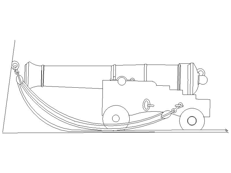
-
The Vanguard yawl hull looks really good. (I assume it is a yawl as it is clinker built) As the boat will be sitting right side up, are the thwarts, knees, supplied with the hull or will you be making and installing them? I looked at the Vanguard website but only see the hulls. Will you also be including the longboat and pinnace which 6th rates carried in her time? Allan
- 542 replies
-
- 2
-

-
- Sphinx
- Vanguard Models
- (and 3 more)
-
Welcome from a former US merchant mariner!! Allan
-
Detail sander from an electric toothbrush
allanyed replied to grsjax's topic in Modeling tools and Workshop Equipment
Time to replace the old one which will become a sanding device momentarily. Thanks for the tips guys!!!!! -
Tom, I TOTALLY agree with you. Do some kits give instructions to lay the planking like this? It is not remotely close to how the hulls were planked and as a result, the appearance of many otherwise extremely nice models are ruined with this fantasized style of planking. There is ton of information here at MSW on properly planking a hull so really no reason not to do it accurately. Allan
-
Mondfeld v Lees Masting and rigging
allanyed replied to DaveBaxt's topic in Masting, rigging and sails
NEVER too late. I think that you or anyone can wind up with a beautiful model if one does not rush or settle. For many members, it is better to build one really good model over several years than pump out a mediocre model every year or so. Keep in mind that do-overs are a part of this hobby for both the newest and most experienced and there is nothing wrong with that. Needing a do-over and ignoring it is what yields models that are not so nice. Most members and of course the builders of the contemporary models that we see never had the training aids we have today. Any member that wants to improve can do so with the help of so many people and so much information right here. Allan -
Mondfeld v Lees Masting and rigging
allanyed replied to DaveBaxt's topic in Masting, rigging and sails
Toys maybe, maybe not, but I think you get my point. If you are going to spend the time and expend the effort to build a model, why not make it as good as possible, be it scratch or bashing the kit by replacing out-of-scale and otherwise inaccurate items like belaying (bowling) pins, gratings, and copper sheathing. Just one opinion. Allan -
Mondfeld v Lees Masting and rigging
allanyed replied to DaveBaxt's topic in Masting, rigging and sails
David 1. Caldercraft- a toy model ship kit maker. They were actually awarded awarded a gold medal at the Nuremberg Toy Fair in 1984. 2 Lees and Monfeld - Researchers. In the end it is up to you to choose any of the above, but I have never seen kit makers quoted as a source of accurate information. Allan -
Less costly rigging rope for Pride of Baltimore II?
allanyed replied to Brewerpaul's topic in Masting, rigging and sails
Paul, I am with Azzoun. There was a post in the past few days showing a home made rope walk that could help you. Even if it costs a bit to make, you will save in the long run as you can make any size rope you want (most kits relegate you to only a few sizes and many don't even have the correct color, especially including black standing rigging) There are many sizes of cordage on any given ship so the walk will allow you to make as many as your vessel used. Allan -
Interesting subject Kevin. I remember studying these ships in the Naval Architecture class and wish I still had my old books, but do not recall this subject (it has been close to 60 years) I did find this paper which is quite interesting but see nothing about the rudder design to help you, sorry. https://ww2.eagle.org/content/dam/eagle/publications/company-information/workhorse-of-the-fleet-2019.pdf
-
Rob, Kudos for your efforts! Perhaps a smaller, better quality kit, would be a better way to go in the future. Study photos of contemporary models on some of the details. For example, the battens on the grating should be running fore and aft and the ledges athwartships rather than the other way around. The coamings and head ledges do not have 45 degree cuts on the ends, but rather the head ledges and coamings are mortised so the head ledges rest on top of the coamings. All comes from doing a little research, which can be a lot of fun, rather than guessing, or worse, relying on instructions from most kits. For planking, you might want to consider studying the tutorials here at MSW before attempting the next planking job. Keep at it and take joy in the project! Allan
-
Welcome to MSW Steve!!!! Please post an intro with a little about yourself on the new member forum. Allan
-
Bluenose keel help
allanyed replied to majkowskyj's topic in Building, Framing, Planking and plating a ships hull and deck
Hi R Thank you very much for your post to John, that was very kind. Welcome to MSW. It would be a polite thing if you would post an introduction and a name on the new member forum so we get to know a little about you. Allan -
Jackson Three months too late?? That is not really that much time lost to do things correctly, but most of us (me included) have been guilty of being too lazy to make things right at times and then regret it later. Allan
-
First, I hope this is the right forum to address movies. If it is, hopefully a mod will change the title to include movies. If not, where should it go? In any case, has anyone seen North Water and if so, what did you think? I was going to watch it but have to subscribe to AMC+ which carries it and want to avoid this if the movie is not very good. TIA Allan
-
- 1
-
-
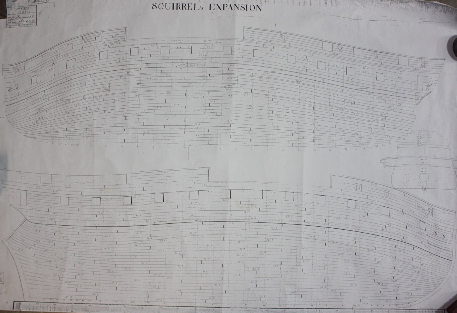
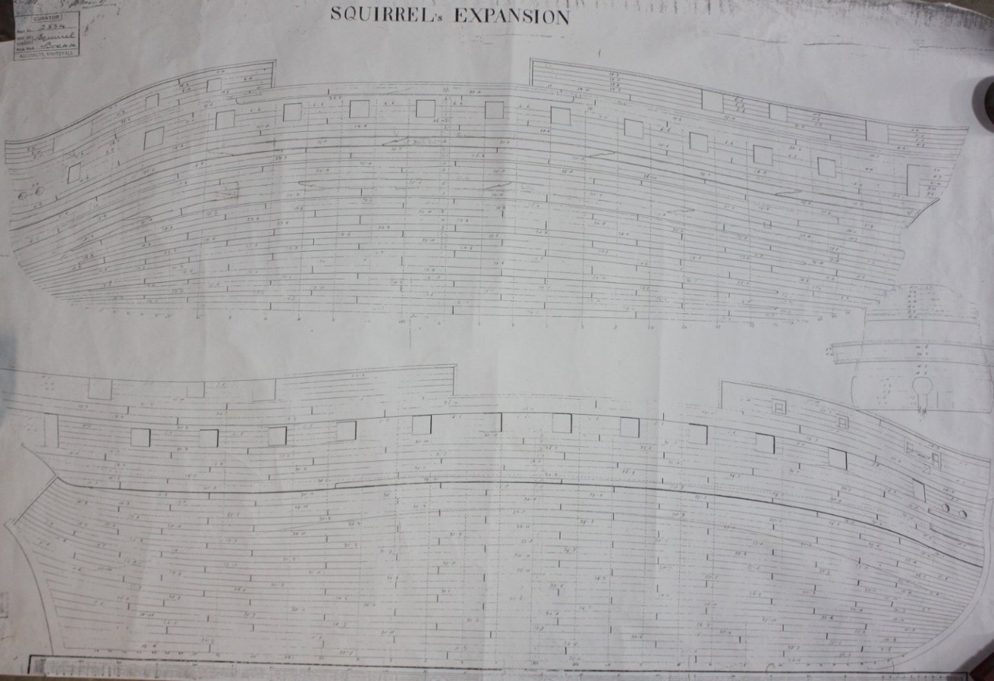
The forward portion of the planks are supposed to taper to about half the width that they are midships. You need to mark out with a tick strip the width of the planks along each bulkhead to get them exact. If you study the planking tutorials here at MSW and look at a few build logs you will see what I mean and they will help you wind up with a very nicely planked hull. The planks should not bend as you have them. The first layer of planking is actually closer to how they should look. If you study a plank expansion drawing as well, it will give you an idea of the shape of the planks. One example is below (the outboard planking is the lower drawing) and there are a few on the Wiki Commons site as well as at the RMG site. As to finding wood, I will be very surprised if anything you find is a good color match to the material you already used. I hate to say this (and this is just one opinion thus probably not worth a whole lot) but you are probably better off to remove all the second layer planks and start over with better planking material such as Alaskan cedar, Castello, or some other close grained wood rather than the wood that you have which is extremely grainy. Allan
-
How many kits do you have on the go at the moment?
allanyed replied to CaptnBirdseye's topic in Wood ship model kits
Rockinbudgie, For the cost of those kits one could have purchased a shop of top quality machines and materials and build models that would be far and away better than any kit, PLUS, there would be hundreds of choices of vessels that few, if any, have ever built before. Then again, why do many of us insist on buying more and more books when we usually use no more than a half dozen to a dozen of them even for scratch building? I guess we all have be a little nuts to be in this great hobby of ours. To each his own, and God bless us everyone.😀 Allan -
Mark, Fantastic information that is going into my data bank. Allan
-
The planking came out extremely well! What material did you use for the trennals? Allan
-
Your English is better than my French. Je parle en peu, mais ma femme parles en francais, donc voyager en France est plus facile quand on y est. Allan
-
She definitely has a fascinating history and your workmanship is very neatly done! Kudos!! Certainly not your doing, but with so much contemporary information on various ships' boats available, it would be a real joy if OcCre would do at least a little research instead of putting out their own ideas on what this famous boat looked like and how it was constructed. Again, I realize these are the kit maker's design mistakes. Allan
-
Hi Steve, I am not familiar with the Tally Ho project but am checking it out now. Thanx Allan
-
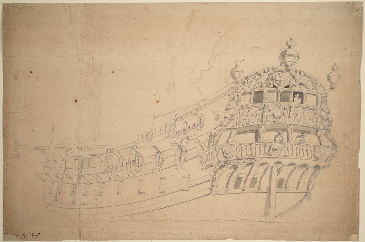
Michael Extant, I don't know, but do you have Richard Endsor's The Master Shipwright's Secrets? He has a lot of information on Mordaunt Between the various VdV drawings in his book and RMG you may be able to deduce the lantern sizes. What surprised me is that Endsor does not show the lanterns on his own drawings/paintings that are in the book. The following can be found on the RMG site as well and MAYBE could help. Allan
-
Robert, If you want to build a 74 with a book or full set of drawings, you may want to consider a French or English ship. Anatomy of the Ship series has the Bellona (1760) but you will still need a good set of drawings of at least for the body plan and profile which you can get from RMG Hopefully some member will have info on a book or set of drawings for a Spanish 74, but I do not recall seeing anything like what you want. Good luck with your search, it will be great to see if you come up with something. Allan
-
Rob, Madrid Naval Museum (museonavalmadrid@fn.mde.es) has what I believe are contemporary drawings of Montanes as well as written descriptions of her interior and other ships of her class. One drawing is available at RMG as well. https://www.rmg.co.uk/collections/objects/rmgc-object-79963, Regarding a book, are you looking for information on how to construct the ship from scratch? Ocre has plans for Montanes but after seeing photos of their model on their website one may wonder if accuracy was a priority for them. Allan