allanyed
-
Posts
8,149 -
Joined
-
Last visited
Content Type
Profiles
Forums
Gallery
Events
Everything posted by allanyed
-
 First, welcome to MSW Adrien. I could never live in Bordeaux as I would spend all my time and money in the wineries on the left bank of the Gironde!! 😃 Regardless of this peril, we hope to spend some time in at least one or two regions of Bordeaux on our next trip to France. Please post an introduction about yourself in the new members forum, including your interest in this subject. Others may also respond with help for you. You can purchase at least one log from RMG . https://www.rmg.co.uk/collections/archive/rmgc-object-529446 Have you PM'd Frollick? Just click on his name then click on message and send your note to him. Encore, bienvenu to MSW Allan
 -
I love the lights Edward! A question, hope you don't mind, is the cannon/carriage construction and their rigging what is instructed in the kit? The reason I ask is that the running out tackle has the double and single block on each side reversed compared to what is normally seen. Thanks Allan
-
Bob, Not sure what you mean that MSW has a copyright on a drawing. I may very well be wrong but I don't think MSW (Model Ship World??) owns any drawing copyrights. Interesting project though. Have you contacted the NYYC? They have hundreds of schooner models including cup racers and may be able to help you. I would you give you some contacts but I have not been to visit them for quite a few years so have lost touch. The Library of Congress is also a possible place to look if you have not already done so as well as the International Yacht Restoration School, in Newport Rhode Island where someone at that school may be willing to give you some help. Allan
-
Welcome to the fray Steve, Have you ever had a chance to trek down to the Bristol Marine yard in Boothbay where they are rebuilding the schooner Ernestina? Allan
-
Roger, you hit it on the nose, she only sailed a little over a kilometer (1300 meters) before going down. I wonder why anyone would want to build a model of her when her only claim to fame is that she was poorly designed. Walter, if you must rig sails, keep in mind she carried ten but they were never all set before sinking. Only four were set when she heeled over and took water through her gun ports and sank. I have no idea which ones, but you can probably find this information by contacting the Wasa Museum. A full description of the few minutes of her life under way can be found at https://www.vasamuseet.se/en/vasa-history/disaster Allan
-
Hi Marinus Does the kit have copper sheathing material or will you be using something else? The reason I ask is that most, if not all, kits with copper sheathing have the stuff which is not remotely close to being realistic and greatly diminishes the look of an otherwise beautiful model. There are alternatives that will avoid the measles look on kit supplied copper materials and has been discussed in depth here a MSW lately. If the plates in your kit have the phony bumps that are supposed to be bolts or rivets, PLEASE look at the discussions because there were no bolts or rivets used, but rather nails that indent the plates, they did not stick out. At your scale they would be nigh invisible so probably better to use plain copper tape material with no fasteners indicated at all. Just as an FYI, the plates were about 48"X15" (0.67"X0.20" at 1:72) if you want them to be to scale. These overlap 1.5" on one vertical side and on one horizontal side much like roof shingles. As a Victory fan, have you signed up for Adam Preston's TV series? Allan
-
Untangling and rerigging or start from scratch?
allanyed replied to Rgpracer's topic in Masting, rigging and sails
Gregory, Whoever drew this didn't get the word..😁 Another piece of contemporary evidence showing that there are few, in any, absolutes in the arena of ship building and modeling. Nice find. Allan -
HMS Bounty by AdamA - 1:48
allanyed replied to AdamA's topic in - Build logs for subjects built 1751 - 1800
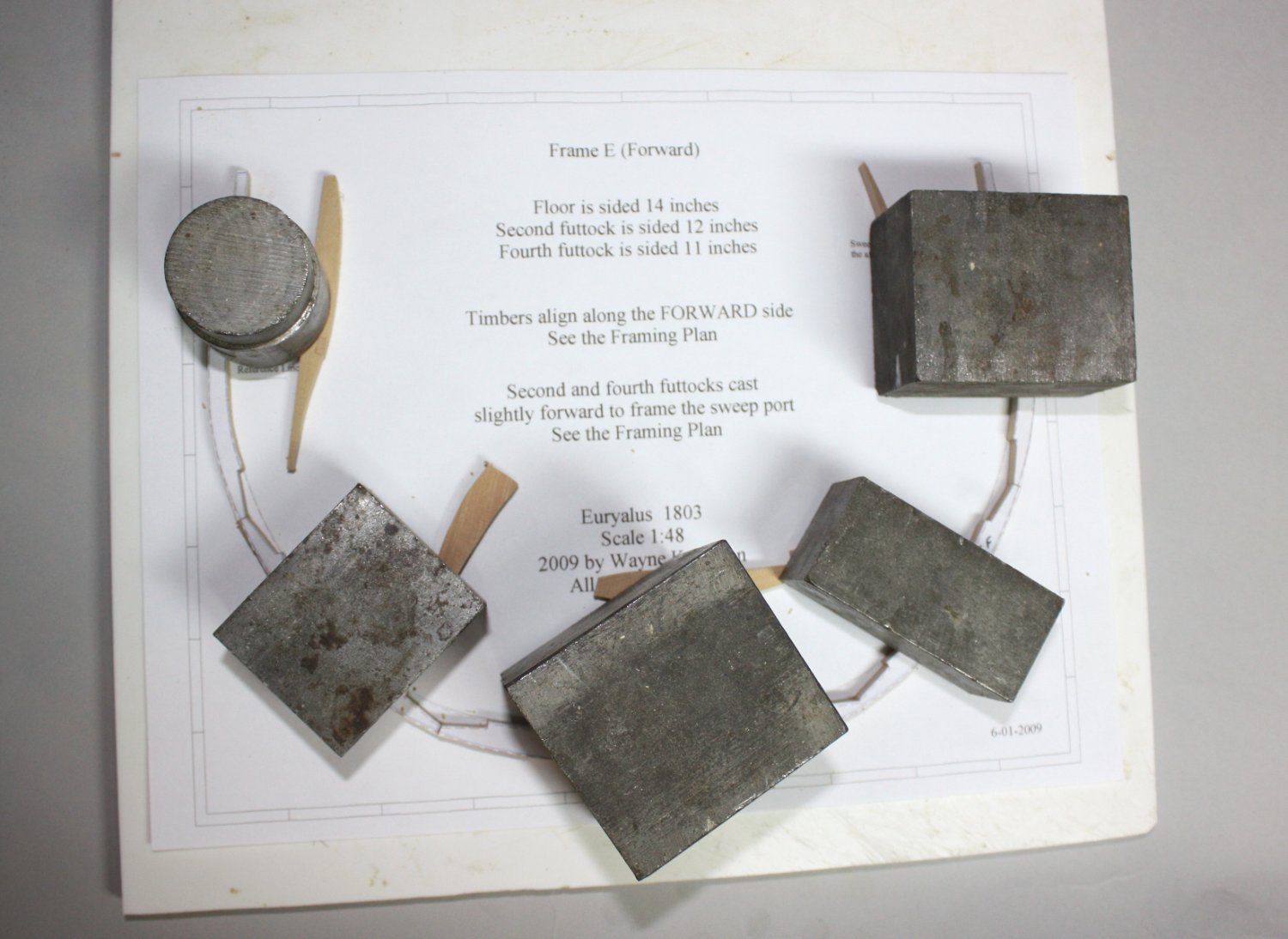
Please post your results and let us know how it goes. I am adding another photo we show in the Euryalus book and is a step I still often use. The blocks are scrap steel cutoffs that I got from a local machine shop for free many years ago and are still quite useful. There are pieces of scrap wood that you can see in the photo so the steel blocks stay flat on the futtocks. Allan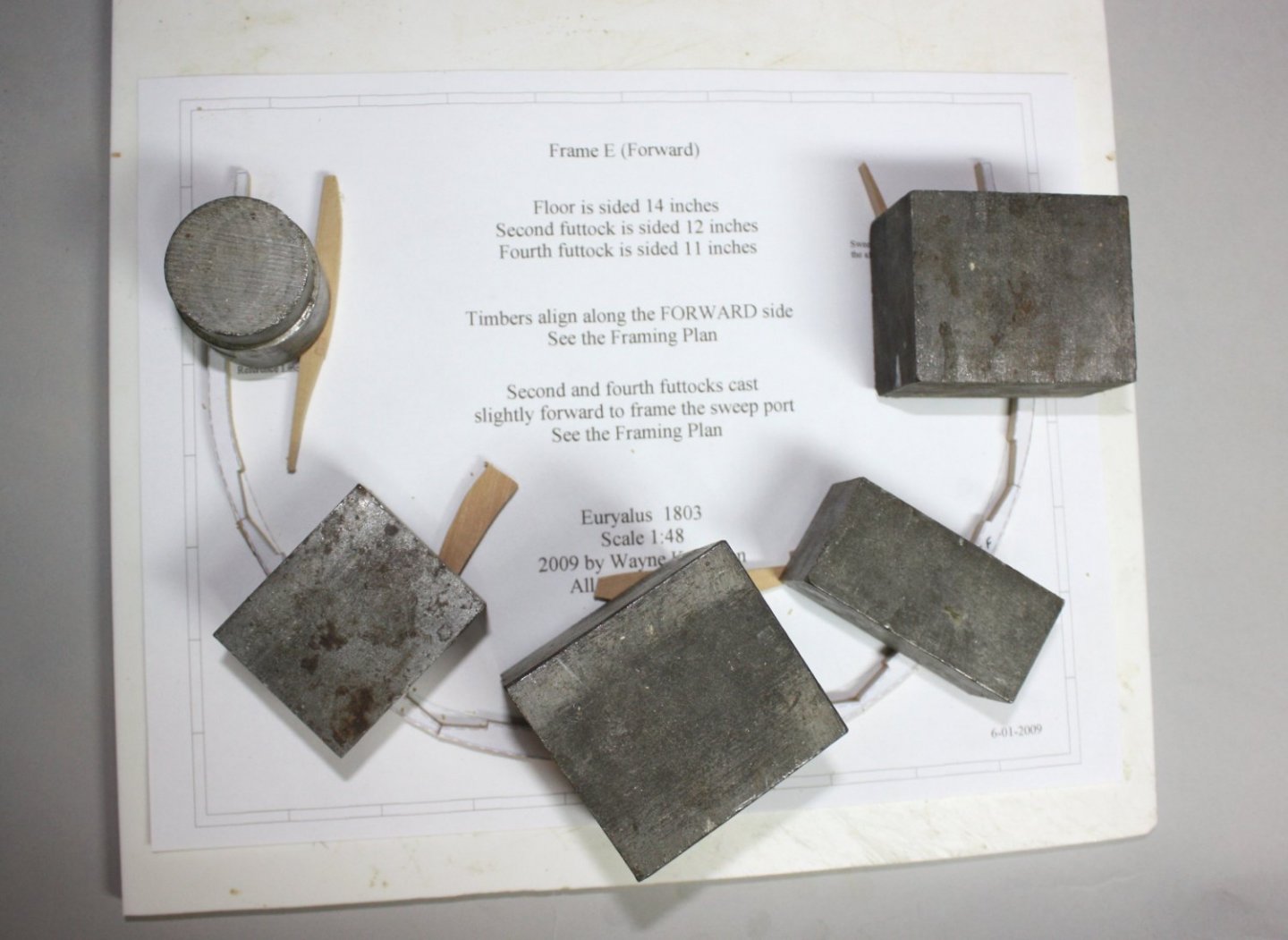
-
Hi Jeff, Very neatly done overall, congrats!! Just wondering if the ship's boat sitting upside down is temporary. Your copper sheathing is very nicely done but I do wish some kit maker would provide realistic looking copper sheathing materials. They all seem to be upside down like yours, showing what look like rivets instead of tiny depressions from the nails that were used and no overlaps which was done in actual practice. I realize this is a kit thing and not your doing, but one of these days hopefully some kit maker will get it right. At your scale, it would probably be better if the kit makers did not try to simulate a 1/4" nail with a 1/2" head (0.007" at 1:70 scale). As an obvious fan of Victory and Nelson, I hope you have signed on the Trafalgar project detailed in my signature below. Thanks for sharing your work on your build! Allan
- 49 replies
-
- 1
-

-
- victory
- billing boats
- (and 1 more)
-
HMS Bounty by AdamA - 1:48
allanyed replied to AdamA's topic in - Build logs for subjects built 1751 - 1800
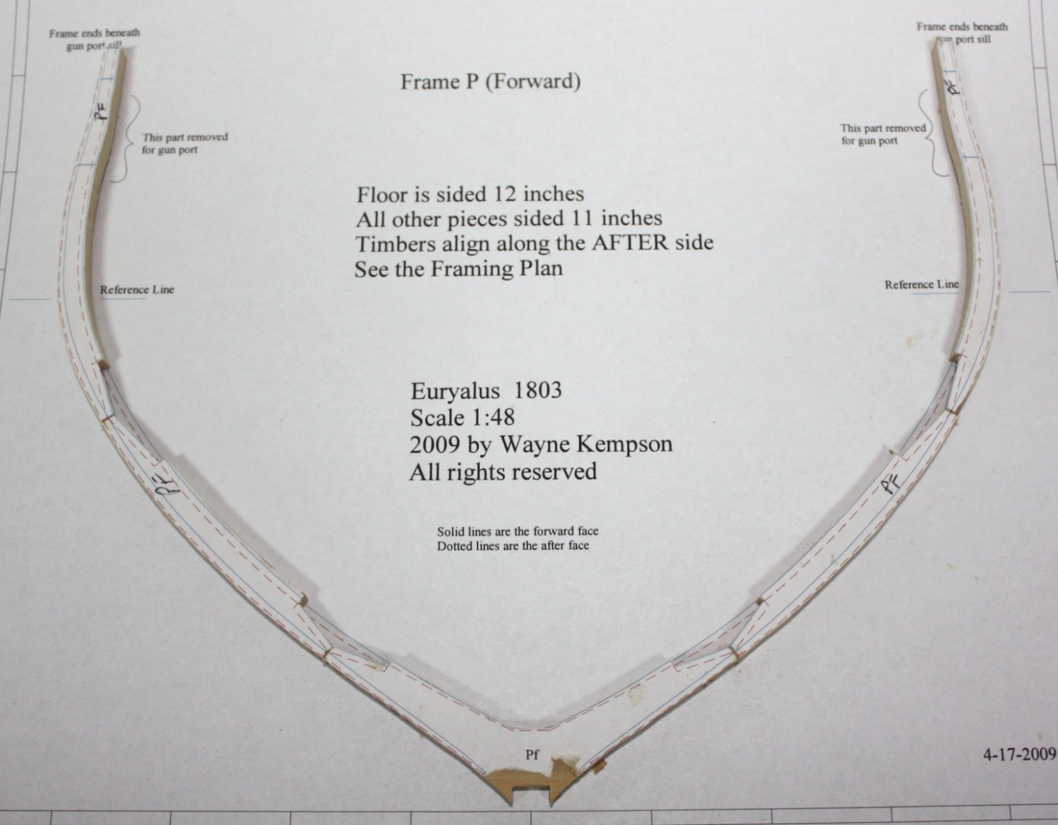
Just a thought when assembling the futtocks and floor and such.... When I print out the individual frames, I print one on label paper which will be cut into pieces and stuck on the pre-thicknessed pieces of wood and a second print out on plain paper. When assembling and gluing, it is done on top of the plain paper copy so I know that they are perfectly aligned. Allan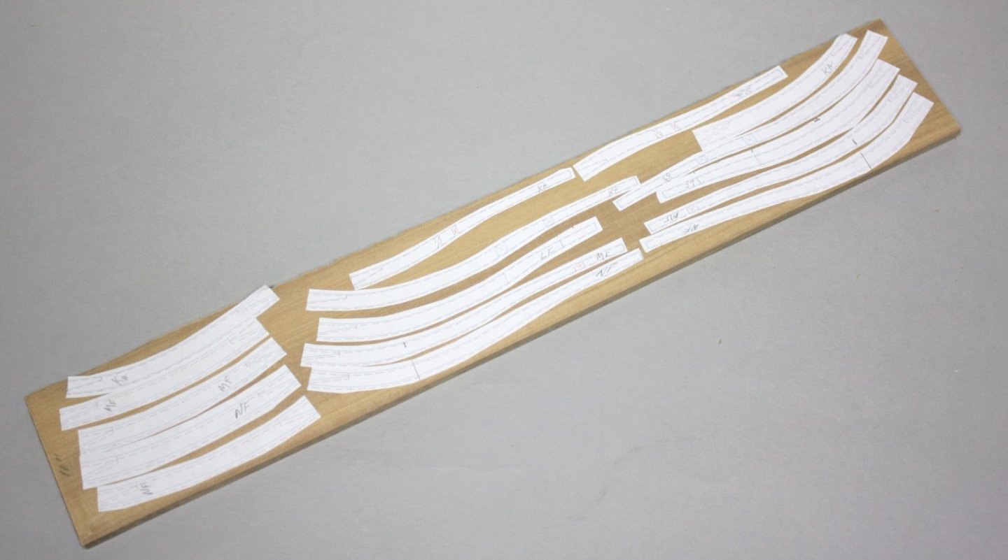

-
Hi Dave, Just an FYI, hope you don't mind. While the fictional ship Surprise (based on the Rose) would have had her name on the stern due to the time period, and while most kit makers have the name on the stern of every vessel (which is usually not appropriate) , Diana 1794 would not have her name anywhere on the ship. As you have been so meticulous so far, in case you did not already know, I thought you might be interested as there were no names on British warships except between 1780 and 1790, and then they were painted on, not made of wood. They were typically found on the counter below the lights (windows), not above the lights as shown in the photo in the post from last year. Cheers Allan
-
Emil First, welcome to MSW. When you have a moment, please post an introduction on the new member forum so we can get to know a little about you. When you say "this model," are you talking about the Bounty at 1:50 scale? Regarding the copper plating, most, if not all, of store-bought plating is out of scale and appear to have rivet bumps rather than nail indentations. Making your own is probably the best way to get them right. Not knowing for sure your scale, the full size of the full plates on British ships was typically 48" by 15" and overlapped 1.5" If your scale is 1:50 the plates would be 0.96" X 0.30" with an overlap of 0.03" . The nails were 1/4" with 1/2" heads so if you feel you must show these dents (NOT bumps), they would be about 0.01" diameter at a scale of 1:50. If you have not already done so, do a search here at MSW on copper sheathing as there has been a lot of discussion over the past month or so regarding the plate sizes, plate overlap, the nail patterns and spacing, etc. You can buy copper self-sticking tape so you don't have to glue and paint aluminum foil. Allan
-
Dusan, Lovely build overall, and I admire you bashing to get things even better than what the kit provides! The upper decks' gratings are extremely well done, with the battens running fore and aft rather than athwartships. Allan
-
No one famous (except for this saying) This modern version is attributed to American ad agency exec, Fred Barnard. It is a paraphrase of several earlier versions. Allan
-
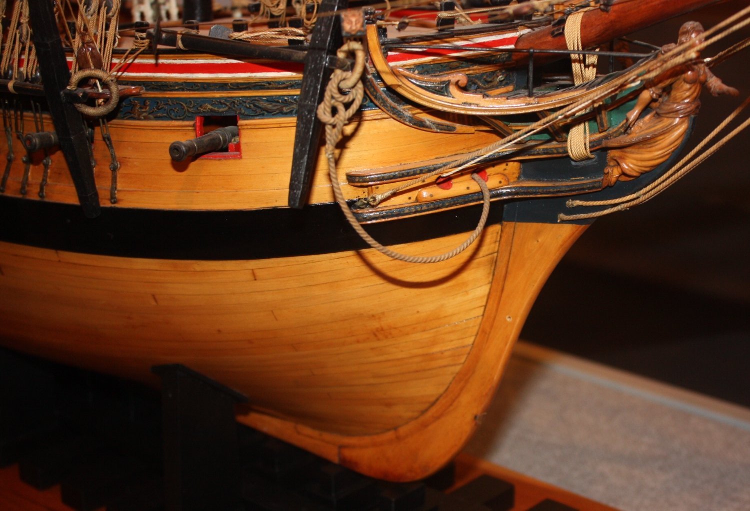
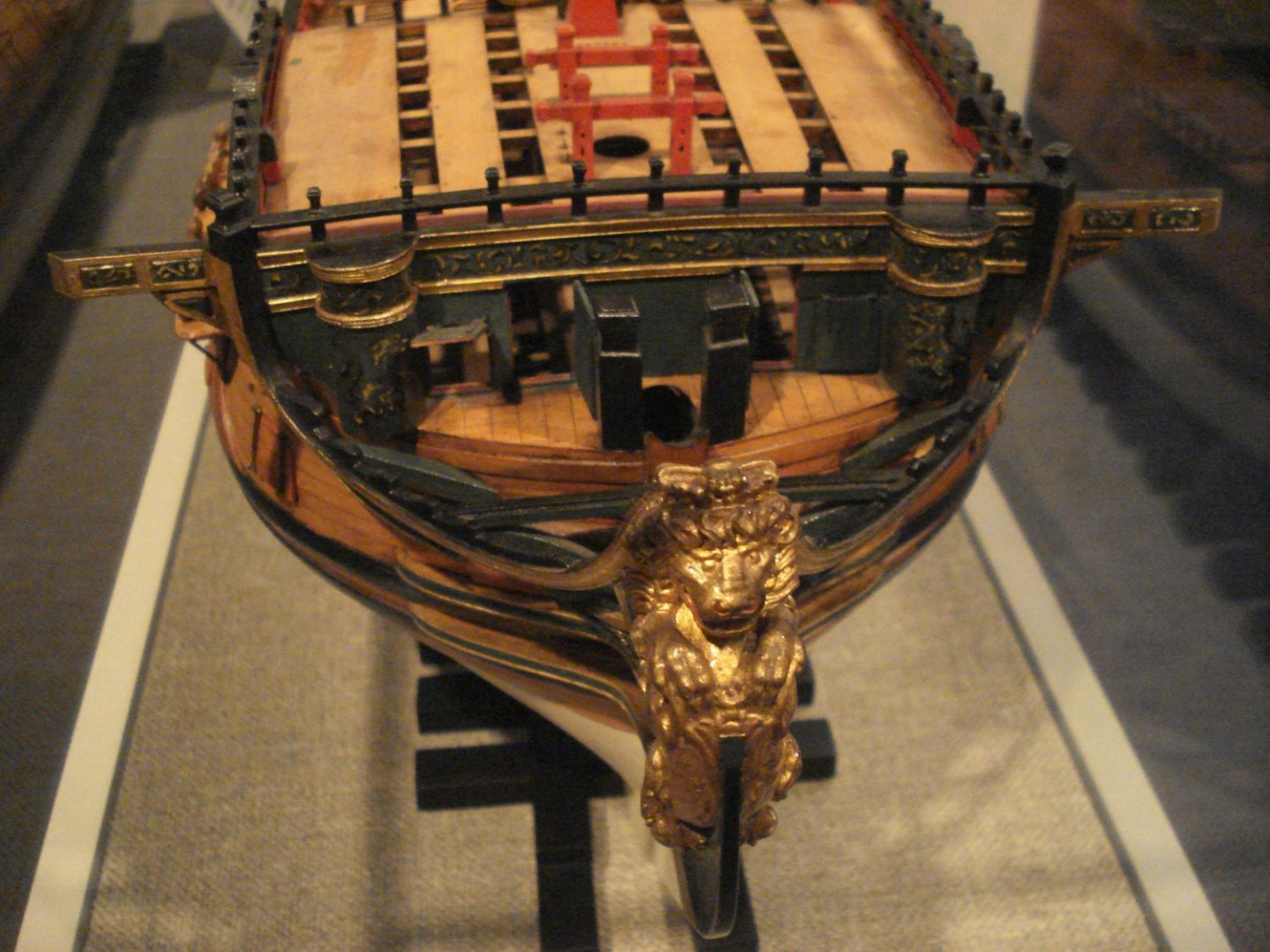
I do have a question regarding the forward most part of the knee of the head. The sketch I posted shows a radius on the forward face, but I have seen contemporary models with the radius and other without. Like most things in our hobby, not much is cast in stone, but I was wondering if the radius was era related or decided by the shipwrights. Two photos below, one with no radius, the other showing the radius at least below the figure head. In the second photo I do not recall for sure if the radius followed all the way up to the figurehead but I think it did in this case. Allan

-
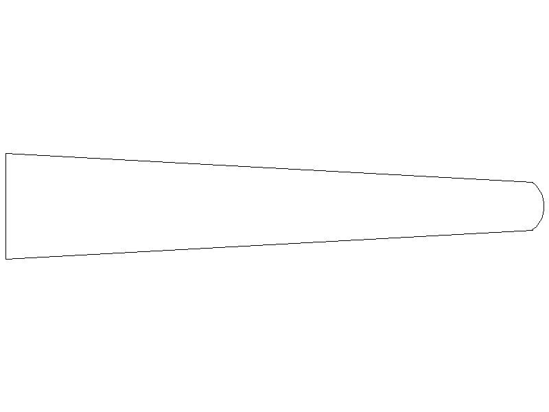
JJ, The area to be cut out in the photos does not look right at all. It looks like they show a gap to be cut out that is much too wide. There is a taper from the stem as you move forward to the knee of the head where the figurehead rests. I don't have access to my books for a couple days, but if I recall correctly, I believe it tapers to about half the width of the stem. The top view rough sketch below is not to scale but pretty close. This means the cutout in the figure head needs to taper as well for a proper fit on the knee of the head. Allan
-
HMS Euryalus 1803 by rlb - 1:48 scale
allanyed replied to rlb's topic in - Build logs for subjects built 1801 - 1850
Ron, I wish I bought a dozen copies myself when I see prices on the net as volume one is out of print. I'm glad Wayne and I were able to help. If I spot a copy at a realistic price I will PM you.- 122 replies
-
- 4
-
-
- Euryalus
- Plank-on-frame
- (and 4 more)
-
Babyluca Welcome to MSW!!! Maybe it's me but I thought this was a strange introduction to yourself for a first post which is the purpose of the new member forum. Consider trying a search in the appropriate forums for this kind of information as you have questions down the road, you will probably get more responses. The new member intro forum is probably not the best place for this kind of question. Allan
-
Matiz Looking forward to your next post and photos!! We are scheduled to dock (Celebrity Reflection) in La Spezia September 25th. I know Pisa is not too far and if you have some time, I truly hope we can meet and have lunch together, (and maybe see Euryalus😀) Ciao Allan
-
Hi Mick, Are you referring to the spread sheets by Danny Vadas when you mention the set of tables? I have found these by Vadas to be reliable except for part of the 17th century where the data is all wrong as the initial formula he used was incorrect. Otherwise, the Vadas spread sheet is based on the formulas and ratios in David Lees' book. The mast lengths in this spread sheet are based on Lees' formulas and the lower masts are based on the length from the step to the top of the mast. Allan
-
Harold Hahn method
allanyed replied to Essayons's topic in Building, Framing, Planking and plating a ships hull and deck
Druxey Your photos bring up a very important point regarding the huge waste of wood when using the so called Hahn method. I built one model with this method many years ago and the cost of material for the framing was triple that of the method that you show and double that for a fully framed model. With the Hahn method, gluing overly sized pieces into sandwiches then cutting out the frames is expensive and considering the cost of quality wood today, the savings of using more traditional framing methods is significant. Allan -
Konrad Welcome to MSW. We have MANY members in which English is not their first language and they are active participants at MSW so you have no worries. Your English is better than some of us where English is our first language 😀 Allan
-
Welcome to MSW Julian! Being only an hour or so drive to St. Michaels, I am surprised a skipjack was not on your back to school (of ship modeling) list 😀 Cheers Allan
-
Tom, What you say makes sense but I had never seen such a system based on contemporary sources. Can you share the contemporary source from the forum discussion that came up with this as it would be an interesting thing to add to a model if it was actual practice. Thanks again Allan
-
Thanks Tom, This was new for me I had only seen the cannon pulled tight to the bulwarks and the running rigging lines frapped. What the forum idea shows certainly would not hold the guns tight and keep them from running loose unless it was in addition to having the guns up tight and the lines frapped with the muzzle secured to the bulwarks as well. Thanks for sharing!! Allan