


allanyed
-
Posts
8,149 -
Joined
-
Last visited
Content Type
Profiles
Forums
Gallery
Events
Everything posted by allanyed
-

Schooner plank length
allanyed replied to alross2's topic in Building, Framing, Planking and plating a ships hull and deck
Thanks Al, Have you been in touch with Maine Maritime Museum which I think is part of or next to the current shipyard complex which consists of five buildings, all part of the original Percy and Small Shipyard? As these are 20th century, perhaps they still have scantlings and/or drawings that may be of some help to you. Other members here may have more details for you based on their own research. Allan -
Schooner plank length
allanyed replied to alross2's topic in Building, Framing, Planking and plating a ships hull and deck
Al Jaager makes excellent points. Are you talking about military, pleasure, fishing or some other type of schooner? English, American, Canadian, or??? If not a specific schooner, what size vessel? If you can provide these additional details, that could be a help in providing sources and/or details. Allan -
Working out the correct height of the masts from the Deck
allanyed replied to DaveBaxt's topic in Masting, rigging and sails
Let me know if the drawing below is readable for you. For a scale of 1:64 the main mast, from the upper deck to the top of the mast is 9.46" The mizzen is 6.77" from the quarter deck to the top of the mast. I am also sending via PM Cheers Allan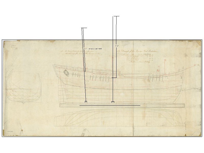
-
Working out the correct height of the masts from the Deck
allanyed replied to DaveBaxt's topic in Masting, rigging and sails
Dave I did not check but I assume Derek's figures are right . Using those 70'7" and 60' 8" mast heights from the steps to the top I superimposed these on the low res profile drawing of Endeavour from RMG so you can pick a spot on the decks from which to measure. Hope this helps. If this is not working, PM me and I can forward as an attachment. I can send in whatever scale you want. Allan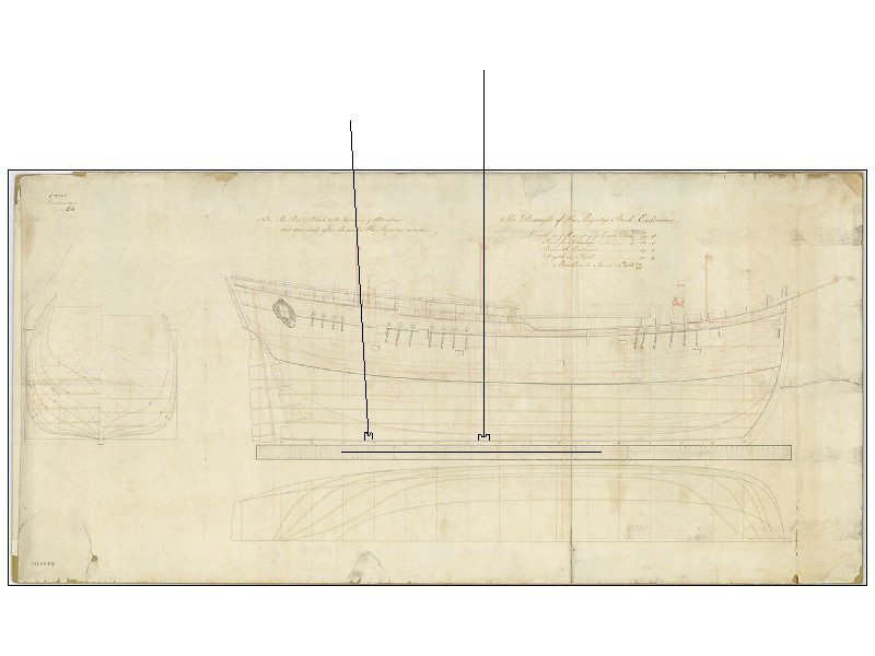
-
NAIAD 1797 by Bitao - 1:60
allanyed replied to Bitao's topic in - Build logs for subjects built 1751 - 1800
Your work should be an inspiration to all members. Looking forward to the next progress report. Allan -
Franz Romer and the most incredible sea crossing ever
allanyed replied to allanyed's topic in Nautical/Naval History
Me too ShotLocker. If you go by Patti's on Philadelphia Street say hello from an old fan of their hot sausage hoagies back in the late 60's. My admiral graduated from IUP in '70 so I had a chance to spend some quality hours there when coming to visit her. Allan -
This guy was something else! https://www.adventure-journal.com/2021/12/this-is-one-of-the-most-badass-sea-crossings-ever/
-
Thanks Vaddoc, much appreciated! Just as an FYI for the future, the planking should be 8 inches broad (0.80 inches at 1:10 scale) and 7/8" thick. I cannot tell from the photo but they look closer to 0.5" or 0.6" Of course sanding will take the thickness down so probably a non-issue. If you don't already have it, detailed scantlings for every part of the various types and sizes of ships' boats can be found in W.E. Mays book on boats of English men of war. There is a copy on Amazon for less than $10. Cheers Allan
-
Hi Vaddoc I like your build very much! Is this from the RMG drawing https://www.rmg.co.uk/collections/objects/rmgc-object-86936 for the late 18th century? Thank you Allan
-
Welcome to MSW Steve. You now have over 40,000 new acquaintances and friends. Allan
-
What you are saying Shipman makes a lot of sense, but in redrawing plans from RMG over the years I have found that they are often a bit distorted in one dimension or both due to folds and changes from aging. I always check the scale on the contemporary drawing and the called for length on the gun deck or other given dimension often found on the heading of the drawing, then insert the drawing into my CAD program and adjust the dimensions accordingly before having them printed or if I am redrawing them. I have found as much as a half inch differential in length of the drawing compared to the called for dimension on the original at times. I have no doubt the draftsman had it right when he prepared the plans, but 300 years can have its effect on the physical drawing. Allan
-
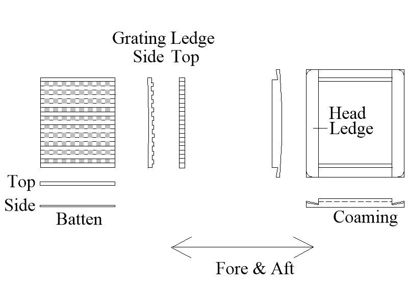
'Bug, I am enjoying your build log very much and kudos on some really fine work. I totally agree with Peter that the grates should be replaced. His photo shows the grating peripheral pieces nicely. It is usually the case that it is better to make the proper gratings as close to the size on the drawings as possible, then make the coaming and head ledges to fit the grating, not the other way around. This may put the assembly off by a hundredth of an inch or two, but will look much better. Don't forget that the head ledges rest on the coamings rather than the coamings on the head ledges. Sketch below may help a little. Allan
- 419 replies
-
- 5
-

-
- Victory Models
- Pegasus
- (and 2 more)
-
Hi Shipman The Imperial system is a relatively young system, not appearing until 1826 and is different in some ways than the previous systems of English units. English units were the the units of measurement in England up to 1826 when they were replaced by Imperial units , which evolved as a combination of the Anglo Saxon and Roman systems of units. Prior to the Imperial system various standards have applied to English units at different times, in different places, and for different applications. The two main sets of English units before the Imperial system was developed were called the Winchester Units, used from 1495 to 1587, as affirmed by Henry the VII, and the Exchequer Standards in use from 1588 to 1825, as defined by Elizabeth I. These English units were replaced by Imperial units on January 1, 1826 by a Weights and Measures Act which kept some but not all of the unit names and definitions. Allan
-
Davyboy I cannot find what the difference in length is for British units and Imperial units but the British did not use Imperial units until the 19th century (1826) Honestly I do not know which measurements changed in 1826 when they went from English units to Imperial which of course changed again in 1965 to metric but I would like to see what the differences are if anyone knows. I did a lot of searching but only found a reference to a pole standard of 6 feet based on outstretched arms of a 6 foot tall person, nothing about how long an inch is in English units versus Imperial units. Maybe they were the same, but ????? I suspect for our purposes there is little or no difference, but if anyone can share their knowledge on this that would be great. TIA Allan
-
Very happy to see another new member, welcome!!! Allan
-
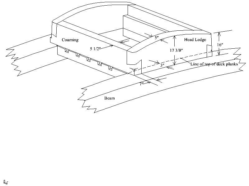
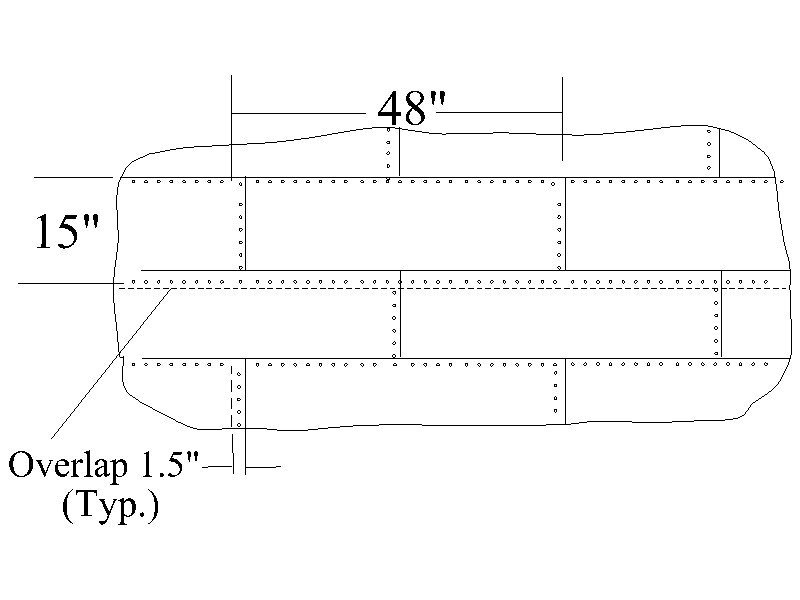
Sorry for the very late reply David, Yep, I was referring to the red linings. One thing to keep in mind for future builds. I assume the instructions were wrong or missing regarding the corner joints of the coaming and head ledges for the hatch openings. They were not cut at an angle, but rather lapped with the head ledges on top of the coaming pieces. Not a huge deal as your joints look quite nice, but thought you might like to know for the next model, hope you don't mind me pointing this out. See sketch below. (ignore the dimensions as these were not for Victory. Again, for the future, the copper sheets overlap so there should be single rows of nails, not twin rows, both horizontally (about 30-36 nails) and vertically (about 10) . I am sure this is another kit error because someone at Caldercraft did not do a thorough research. There are very detailed drawings on page 225 in Goodwin's Construction and Fitting of Sailing Man of War. ( I would post the page, but not sure that is permissible so redrew part as below) Some feel it is probably better not to show the nail pattern at all at 1:72 😀 Allan
- 218 replies
-
- 3
-
-
- Victory
- Caldercraft
- (and 1 more)
-
The larger the scale, the easier it is to show fine detail and subsequently the more time that is involved to achieve it. Look at the one or two 1:24 builds here on MSW to get an idea of a REALLY large model. Classic British models were mostly1:48 but the contemporary model of Lady Nelson (your current build) at RMG is 1:32. Allan
-
Hi Dave I really don't know about kits as they are more of a modern convention using modern methods and tooling (and I wish we did the same and adopt metrics in the US), but if you are looking for accuracy in scratch building or kit bashing and can find contemporary drawings for English ships up to 1826 they are usually 1/4" = 1 foot in English units. FWIW The English units were replaced by Imperial units in 1826 by a Weights and Measurements Act. There are other contemporary drawings I have seen in 1/2" = 1 foot and 1/8" = 1 foot. The British Establishments, The Shipbuilder's Repository, Steel's Elements and Practices of Naval Architecture and more, also use English units. An interesting thing I found is that the contemporary model of the LN at RMG is built to a scale of 3/8" = 1 Foot but when RMG gives the dimensions of the model in the description they are in metric. https://www.rmg.co.uk/collections/objects/rmgc-object-66562 Allan
-
DO, A cringle is a hole along the edge or in the corner of a sail, rimmed with stranded small line. Metal grommets are sometimes used as part of this as well. The fact that you are asking if someone sells holes (cringles) makes me wonder if you are asking about the grommets or something else altogether. Probably just a little bit of language confusion so just thought maybe you can clarify. Hope all is well in Madrid!! Allan
-
Thanks for signing up and I am glad to have helped, even if only in a small way. Allan
-
Juraj, Sorry to say but Amati does not always provide materials to scale. I hope this is not the case for the sail material, but if it is woven it will probably not be to scale. Plus, if it is cloth and you need to sew seams and such, there is no way to stich at scale that I have seen. Cheers Allan
-
Why masts are square at the top?
allanyed replied to Tommy Vercetti's topic in Masting, rigging and sails
The above mentioned books are great if you have them but there are a lot of contemporary drawings on the RMG Collections website on masts and yards that can be downloaded for free in low resolution. There also a number of high resolution contemporary drawings from RMG on the Wiki Commons site for various ship sizes and eras. Most of the high res are about 75 mb so cannot be loaded here. Two examples from 1780 that are only about 30mb each follow. Allan.thumb.png.95109ef10c163ab243933cd25e3e4fe8.png)
_RMG_J7602.thumb.png.a191c9fd2f177e4930376aed735dd6a9.png)
-
Thanks Mark!! Is the 4mm with the planking or just the top timber itself? OC, Sorry for the confusion, my fault. I was only looking at what the kit dimension was as it appears heavy in the photo, but I know what it should be based on the scantlings for the size of the ship and era. I was curious to see if Vanguard got it right as this is often wrong on some kits. The top of the top timber for the 1745 Establishment and again in the Ship Builders Repository (1788) and Steel's Elements of Naval Architecture (1805) show it should be about 4 inches, which would be about 1.58 mm at 1:64. If the total with inboard planking, top timber, and outboard planking are measured, they would total about 3.5 mm at 1:64. Allan
-
IF I am understanding you correctly Turbocad allows you pick the center, then a point on the arc, then the second point to complete the arc. They call it an arc center and radius function. Unfortunately, TC is not free but TC 2019 for beginners is cheap and may suit. Allan


.png.a494117e3c427fc98744d3f86927d392.png)
_RMG_J7602.png.91e63875f29d7169d4bcc6ad8151ee45.png)