
HOLIDAY DONATION DRIVE - SUPPORT MSW - DO YOUR PART TO KEEP THIS GREAT FORUM GOING! (Only 75 donations so far out of 49,000 members - C'mon guys!)
×


allanyed
-
Posts
8,149 -
Joined
-
Last visited
Content Type
Profiles
Forums
Gallery
Events
Everything posted by allanyed
-
 tom, Lovely build you have going, thank you for sharing. Hope you don't mind my question but you show something I have never seen before. Is this what the kit instructed? Thank you Allan
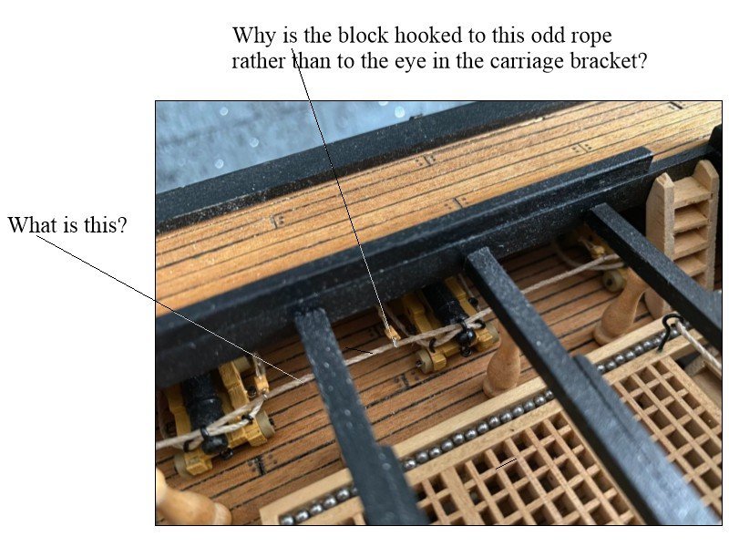
-
Harold Hahn method
allanyed replied to Essayons's topic in Building, Framing, Planking and plating a ships hull and deck
J Merton First, welcome to MSW!!! It sounds like you are referring only to the scantlings of the frames. These would be different for the Hahn method compared to a fully framed vessel. For British ships, scantlings cover pretty much every piece of a ship, not just the various parts of each of the frames. These dimensions changed over various periods of time and of course vary for different size vessels. A full set of scantlings can be found for the 1719, 1745, and 1750 Establishments, the Shipbuilder's Repository (1788) and Steel's Elements and Practices of Naval Architecture (1805). To the best of my knowledge, a complete set of scantlings is not available on the internet. If your ship was British and built in a private yard, there may be a contract available that also gives scantlings for the various pieces of the ship. If you are talking about an American vessel, the scantlings for an appropriatie period should be relatively close to the British. I PM'd you one folio from Scantlings of the Royal Navy Allan -
Hi BE, The ledges and battens seem about right, but I would have thought they would both be the same, i.e. 0.70 or 1mm which would be about 2"- 2.5" at full scale. I have no access to my books for another week so I may be off base regarding this dimension but I believe the battens, ledges and openings would be about 2.5"-3". This is something most kits get wrong, but again, yours look far better than any other kit gratings I have seen on the build logs here at MSW. Allan
- 857 replies
-
- 3
-

-
- Sphinx
- Vanguard Models
- (and 1 more)
-
Cutting out gunports
allanyed replied to Etcher's topic in Building, Framing, Planking and plating a ships hull and deck
Darren, Some builders plank the entire hull, then draw the gun ports in and I found that it works well for me. Once done, I drill a series of holes around the inside of the lines of the port with a tiny drill bit, then can cut the port, albeit undersized, with a chisel or scalpel. After the undersized port is cut, a chisel, file, sanding stick, whatever you are most comfortable using, can be used to take it right to the line. Bulkheads are a problem if the kit is not designed properly as they should not be in line with a port, just as no frame in a fully framed model or ship is in line with a gun port. One caveat, if your planking is the very porous and brittle common so- called walnut found in many kits, I don't know if any method will work well. Allan -
BE, Your model looks terrific and Vanguard seems to have gone out of their way to provide both quality material and accuracy. The gratings you have from Vanguard look far and away better than any other kit gratings I have seen. What is the width of the ledge and/or batten? You mentioned adding wood the thickness of the deck planks to the underside of the coamings and head ledges. I thought the head ledges and coamings sat on the beams and carlings, but in looking at a couple contemporary inboard profile drawings I am not so sure which, if any, was standard practice, sitting on the beams or sitting on the planking. I have no access to any of my books while traveling so hope someone here has a definitive answer. Thanks for sharing your build BE, this has been a really nice log to follow. Allan
- 857 replies
-
- 2
-
-
- Sphinx
- Vanguard Models
- (and 1 more)
-
Thanks Bruce, but I was only suggesting someone that has a copy of Lees handy post what the sail looked like for Dennis' project. We are traveling for 10 days so I have no way to look right now. What he shows may very well be the right shape, but as he took it from Steel, it is half a century later so maybe not accurate for 1745. Regarding the drawing you posted it looks like one of the Chapelle drawings of Mediator. This was one of the drawings that Carlosgf used for his build and shown in his build log here at MSW several years ago. His log may be of some help for Dennis. Allan
-
I do not have access to my books right now, but maybe someone else with a copy of Lees' Masting and Rigging can jump in to confirm if the shape of the sail is correct for 1745. Steel is early based on late 18th early19th century so there MAY be a difference in the shape. Allan
-
Hi Walter, Have you done a thorough search here at MSW? I believe this is discussed in some detail showing how to do that. I suggest you consider silkspan or similar unwoven material unless your scale is 1:24 or larger. No cloth exists for making sails to scale if your model is smaller, such as 1:48, 1:64, 1:98 etc.. Allan
-
FWIW, It would probably be easier and take less time to remove all the planks, throw them out and start over. You will NOT be the first to go this route and you will be very happy in the end that you started over. Study the tutorials before and during the planking process. Note that the aft end of the garboard strake should lay along the rabbet, same as the midships and forward part. It does not rise as you have it and this will create problems if you try to do this with the second layer. Study a planking expansion drawing as well to get a feel for where each plank goes. There are a lot of them on the RMG Collections site in low resolution. Go to https://www.rmg.co.uk/collections and type planking expansion in the search box . There are one or two in high resolution on the Wiki Commons site as well. Allan
- 362 replies
-
- 3
-
-
- Amati
- Lady Nelson
- (and 2 more)
-
Dave, Are those two planks glued in place or just temporarily in place until you finish shaping them properly so they don't ride up as they appear in the photo. You need to hot edge bend these per the method here (There are several videos) or spile as explained here https://thenrg.org/resources/Documents/articles/APrimerOnPlanking.pdf
- 362 replies
-
- 5
-
-
- Amati
- Lady Nelson
- (and 2 more)
-
Al, I now understand what you want to do and can relate in part. I have a set of planes from my paternal grandfather who was a cabinet maker from apprentice as a teen to doing restorations for museums and private individuals in his retirement years back in the 1960's and '70's. These are not quite so old as yours, but now probably over100 years old. have and use his workbench from circa 1920 and all will be passed down when the time comes. Imagine the stories these old tools of ours could tell if they could talk. Allan
-
Yves I THINK the most important thing about our own models is that we enjoy the entire process right up to and including end result which could include the research as well as the building for some. The learning process is never ending as I have learned here at MSW. Hardly a day goes by that there is not something new in "how to" or history, or off topic fun here. Allan
-
Just curious, but how old is the original material? If it is very old, I would think color matching will be impossble. Allan
-
This is very confusing. You say liners, but what do you mean, cruise ships or something else? HMS refers to RN vessels, not private merchant vessels such as freighters, liners, etc. What year?? There were no boats designated as life boats before 1790. From a few seconds of searching this popped up. The first boat specialised as a lifeboat was tested on the River Tyne in England on January 29, 1790, built by Henry Greathead. The design won a competition organised by the private Law House committee, though William Wouldhave and Lionel Lukin both claimed to be the inventor of the first lifeboat. There are images on the net as well. Allan
-
I am pretty sure the Bellona 1760 did not have a coppered bottom when she was launched as coppering was not standard until the late 1770s. Of course she could very well have been coppered later in life. It comes down to what era in her life that you want to represent including appropriate boats, cannon types (Armstrong/Frederick versus Blomefield) and so on. Same goes for having her name on the stern which some models show. This would be appropriate only from about 1770 to 1780. For your second planking, Chuck Passaro's write up is well worth studying for tapering and edge bending so you won't have to have the same problems as on the first layer. Allan
-
Pirate, as requested above can you be more specific? There is no such thing as an HMS jolly boat or HMS long boat. The old ships (HMS Bounty, Victory, or whatever) carried a variety of boats such as cutters, long boats, launches et al depending on the era and ship but no life boats per se. They were work boats used for various tasks but none were really meant to be used as life boats as we see on vessels in later years. Certainly they could be used as such, but was not the reason they were on board. Even on ships with 5 or 6 or even 7 boats, together they did not have the capacity to act as life boats for hundreds of crew members. The long boat for HMS Medway is a better, or perhaps, the best way to go for a start. Allan
-
BM Your post gave me pause so I just looked at photos of several dozen contemporary models at Preble Hall and more at RMG. I can find no rhyme or reason to the choice of colors on the furniture, or the bulwarks for that matter. Of course cost was a factor so black and red seems to be the most common colors where paint was used. There are some with hatch coamings and head ledges in natural wood, others that are black. Half the bulwarks are painted red, the remainder without paint of any color. Some have bitts and such that are predominantly red or natural, a few that are black. Some had a good amount of gold in the 17th century and into the early 18th century but this is pretty much limited to carvings. I also went back to a number of contemporary contracts and none had any mention of paint colors. What ship and year do you have in mind? Again, there does not seem to be a lot of consistency when looking at contemporary models (which more than likely have had their paint redone over the hundreds of years they have been around) so your comment on modeler's discretion, within reason, may very well be valid. Allan
-
1:98 HMS Victory plans
allanyed replied to Rgpracer's topic in Building, Framing, Planking and plating a ships hull and deck
Three sources are the 100 Gun Ship Victory Anatomy of a Ship by McKay, Longridge's Anatomy of Nelson's Ships, and RMG. There are nine low res contemporary draws of Victory 1765 on the RMG Collections website, any or all of which can be downloaded for free or purchased in high resolution as well in 1:48. These can be reduced at your local printer easily if you choose to receive them electronically. https://www.rmg.co.uk/collections/objects/search/ Victory 1765 You can probably reach out to Mantua as well but they may not be as accurate as the other sources. Allan -
Untangling and rerigging or start from scratch?
allanyed replied to Rgpracer's topic in Masting, rigging and sails
Longridge's book will be a great help in many ways, including how the shrouds were paired and set over the mast, how the ratlines were done, and much more. But, as you seem to be something of a detail minded person, or dare I say a bit of a perfectionist, I would invest in a copy of David Lees' Masting and Rigging English Ships of War. There are other books that members use as well and would recommend, but this one will get right down to the circumference of every piece of rope, how they rove, and on and on. You may want to check the masts and spars against the books to be sure the ones you have are the correct size and shape as well. You can also use the Vadas spread sheet here in the articles data base to get all the sizes of masts, spars, and ropes This is based on the Lees ratios. All you have to do is check the appropriate year and size vessel, type in the scale you are working, then 51.33 (the beam of Victory) in the appropriate box and all your dimensions will come up. https://thenrg.org/resource/articles You can also go to https://thenrg.org/resources/Documents/articles/TheArtOfRigging-Steel.pdf here in the articles data base for contemporary information. Allan -
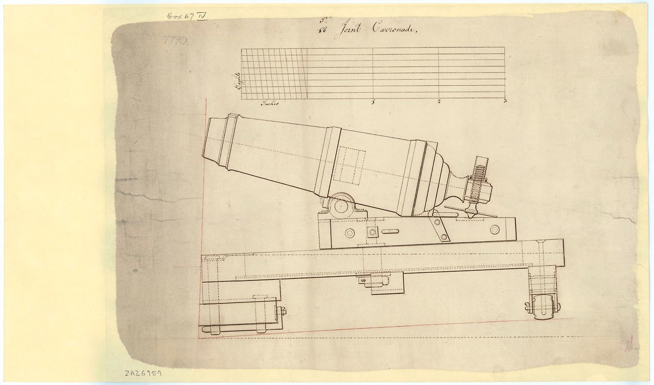
Per the earlier post, did you have a chance to research the above or try to contact Preble Hall at the Naval Academy? There are number of contemporary drawings over a span of years including the following joint type 18 pounder, circa 1790. Allan
-
Eberfhard, I just found out not too far back that Adrian Caruana passed away before volume three was published. British Naval Armaments ed. Robert D. Smith may be a substitute but reviews on this book that I have seen are average at best. I have found Caruana's information to be reliable and also wish volume 3 had come out. Allan
-
Chamfering Cutting Tool
allanyed replied to Dave_E's topic in Building, Framing, Planking and plating a ships hull and deck
Dave, A lot of builders here also scrape the entire hull and the decks before final sanding as well. Allan -
Pirate, this book is for sale as are the Caruana books, the information is not available for free as far as I know as it they have copyright protection. Allan
-
Chamfering Cutting Tool
allanyed replied to Dave_E's topic in Building, Framing, Planking and plating a ships hull and deck
Dave, The angle of the chamfer on every plank is dynamic but the tool has a fixed angle each time it is set so the angle will be wrong except for one small part of the plank edge if it used along the entire length of the plank. The same issue applies to the angle of the rabbet. A stiff back razor or any other hand held scraper blade can have the angle adjusted as you move along the plank when done by hand. Sanding will probably work, but for me, scraping is easier to control. The ROUGH sketch below explains it better (I hope). Allan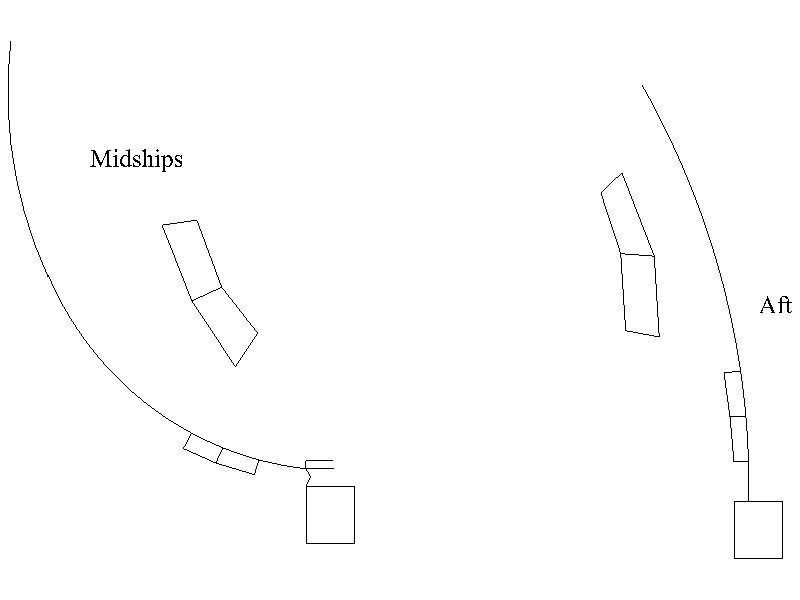
-
Edward There were changes to the capstans themselves at the time of your ship. I have no contemporary information on German ships, but about 1670 the forward capstans on British two deckers (from Deane's Doctrine 1670) had a single head capstan on the lower gun deck aft of the main mast and a double capstan near midships with one on the lower gun deck without a trundle head for bars and one on the upper gun deck that did have a drum head and openings for bars, quite different than what the kit drawing shows. I am not sure if a viol line (something of a predecessor to the messenger) was used at that time or if ships of your size had the hawser go directly around the lower deck capstan. Hopefully some members here have contemporary information on the proper rigging of the lines themselves. Allan