


allanyed
-
Posts
8,149 -
Joined
-
Last visited
Content Type
Profiles
Forums
Gallery
Events
Everything posted by allanyed
-
 The support piece is ingenious and looks to be a nice project in itself. Cudos!! Allan
 -
Tailing deck beams
allanyed replied to allanyed's topic in Building, Framing, Planking and plating a ships hull and deck
Thanks Mark. I was aware of a vertical score being made on the ends of the beams which I have done in the past, but not the horizontal and vertical intersecting borings. And you are correct, unless I was going to make beams from saplings, I will forego the practice of making sure the root end of the beam is alternating port and starboard. :>) Allan -
Tailing deck beams
allanyed replied to allanyed's topic in Building, Framing, Planking and plating a ships hull and deck
Photo record for sure Druxey. I am a LONG way from that point. In recently receiving the contemporary information from a contract for sister ships to Lichfield as mentioned above, I have had to edit many of the drawings, including every frame, and edit the scantlings folios as well. It remains a labor of love so I have found no hardship in doing any of it. To the contrary, is has been great practice as well as an enjoyable voyage so far. -
Metal work,soldering.
allanyed replied to Yoshka's topic in Metal Work, Soldering and Metal Fittings
Yoshka Very nice work. Did you mean 1886 versus 1986? 😁 I am looking forward to seeing more of your metal work on the log. Allan -
Weak Joints - Deadeye Strops
allanyed replied to VTHokiEE's topic in Metal Work, Soldering and Metal Fittings
I am sure you will do well VTH. If you are just doing the rings, use the lowest melt point choice that you purchase Depending on the diameter of the wire, it is not unheard of to melt the brass ring itself (I speak from experience here.) I wear magnifiers for both protection and so I can see the instant the solder liquifies and runs along the wire itself, which it will do. I little trick is to put the solder on the joint itself and maybe a little off to one side of the ring. Heat the opposite side of the joint and the solder will run to the hottest spot where you are applying the heat. Allan -
Weak Joints - Deadeye Strops
allanyed replied to VTHokiEE's topic in Metal Work, Soldering and Metal Fittings
If you are in the US, one great supplier that I have used for silver solder paste is Contenti as they offer it in different melt points in syringes so it is easy to dispense tiny amounts for tiny joints. The benefit of multiple melt point solders is important if soldering more than just two pieces such as a ring in a ring. You can start with higher temperature paste then work down when adding other pieces if a project does require several parts. This prevents the initial solder joints from melting when the second and third pieces are added. https://contenti.com/jewelry-soldering-supplies/solder They have a complete line of materials from pickeling materials such as Sparex to the solder itself. Remember that the contact points must be completely clean and must be touching. Even a tiny gap will prevent the joint from being made as the solder is not meant for filling space at all. Once the joint is made, clean it thoroughly and then blacken or even paint it if called for. All comes down to practice, practice, practice in the end. Allan -
Wood as well as fabric can be harmed by UV light. I found the following regarding fabric that you may find interesting. For a resolution to the problem, filters on the glass or just don't put a model in a window that gets direct sunlight. I know this is easy to say, but not so easy to do for most of us. Allan Summary -- As ultraviolet light is known to be detrimental to organic objects, the light entering galleries containing organic objects is filtered in many museums. Conservators have, however, noted that some textiles on permanent display have weakened significantly over time, a phenomenon that has usually been attributed to the deleterious effects of light. Th is study aimed to investigate the eff ect of light from which ultraviolet radiation had been fi ltered on the mechanical strength of cellulose-based textiles. Modern undyed cotton, linen and jute textiles were irradiated for 30 Mlux.hours in two different lightboxes: the fi rst lightbox was fi tted with a lamp that mimicked daylight and had a relatively high ultraviolet radiation content, whereas the second lightbox was fitted with the same fluorescent lamps as used in the galleries at the British Museum and from which all the ultraviolet radiation was filtered. Th e mechanical strength of the jute and linen samples aged in the lightbox with a high ultraviolet content decreased significantly, which was attributed to the high lignin content in jute and to the possible presence of photo-sensitizers in linen. Th e mechanical strength of the cotton sample was not affected by exposure to ultraviolet radiation. In contrast, none of the samples aged in the lightbox that used light free of ultraviolet radiation showed any signs of mechanical weakening. Th ere was a significant change in colour following light exposure for all the samples, although the change was higher when ultraviolet radiation was included. In particular, the jute samples yellowed, which can be attributed to their higher lignin content compared to cotton and linen. Th ese experiments suggest that visible light does not affect the mechanical strength of modern undyed cellulose-based textiles, although it is responsible for changes in colour. Until the 1980s, light-sensitive objects in museums were oft endisplayed in daylight without ultraviolet filtration on windows and skylights. It is possible that the mechanical weakening of textiles reported by conservators is a result of the exposure to ultraviolet light in the past. Alternatively, in the case of historical fabrics, this could be linked to a treatment applied to the fabric, such as the use of mordants or dyes.
-
Tailing deck beams
allanyed replied to allanyed's topic in Building, Framing, Planking and plating a ships hull and deck
Thanks Druxey, but a shame they would never be seen. These would certainly strengthen the tie of the beam to the clamp. I am sure it will take a little bit of extra time, but great practice using my chisels. Allan -
AUTHENTIC ACCOUNT OF THE DEATH OF LORD NELSON.
allanyed replied to AON's topic in Nautical/Naval History
Great Find!!! I, like you, sometimes find the hunt for contemporary information as much fun as the build. I truly admire the pre-internet authors who's research was so thorough, but without the aid of the web! Allan -
Twist in the lower shrouds/ratlines
allanyed replied to Ronald-V's topic in Masting, rigging and sails
Mugie The shrouds do not look to be tight enough, most easily seen in the last photo. The lanyards also look loose in the second photo. I know it may be a lot of work, but I would take off the rat lines and tighten the shrouds up. If you have painted the shrouds, this may not be possible. Assuming the kit did not have dark line for the shrouds and ratlines, dying them is a better way to go than painting them as they are still pliable once dyed. Allan -
Kikatinalong. There are excellent articles here at MSW on proper planking techniques that can help you. The problem is that you have a kit with strake planks, which you cannot spile, but they can be worked with care. Look also at the many posts on planking problems here, that many have encountered and the responses on how to work through them. I agree with Mark on his comments, and one other major consideration is that the planks have to be tapered. They should not be the same width their entire length. Too many things to write down here, but all available in the forums and in the articles available here at MSW. Allan
-
THANKS AGAIN to everyone. I have had a lathe for years and have lived without the milling machine for as long, so agree that the lathe is a better thing to have given I would only be able to have one or the other. Still torn, but hope to have a mill on order in the not too distant future. Allan
-
Thank you all for your input. Do I need one? I have used a small drill press to mill in the past, but as the bearings are set up for Y axis movement and not X or Z, it is not the best way to go. It worked well enough that I know I want to have a proper machine for wood and perhaps for brass as well. I suspect it is better to use the mill as a drill press than to use a drill press as a mill. The hardest part of justifying the expense is getting the admiral to understand the need. She did ask what I would like from her for our fiftieth wedding anniversary present so it is on her now Thanks again! Allan
-
Bob's reply is spot on for the real ships. For models, I believe contemporary models were made mostly with European boxwood which is yellowish at first, but darkens with age. The main thing for models of course is using a wood that has little to no grain visible if it is not to be painted. Box, Castello, holly, pear and cedar seem to be the best choices regarding grain and hardness although the first three are becoming harder and harder to acquire and pricing is dear when and if you can find it. Allan
-
OK, I'm sold. I will give the hacksaw blade a try the next time I am making moldings. I do see an advantage in being able to use two hands to hold a 3 or 4 inch blade on each end and thus having a bit more control when drawing the cutter along the wood. Allan
-
I have read and read about mini milling machines on the net and here at MSW and I am still at a loss as to which mill to buy. With the price range being anywhere from about $800 to $1200 depending on where it is coming from, accessories included, freight, etc. for me it is now more a matter of what is the best choice based on input from those of you that have used one or both of these. I am not trying to start an argument on which is best, just looking for some additional guidance to what I have read so far before spending that kind of money. Any other brands suggestions are most welcome. Thanks! Allan
-
Tailing deck beams
allanyed replied to allanyed's topic in Building, Framing, Planking and plating a ships hull and deck
Thanks Jaager, I really have no issues with dovetailing the ends of the beams if that is what is called for. I am mainly interested in getting into the details and matching actual construction whenever possible. There are limits of course, and I probably have more than many others here, but if it can be done accurately I usually like to at least give it a try if only for my own satisfaction. The more I look at the situation here though, the more I wonder if the answer is a dove tail in the French manner of construction or a variation as Mark mentioned in his reply. Frolich shows it very clearly in The Art of Ship Modeling as well as in a few build logs here that I recall seeing, but they are all French vessels. I have not yet seen anything remotely close to a dove tail type of construction in any contemporary or "modern" books on English shipbuilding Seems the more years I study, the more questions arise, and many, so far, without answers. Still having fun though :>) Allan -
Tailing deck beams
allanyed replied to allanyed's topic in Building, Framing, Planking and plating a ships hull and deck
So did I Paul. But, with the contract, I learned this as something new as well. Going through this contract, I have found a lot of major differences with ships from the 1719 Establishment and beyond. A lot had to do with timber supplies. Some examples, the keel for the 50 gun ship is stated to be made of no more than 3 pieces. From the 1719 Establishment it is given as 5 pieces. There are fewer futtocks for the frames, and the list goes on. I made a spread sheet of scantlings comparing dimensions and descriptions from the contract to those of the 1719 Establishment and there are many more differences than I would have guessed. Allan -
Tailing deck beams
allanyed replied to allanyed's topic in Building, Framing, Planking and plating a ships hull and deck
Thanks Druxey and Mark. Seems to be a never ending (thankfully) learning curve to be contended with these model building endeavors of ours. -
In reading a contract for two of the 130 foot group 50 gun ships (British) of the late 17th century there is the following description: Every Beame of the Deck shall be Tayled into the Clamps . I would really appreciate seeing a sketch of exactly what tailing means in his instance. I can envision the clamp being scored, or the beam end being scored or perhaps a dovetail of some sort, but not sure if one or none of these is what is meant by tailing. Thanks in advance!! Allan
-
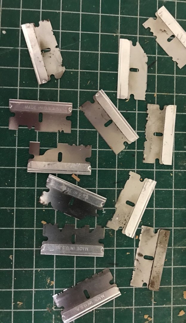
Druxey I have tried using hacksaw blades as well and they work just as well as the razor blades regarding stiffness, in my experience. One advantage I have found with the razors is they are thinner and do not have to be heat treated and softened before grinding the shape. Both give excellent results as long as easy strokes on the wood are used at the start rather than trying to dig in and give the shape with one or two passes. Mark, I usually use my lathe, chucking the grinding wheel and resting the blade on the tool holder then manually moving it to the shape I want. I like to start by marking the shape as close as possible with a fine tip marker or better, coating it with Dykem Steel Blue layout fluid then scribing the shape into the blue so there is an accurate drawing to follow for the grinding. I have also clamped the Dremel in a vise and then use a block of wood or some such on which I rest the blade while I move it in and out. GO SLOW, as the thin disks will break very quickly if forced to work faster than they are meant to. AND WEAR SAFETY GLASSES OR GOGGLES!! If the grinding wheel breaks, bits fly all over the place. Allan
-
One other way to make moldings/rails scrapers. I like to use stiff backed razors, shaped as mentioned above with thin grinding wheels set up on my lathe or can be done with a Dremel or similar rotary tool. I make them as needed and save them for future use. I never found a problem with any shape or size. If small, several shapes can be cut into one blade. Allan
-
Thanks for sharing Joe and Druxey. A key point, IMHO, is that Druxey mentions use of white glue. It works perfectly and does not leave a hard and brittle finish which CA, as Joe shows, will do. Both methods look really good to me, just not a fan of super glue, especially on rigging. Thanks again to both of you. Allan
-
Hi Caroline Assuming you are building the 16 gun sloop of Pegasus 1776, according to what I can find in W.E. May's Boats of War, she would have carried a 19 foot longboat and 26 foot pinnace, although in 1777, 16's of more than 300 tons were given an extra 18 foot four oared cutter. Does this sound right for your model? Please keep in mind that you cannot necessarily just change the scale of a drawing to the size that you need without making alterations. For example, if the drawing you use is a 28 foot 16 oared longboat, when scaling to a 19 foot long boat, the number or size of the benches. number of oars, and other parts are not necessarily to be scaled. Even the shape is likely to be wrong when just scaling as the proportions of breadth to length vary for shorter or longer boats. For example, the proportion of length to breadth of a 32 long boat of about 1800 is 3.36 while for a 19 foot long boat the proportion is only 2.68. They are similar but slightly larger proportions given in Mays for 1745 as well, 3.45 for a 32' long boat for example. Cheers Allan
-
Pantograph to enlarge plans
allanyed replied to Sambini's topic in Modeling tools and Workshop Equipment
I add a scale to drawings that I print at home or at FedEx, Staples or architectural service places. If my own CAD drawings I take the drawings on a flash drive. I check the first print with a they make with caliper to be sure the scale on the printed copy is EXACT (6") . If it not, they can adjust accordingly. Once adjusted, the following prints on that machine at that time will be exactly right. The same can be done if you give them a small drawing that you want enlarged. If the small drawing has a scale of say 5", and the enlargement is 4X, the scale should be 20" I have seen the first copy be off as much as an 1/8" or more so it is good to check. They never charged me for their mistakes and happy to make the adjustment. $30?? For drawings from a flash drive, Staples charges $1.80 for Arch C (18X24"), $3.60 for Arch D (24X36") and $7.30 for Arch E (36X48) in black and white. Color is $3, $6, and $12 for the same three sizes. Not sure on enlarging copies from an existing paper drawing, but I think they are similar in price. Allan

