allanyed
-
Posts
8,149 -
Joined
-
Last visited
Content Type
Profiles
Forums
Gallery
Events
Everything posted by allanyed
-

How are sails fixed to yards?
allanyed replied to Louie da fly's topic in Masting, rigging and sails
The following may help. Note that the reef knots indicated are in fact square knots. Allan.thumb.jpg.c59c769384ab87a1caa0754d0590da34.jpg)
-
My all time favorite for planking ships' boats is holly. When wet it is extremely flexible for bending into frames over a forming plug and works very well dry for the planking. If the boats were painted white, the wood itself will negate the need to add paint. For other pieces European box or Costello Box are both great. Just one more opinion..... Allan
-
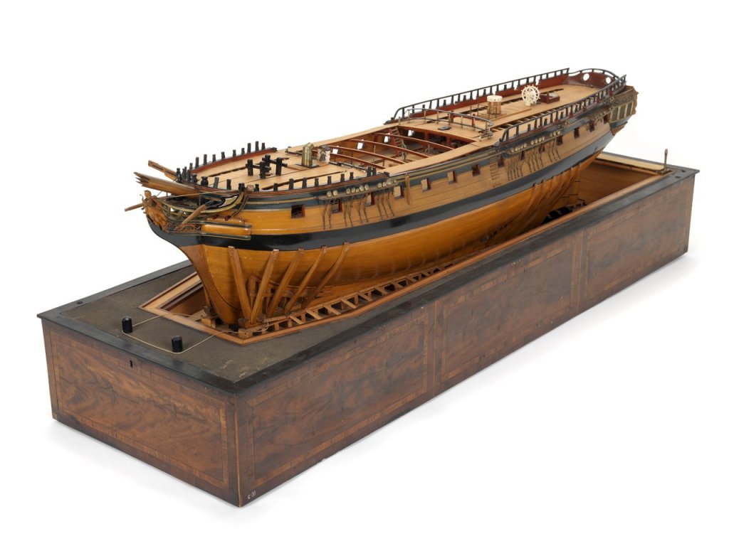
Greenstone Wreaths (on English ships at least) were no longer used on new ships built from about 1703 so this ship is likely 17th century. The carvings are more ornate than would be found on ships built in the 18th century. Do you have the name of the ship in the photos? Allan
-
Based on photos and plans that I could find that are appropriate to French ships in the 18th century, I believe the outboard rail would be a series of permanent U-shaped stanchions called hammock cranes in which hammocks would be stowed after being rolled and passed through a measuring ring when not in use. They would be walled in with canvas or netting. Per a description from Goodwin, the English first secured the cranes with a single spike into the plank sheer but then later followed the French practice of having the bulwarks partially built up and cranes were secured to the inboard side of the bulwark rather on than on top of the plank sheer. There would be no rail at all around the waist. The inboard rail on the replica is indeed more likely to prevent lawsuits due to not following modern safety practices. The ship's boats would be hoisted over these hammock stowage rails so there was no need to make them flexible or removable. Allan
-
Jeffrey This may be an easy way out, and specific to one or two vessels. Zephyr 1779 (14 gun brig) drawing https://collections.rmg.co.uk/collections/objects/85176.html If you download and print the drawing you can measure the angle pretty accurately for that brig. You can compare it to Swift (8 gun brig sloop), 1783 as well. https://collections.rmg.co.uk/collections/objects/84645.html Allan
-
Preprinted lines
allanyed replied to achuck49's topic in Building, Framing, Planking and plating a ships hull and deck
Chuck If you don't have a drawing program that you are comfortable using but you can scan the image, PM me and I maybe I can do this for you. If you prefer, the easiest thing to do is as Druxey describes. Allan -
source for steel bar stock?
allanyed replied to Griphos's topic in Modeling tools and Workshop Equipment
Try McMaster Carr https://www.mcmaster.com/steel-bars Allan -
Holding small parts for soldering
allanyed replied to BETAQDAVE's topic in Metal Work, Soldering and Metal Fittings
I assume you are silver soldering so an iron would not work, I have a block of material made for soldering at most any temperature. It is soft enough to dig into it which I have done on numerous occasions to hold a piece in place. Hard to describe in words so if my explanation is unclear, I can try to post a photo or two to give you an idea of what has worked for me. Using a wire to hold things in place does work but you would need to make sure it cannot be heated to the same temperature. Clip on an alligator clip on the piece not to be soldered and it will draw away enough heat to keep the hold down piece from being soldered. If it is still a problem, clip to the wire that is not to be soldered with a wet piece of cloth or tissue in the alligator clip as well. Allan -
Pieter, My misunderstanding. I thought you were referring to the sheer , cap, counter and other rails on the sides of the ship, not at the stair openings. Cheers Allan
-
Pieter The short answer is I do not think there were any brass railings on any ship of the line in the 18th century. These would all be wood, and most likely painted or other wise protected. If you choose to go with wood they are easy to make with home made cutters made from pieces of an old hacksaw blade or stiff back single edge razor. That said, if you choose to use the brass in the kit, I imagine they can be painted any color you feel is appropriate, be it black, a wood tone, or left alone as you mention. Allan
-
Paul I may be way off base here, but I don't think there are supposed to be gun ports cut into the bulkhead for the chase guns. Photos of Artois class ships, including Diana, at the NMM Collections site do not have ports for these guns. The photo below is from NMM for Diana http://collections.rmg.co.uk/collections/objects/66533.html Allan
-
If you cannot make a master yourself, maybe just buy one of each size then make a mold and cast your own as suggested above. The cost of making a silicone mold then casting with resin or pewter or similar lead free metal will be less than buying all of them. There was a recent post on casting barrels here, so could give you an idea on what is involved if want to go in that direction. If you do buy a single barrel for each size, be sure they are to scale for your needs and contemporary in design as there were differences over the years in both long guns and differences in carronades, albeit smaller differences. Good luck Allan
-
Miniature Russian carving tools
allanyed replied to druxey's topic in Modeling tools and Workshop Equipment
I realize this string is over a year old now, but as I just ordered a set of chisels from Mihail that he is targeting to ship early February I would like any information on sharpening based on members' experience that have used his or similar sized micro chisels. I use the Veritas for relatively larger chisels but gather from earlier posts that this does not work for the micro chisels. I am envisioning a triangular block with various angles of 25 degrees, et al to hold the chisel at the proper angle when honing on a stone and then stropping but this seems almost too simple. In addition, I have a small leather stropping pad and stropping compound, but if there are suggestions on a better stropping device, I am all ears. Allan -
Hi Bill You can download the thesis on slavers by Jessica Glickman and there is a lot of information, including a large bibliography that might lead you to appropriate plans of a slaver. https://digitalcommons.uri.edu/cgi/viewcontent.cgi?referer=&httpsredir=1&article=1668&context=theses Allan
-
Paul, You may be correct in that there may have been a few fingers on the deck, but keep in mind these sails were not used except with lighter winds, or as Harland describes in Seameanship in the Age of Sail, in reasonable conditions. In these conditions, when the wind was near abeam, the weather side studdingsails might come out. The lee side would not be used unless the wind was about dead aft. Keep in mind, the topsail yard studding sails and even the topgallant yard studding sails saw more use than the lower yard studding sails. Regarding the lower yards, the foreyard studding sails were used far more than the those on the main yard. The main lower studdingsails fell out of use completely after about 1800. There was a lot of rigging involved with the sails themselves and described in great detail on how they were rigged and used in Harland's book for anyone interested. Allan
-
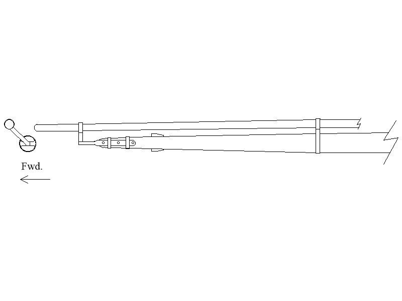
Hi Antonio Your photo appears to the booms tied to the spar with line instead of mounted with iron rings. What ship/year/nation is your model? The mounting varied with nation and era, but I do not believe they were ever tied with rope of any kind. For example for British ships that carried stunsail booms there were two boom irons on each side of the yard. For British ships the rings through which the booms passed lean forward 45 degrees up to 1850 then they were at 22.5 degrees. They do not sit straight up on the spar nor do they lay in a flat plane as you show in your photo. The outboard ring through which the boom passes had a roller in them after 1773. The inner ring through which the boom passes was hinged after 1773. Dutch ships carried the booms abaft the yards. The outer rings were fitted with straps and bolts to the end of the yard and the inner rings were about 1/3 of the length of the boom in from the end of the yard. Hope this helps. Lees shows some very detailed drawings of the boom irons. Allan
-
Further to the comments above, many of the bowlines would have had bridles, with two to four ropes hitched to the yards depending on the era, size of the ship and yard, when no sails are rigged. Allan
-
Looking at contemporary model photos, there seems to be no end to the shapes on each model, but Ed's tutorial should work well for any of them, just be careful whether your ship's blocks would have had rope strops or metal as on the more "modern" clipper. I saw a video or series of photos quite a while ago that showed shaped cutting bits used on a mill to cut the outside shape so every block was shaped the same. Each size block had a different cutter, but they were beautifully done. Barring the above, I would go with Chuck's blocks. Allan
-
Antonio FWIW the sling cleats in the center don't look quite right and I doubt very much that there would be the partial ring shown on the kit yard to attach to the mast. The yards would likely use parrels and or some type of sling. The cleats at the end of the yard should hold up well with just gluing them on with carpenter's glue, no need to make a slot. There are Connie experts on this forum and can probably share more details with you. Be sure to rig the various buntline blocks, lift blocks, brace pendants, etc. to the yard before putting the yards to the masts. It is much easier to seize these to the yards while off the model. Good luck on your build!! Allan
-
Ed There are probably several good sources, but Lees Masting and Rigging is a great source to get into the details down to attaching buntlines, leech lines, bowlines &c. to the sails themselves as well as the rigging from the sails to their belaying points. Allan
-
I am awed at your work Doris. This may have been asked before, so apologies if this is a repeat question. Do you have any problems with the wax paper melting in the oven? I did little reading on this subject and have seen recommendations to use parchment paper in place of wax paper. Thank you for sharing your work with us. Allan
- 1,035 replies
-
- 7
-

-
- royal katherine
- ship of the line
- (and 1 more)
-
Thank you Dave and Henry Henry, I was actually looking for the belaying point of the fore topsail buntlines not the bowlines. I did have the same description for the bowlines that you gave from several sources, so we are in agreement, thank you very much for your reply. The fore topsail buntlines appear to belay to the main topsail bowline bitts and that was my dilemma, finding where these bitts were located. Dave you pegged it, I found them on the one drawing in Lees and it is shown as you described it. My fault for not searching a "bitt" harder. Thanks again Allan
-
This is probably an easy one for someone out there, but I have not been able to find where the main top bowline bitts are located. These are referenced in various sources as a belaying point for the main topsail buntlines, but I cannot find a drawing that shows where these are actually located. Thank you for any help that can be provided. Allan
-
Clewline attachment to Topsail yard,HMS Cheerful
allanyed replied to davyboy's topic in Masting, rigging and sails
Hi Anderson also states that the clew is secured to the yard with a timber hitch so it appears this was the method from the 17th century to the 19th century. Allan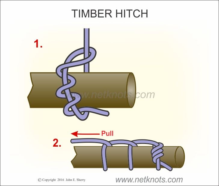
-
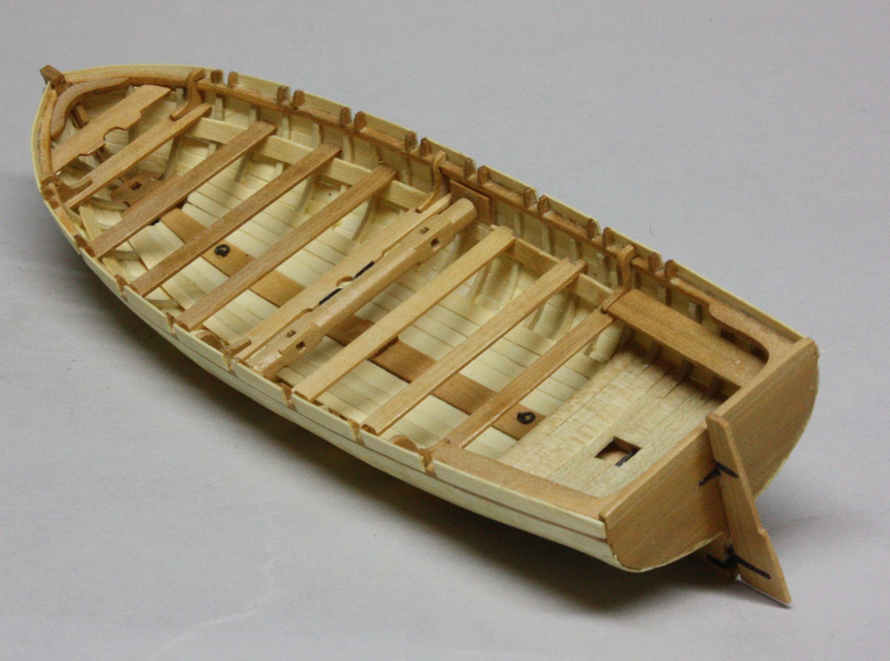
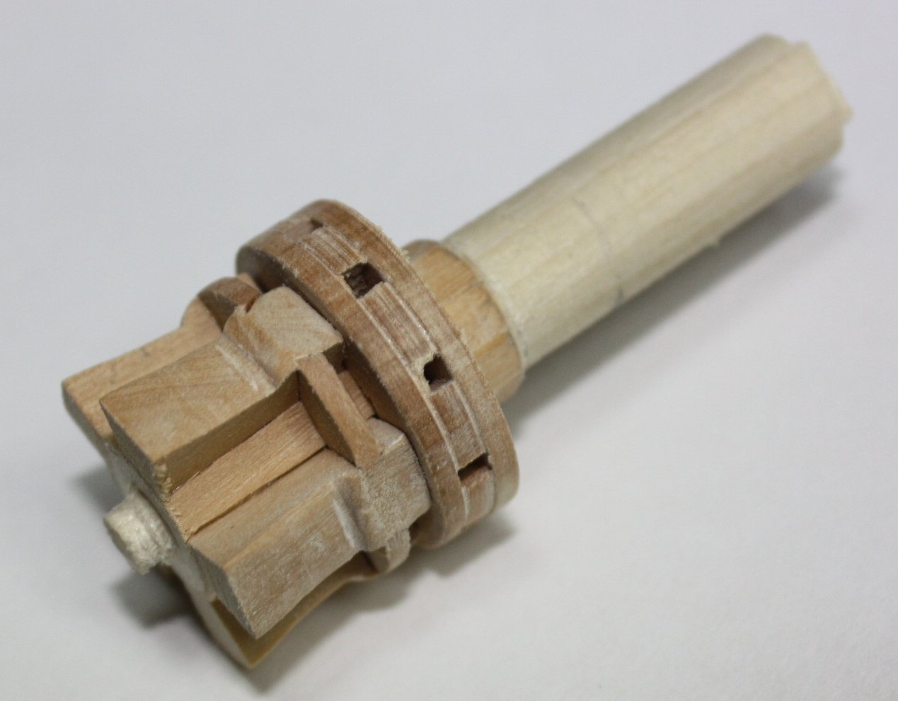
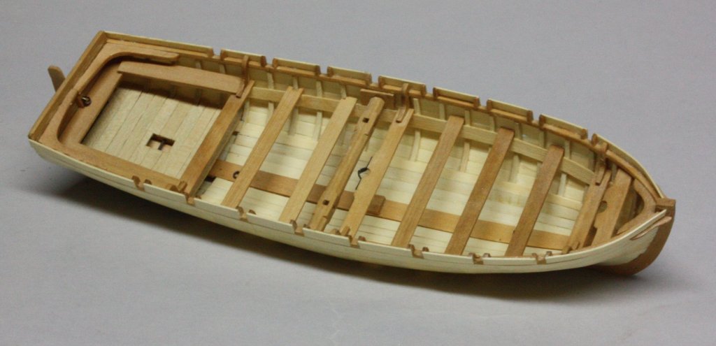
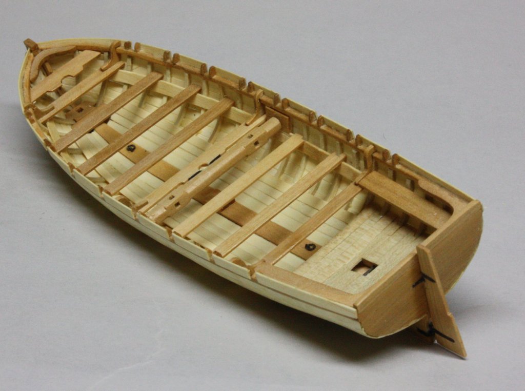
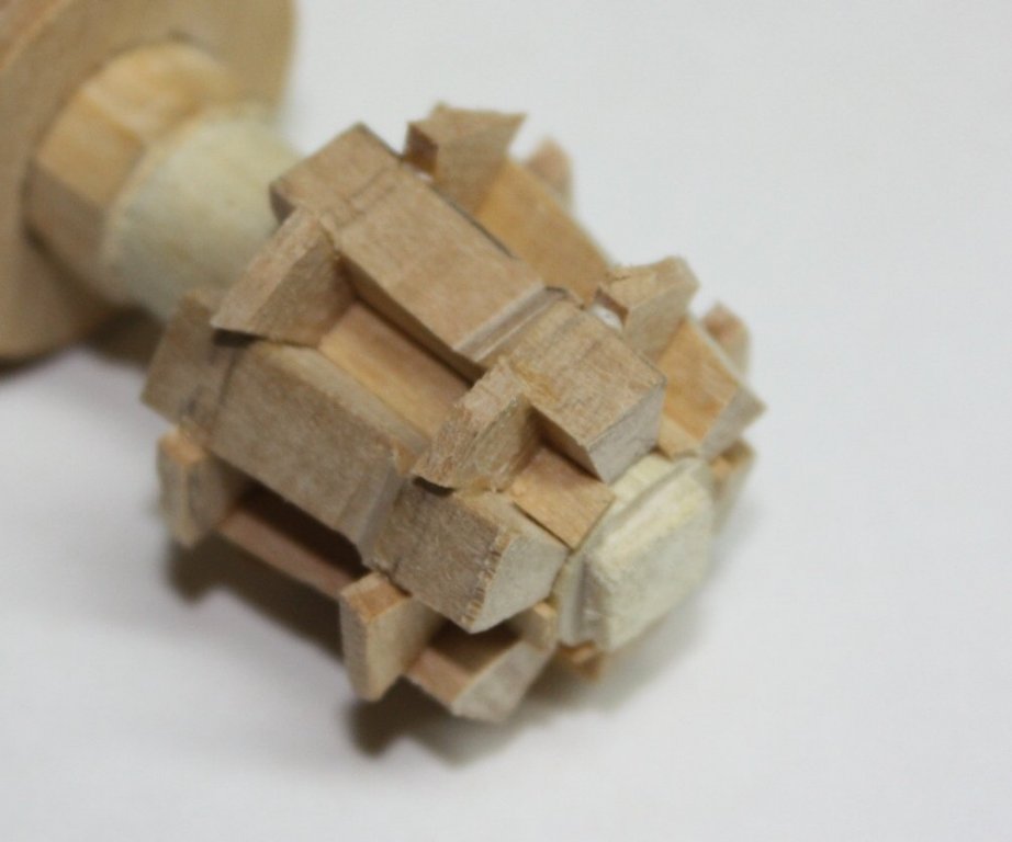
A bit late for you to try this Art, but another way to skin a cat...…. Assemble, then finish with your lathe. Pictures are easier to see what I mean.

- 1 reply
-
- 4
-
.jpg.bc34a0ef5515d5448db015ac6dabefe6.jpg)