allanyed
-
Posts
8,149 -
Joined
-
Last visited
Content Type
Profiles
Forums
Gallery
Events
Everything posted by allanyed
-
 Don't know what to say except it does not look right at all. Look at the rope from Syren below to see what I mean. Not to say you have to get rope from Syren as there are other sources or you can make your own if have or can build a small rope walk, but what you show could distract from the rest of your model. Maybe check with other Aussie members to see what they have used. Allan
 -
‘Eighteenth Century Rigs & Rigging’ by Marquardt
allanyed replied to bruce d's topic in Masting, rigging and sails
Bruce For English Men of War books that covers a lot of details both Lees' Masting and Rigging and Anderson's Rigging of ships are hard to beat for details including block and line size, run of the lines etc. Allan -
Pin vice recommendations?
allanyed replied to CPDDET's topic in Modeling tools and Workshop Equipment
Dave, For bitts for wood, the set Bob shows are great. But, if you are going to be drilling through brass or even steel, they will not hold up very long. McMaster Carr has bits in wire gage sizes down to 96 if I remember correctly. They are a "bit" pricy but will not dull for a long time. They have steel, carbide and other materials, but the prices do get ridiculous for the super high end bitts which are probably never needed with the materials we use in this hobby of ours. You really do need a very good pin vice to hold the tiniest bitts securely. Allan -
Pin vice recommendations?
allanyed replied to CPDDET's topic in Modeling tools and Workshop Equipment
My dentist gave me a few used burrs and I found they were far too dull after grinding tooth enamel when the smoke started rising from the wood on which I tried them. He then gave me a few new ones and they were much better, but the range of sizes was small so I bit the bullet and bought a variety of cutter and polishing burrs with different sizes and shapes. I am now trying a combination of burr carving for the initial shaping work, and chisels and gouges for the detail work and texturing. Allan -
The only way to do a good job is remove the sails and wash them then re-rig them. There are a number of recipes for washing cloth with nicotine stains on the 'net. Is this a decorator model or a model his dad built himself? May not be worth the effort if a mass produced decorator model although it is impossible to put a value on sentiment. Allan
-
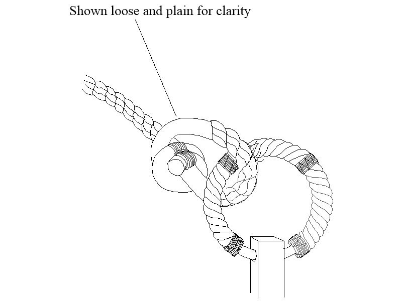
John I admire your work very much. One comment, hope you don't mind, the anchor cable would not be knotted and seized as you show but rather would be tied to the anchor ring with a knot similar to that below while in use.
-
These look REALLY well done. I have always been a proponent of silver solder, but you have given me pause after seeing your use of low temp solder and now epoxy for the last tongue/extension piece. Well done. Allan
-
Ferit What ship and year and which yards? These are actually not reinforcements, but rather are stunsail booms and were attached to the yards with stunsail boom irons in such a way that they were separated from the yard itself by a few inches. The configuration varied (at least on English vessels) over time and were different for the lower yards than the upper yards. There are four stunsail boom irons on each yard that carried these, one near each end of the yard and the others 1/3 of the length of the stunsail booms in from the ends. The booms then could slide outboard when in use with the stunsails, and inboard when the stunsails were not deployed. Lees gives a good amount of detail on these in The Masting and Rigging of English Ships of War Allan
-
She is looking super Phil! One comment in general on sail material. It is VERY difficult to find cloth material that does not look out of scale, but a good alternative is either silk span as it is non-woven material, or if one wishes to use actual cloth, high thread count (1000 or more) Egyptian cotton. To keep the cost down, one package of pillow cases will be enough to make a lot of sails. The boss here says there is something wrong when I use higher priced cloth for models than we have on the beds!! Seams can be drawn on with a very sharply pointed mechanical clutch pencil with a hard lead to avoid sewing seams when they are too large in scale. Volume 4 of TFFM has a wealth of information on this subject. Allan
- 355 replies
-
- 3
-

-
- prince de neufchatel
- schooner
- (and 3 more)
-
I found the following quite interesting and thought some of the members would as well. https://aeon.co/essays/how-european-sailors-learned-celestial-navigation It follows: In 1673, in a North Sea skirmish that killed nearly 150 men, the French privateer Jean-François Doublet took a bullet that tossed him from the forecastle and broke his arm in two places. How did the precocious young second lieutenant choose to spend his convalescence? Doublet repaired to the French port city of Dieppe, where he signed up for three months of navigation lessons. This might seem a strange decision; Doublet, who had gone to sea at the age of seven, already knew the ins and outs of navigation. Why would he bother paying for lessons? The school in Dieppe – the Royal School of Hydrography – was renowned for the calibre of its lectures, attracting passing tourists as well as naval trainees. Doublet was keen to learn some more advanced techniques from the teacher, Abbé Guillaume Denys. In his memoir, Doublet explains a practical motive too: if he got injured again, he would retire and open his own sailing school. Bold adventurers had a chance to enjoy considerable profits at sea in the early modern period (the 16th to 18th centuries) but they also risked their lives on every voyage. For Doublet, it was important to have a backup career plan. He never ended up teaching – he would spend the next three decades traversing the Atlantic and hobnobbing with famous admirals before, as a retirement project, writing his memoir. It might seem surprising that Doublet felt that teaching navigation was on a par with privateering, which was essentially legal piracy, with handsome prize money. Clearly, in the late-17th century, even knowledgeable sailors sought out more education. Records of these early schools are scarce – but Doublet’s detailed account of his time in Denys’s classes offers a rare glimpse into the technical education that early modern European sailors might have received During the 16th to 18th centuries, Europeans embarked on thousands of long-distance sea voyages around the world. These expeditions in the name of trade and colonisation had irreversible, often deadly, impacts on peoples around the globe. Heedless of those consequences, Europeans focused primarily on devising new techniques to make their voyages safer and faster. They could no longer sail along the coasts, taking their directional cues from prominent landmarks (as had been common in the preceding centuries). Nor did they have sophisticated knowledge of waves and currents, as did their counterparts in the Pacific. They had no choice but to figure out new methods of navigating across the open water. Instead of memorising the shoreline, they looked to the heavens, calculating time and position from the sun and the stars. Celestial navigation was certainly feasible, but it required real technical skills as well as fairly advanced mathematics. Sailors needed to calculate the angle of a star’s elevation using a cross-staff or quadrant. They needed to track the direction of their ship’s course relative to magnetic north. Trigonometry and logarithms offered the best way to make these essential measurements: for these, a sailor needed to be adept at using dense numerical tables. All of a sudden, a navigator’s main skill wasn’t his memory – it was his mathematical ability. To help the average sailor with these technical computations, maritime administrators and entrepreneurs opened schools in capital cities and port towns across Europe. Some were less formal arrangements, where small groups of men gathered in the teacher’s home, paying for a series of classes over the course of a winter when they were on shore. Illustration of a small Dutch classroom from The Golden Light of Navigation (1697), by C H Gietermaker. Courtesy Rijksmuseum, Amsterdam In other instances, the crown set up official schools, usually footing the bill for young men who were expected to then serve in the nation’s navy. Many of these were modelled after the first official school, established by the Spanish crown in 1552 at the House of Trade (Casa de la Contratación) in Seville. It was counterintuitive to teach sailors in classrooms – most were barely literate – but educators chose to follow the pattern set by traditional universities: lectures, note-taking and formal examinations. Administrators devised ambitious, theory-heavy curricula, but they provided no instructions about how to teach this material. In the 17th century, navies and trading companies began requiring their mariners to pass an examination if they wished to be promoted – to master, lieutenant, eventually even to captain. While sailors who were already competent navigators might not see the point of sitting through classes dedicated to theory, they were motivated by the prospect of upward career mobility. If you could read and had a head for numbers, you could climb the ladder quickly. A master or navigator (pilote in French, piloto in Spanish, stuurluy in Dutch) earned three times as much as an able seaman, and many would eventually secure commissions as captains. Sailors flocked to the classroom. Sailors needed to learn the terms that would have been familiar to university students studying cosmography The first schools in northwestern Europe popped up near the docks in Amsterdam, Le Havre and London. They were run by ambitious entrepreneurs who wore multiple hats: a number of them invented new instruments or wrote introductory textbooks, all of which they hoped to sell to their students. Some were mariners themselves, but most had virtually no experience at sea. Still, they harnessed the power of the printing press, and instruments galore, to help teach new mathematical concepts. One teacher in Rotterdam, Jan van den Broucke, published a small textbook, Instruction about Navigation (1609). The humble volume was illustrated with the latest paper tools: tables, diagrams and moveable instruments. Van den Broucke offered keen sailors practical advice about how to get up to speed on astronomy. He reviewed basic definitions: what is a pole? Where is the equator? Sailors needed to learn the terms that would have been familiar to university students studying cosmography (the celestial parallel to geography). The Instruction included a list of 12 key concepts – from the signs of the zodiac to charts and compasses. Van den Broucke advised his readers to ‘hang the list over their bed [and] review it every evening for a year’. If they found such memorisation onerous, they could come take classes with him instead. Van den Broucke taught readers and students a useful technique: how to use the Little Dipper to tell time. The handle of the dipper points at the North Star, and the bowl of the dipper rotates around it over the course of 24 hours. That means that when the two farthest ‘guard stars’ moved 15 degrees, one hour has passed. Once the constellation has rotated 90 degrees, six hours have passed. This functionality was so useful that most early textbooks included diagrams, often with volvelles, moveable discs that help the reader understand the concept. A Volvelle (Dipper) from Instruction about Navigation (1609), by Jan van den Broucke. Courtesy Leiden University Library Van den Broucke’s Instruction also offered a more elaborate tool for mastering the heavens: the ‘zodiac song’. To help students remember the stars, the song rendered all the constellations in 12 rhyming verses. In the northern hemisphere in March, for instance, you first see Andromeda’s belt rising in the sky, pursued by Cetus the Whale, followed by the ear of Aries the ram. These verses were set to the tunes of familiar hymns. Devout sailors could sing along, or so seemed to be the intention. It is doubtful, however, that many sailors learned the constellations through music. Claas Gietermaker, author of the immensely successful nautical manual Golden Light of Navigation (1660), included two different songs in the first edition of his Dutch textbook. But Gietermaker left the songs out of subsequent printings. He did retain two volvelles, suggesting that sailors found the hands-on spinning discs more useful than the verse and tunes. By the time Gietermaker published the Golden Light of Navigation half a century after Van den Broucke’s Instruction, nautical manuals had evolved. The definitions that had been so important – pole and equator, zenith and meridian – had become common knowledge, and sailors now focused on a different set of essential skills: addition and subtraction, multiplication and division. The volumes burst with the newest tables and equations. Teachers took their students outside to make observations along the shoreline. Other classes piled into small boats so that they could sketch the coastline, training their eye for estimating distance as well as for cartography. At larger institutions, pupils might get to practise working the rigging of real or model ships. More often, a small group of men would gather around a table with a blank workbook, a set of drawing compasses and a globe. Teachers usually had all of this equipment available for purchase (and might even rent out a storage drawer for a small fee). The Kaatje training ship in the courtyard of Amsterdam’s Seminary for Navigation. Courtesy Rijksmuseum Classroom activities involved a fair amount of rote memorisation, and students were expected to copy out their teachers’ lectures verbatim. By the 18th century, teachers petitioned central administrators to ask that the students not waste time by copying out the textbooks – let them simply buy a copy! Students owned manuscript workbooks where they copied out definitions of key concepts and answered questions. Some mariners spent more time on decorating their notebooks with calligraphy or doodles than on mathematics. But the manuscripts are invaluable: they let historians track which topics received the most attention, where students made the most mistakes, and what they did each day in class. ‘What course shall the man of warre shape to finde these pyrates?’ The most important textbook questions had to do with the boat’s course and position: ‘If your ship intends to sail west but is forced off-course by the wind … what is your true course and distance sailed?’ Straightforward trigonometry could give the answer. But sometimes a teacher would put more spin on the problem. Richard Norwood, in his Trigonometrie (1631), presented the following scenario: What is the next step? Naturally to hunt down the pirates! Since the merchant had ‘sailed since at least 64 leagues betweene the south and west, what course shall the man of warre shape to finde these pyrates?’ For more than a century, variants on this ‘pirate question’ appeared in textbooks. There were also more idiosyncratic problems: one Dutch student carefully drew a trapezoid to answer a question about four old ladies sewing – how far apart were they from each other, and how many yards of cloth did each stitch? One common classroom exercise required students to trace out hypothetical routes for vessels as they zigzagged through a day’s sail. To make this interesting, teachers designed fantastic courses – castles, anchors, hearts – that students constructed in their notebooks, connect-the-dots style. From the navigation workbook of William Spink RN (c1697-1731). Courtesy National Maritime Museum, Greenwich, London Such questions aimed to make technical material as memorable as possible. Textbook publishers, for their part, did not want to dedicate costly paper to these sizeable diagrams – they appear almost exclusively in manuscript workbooks. Here again, the discrepancy between published book and student work tells us which parts of the extensive curricula were truly important. These classroom records reveal the theoretical material that sailors actually used at sea. Thanks to the French privateer Doublet, we can get insight into the 17th-century ‘student experience’. We know from Denys’s own correspondence that he had been running a navigation school in his home since the 1650s. When Louis XIV’s main advisor Jean-Baptiste Colbert asked him to convert it to a royal college, Denys sunk money into renovations, for which he was never properly compensated. (Teachers, always underpaid, lodged many such complaints. They often supplemented their income with private tutoring on the side, but this could cause problems; their favourite students never failed the exams.) Denys’s school was on a noisy corner; he reported that it could be hard for the students to concentrate over the din of women selling their wares. Denys grumbled to Colbert about his feud with the merchant who sold the only magnets in town, obviously an important piece of equipment for mariners. Despite these issues, Denys’s hundreds of students evidently loved him, and he stood as godfather for several of their children. Doublet tells us about Denys’s school itself. In 1673, he paid 50 livres a month for room, board, laundry and the necessary books. (These were almost certainly Denys’s own pioneering textbooks, which introduced trigonometry to French sailors.) Doublet notes that most students started with the basics – the tides, altitudes, and simple instruments such as Gunter’s scale and the sinical quadrant – but Doublet easily worked his way through spherical trigonometry and Euclid’s Elements. The young corsair turned out to be so proficient at the advanced mathematics of celestial navigation that Denys offered to foot the bill to keep him on in Dieppe as a teaching assistant. ‘You would oblige me infinitely by staying, for you would ease the puzzle of this [large] number of students, the majority of whom have heads as hard as stone.’ Denys made typical complaints about students. If some were bright and diligent, others stole school supplies or sold their textbooks for a profit. Absenteeism was a problem. French administrators experimented with paying senior naval officers to attend classes as role models – but that did not stop them from playing hooky. The navy then docked the wages of men who didn’t show up for class. At a Dutch school for officers in Batavia, the best student in class earned a sword. Doublet needed no such coaxing. When his squadron leader ordered him back to sea after three months, Denys pushed back so that Doublet could stay in the classroom for three months more. Doublet was thrilled: he scored ‘six months of room and board for which I only paid three’. After this stimulating scholarly interlude, the Franco-Dutch war (1672-78) continued to intensify so Doublet hurried back to sea to harry the enemy. But first, he did something that was increasingly obligatory for sailors: he took his navigator’s exam. (Denys covered the cost.) As was the custom, Doublet stood in front of a panel of ‘Four old captains and four pilots, who questioned me from all sides.’ The bright young corsair passed with flying colours. After a celebratory feast with Denys and his sister, Doublet finally headed back to his squadron. Captain Dering, an overconfident young Brit, failed to correctly calculate the time of high tide at London Bridge If Denys was unusually gifted at Euclidean geometry, many other average mariners followed him into the classroom to face the examiners. By the 18th century, sailors spent some portion of their training in a schoolroom. Navigation was no longer an art learned by apprenticeship – it was a science. Textbooks poured off the presses; sailors filled their workbooks with trigonometry. Although exams might not have been mandatory in every locale, mariners were keen to pass them. The Dutch author Gietermaker included a model exam paper in his Golden Light of Navigation. This simple two-page innovation made waves. Other authors quickly copied Gietermaker, and before long, most Dutch textbooks included a practice test. Soon after this, mariners started cramming for exams. Instead of paying 36 florins for an entire winter of lessons, Amsterdam-based mariners paid just 6 florins for a crash course focused on the oral and written portions of the tests. Later manuscript workbooks confirm this strategy: students often focused on the questions they knew would be on their exam. Teachers at the close of the 17th century were already ‘teaching to the test’. What were these exams like? Evidence is sparse, and Doublet is regrettably silent on his own experience. Admiralty records do preserve records of those who ran into difficulty: men who desperately wanted to earn their certificate, but repeatedly failed their examinations. Some flunked due to seemingly minor errors, while others persisted, and eventually earned their credential. For instance, Captain Dering, an overconfident young Brit who had ‘pretended to be a lieutenant after having been [on] one voyage to Wyborne’, failed to correctly calculate the time of high tide at London Bridge. This was one of the most straightforward and essential tasks – so he was summarily sent back to his ship, and told to reapply at a later date. A practice exam in the navigation workbook of C. J. Boombaar (1727–32). Courtesy Het Scheepvaartmuseum, Amsterdam. In the 1760s, a Dutchman, Frans van Ewijk, already held a position as a merchant captain. Unfortunately for him, the Dutch East India Company passed a rule making exams mandatory even for captains. In October 1768, Van Ewijk presented himself in Rotterdam for the exam – and promptly failed. He was deemed ‘very deficient in theory and practice’, and unqualified to serve as captain. He blamed his servants for distracting him with ‘much confusion and trouble’ at home, but the committee was not sympathetic. Undaunted, Van Ewijk showed up at an exam room in Amsterdam six weeks later. This time, he answered the questions satisfactorily. (Perhaps he had taken a crash course?) The following summer, Van Ewijk once again sailed as captain of a ship. Another English candidate, Charles Hadsell, wished to get certified as a ship’s master in 1670. Just returned from the Caribbean, he had sailed for a decade with the notorious Captain Henry Morgan. In spite of more than 10 years at sea, he failed the master’s exam – twice! The panel of naval examiners found that ‘he could not give any Considerable answere to moderate questions in Navigation’. Even if he knew every cove and reef in the West Indies, they were clear: ‘We doubt of his Capacity in navigating a shipp on the greate Ocean.’ We cannot know if the Admiralty disliked Hadsell because he’d associated with the notorious pirate, but it seems clear: to please the examiners, he should have studied some practice questions. These mariners needed more than vessel-handling skills – definitions and theoretical concepts demonstrated your expertise to those around you. In their quest for these credentials, maritime men sought out formal schooling. Pirates, privateers, merchants and navy hands did not just sail a boat from point A to point B; they needed to be able to track its position, to compute time and place. To do this, they needed mathematics. Fortunately, in the 17th and 18th centuries, practical mathematics took off. For a reasonable fee, anyone who wished could acquire this bookish knowledge. Europeans felt the stakes were high, for their colonial fortunes rested on the shoulders of these navigators. In response, maritime educators developed an innovative hybrid form of training. Early modern navigation students memorised definitions and took notes but also got their hands on instruments, and answered many, many practice questions. Zodiac songs, creative diagrams, hands-on lessons along the beach – this combination of memory and mathematics caught the imagination of mariners, making it easier to grasp the technical skills needed on the high seas. Far from being drunken sailors, these men were clever mathematicians, using traditional approaches alongside the latest technologies to reach the far side of the globe.
- 1 reply
-
- 10
-
-
Tim The timing of the introduction of the steering wheel in place of the whipstaff is conjectural and Brian Lavery goes into it in some detail on pages 18 and 19 of The Arming and Fitting of English Ships of War. While he could not find a specific date with an official edict to use a wheel versus whipstaff, there are models circa 1703 with a windlass and another with a single conventional wheel design. On the other hand there is a model at NMM of the Gloucester 50, 1711 with a whipstaff companion. Lavery states that the use of a wheel spread fairly rapidly after 1711, and it seems to have been a standard fitting on warships by 1715. Antelope would likely have had a whipstaff in 1703. There were roundhouses (poop decks) in use long after the introduction of the wheel for steering. Scantlings for the roundhouse are given in both the 1719 Establishment and 1745 Establishment. The rounding for the roundhouse deck beams is given as 8" in 1719 and 8.5" in 1745. Further, scantlings in Steel's Elements and Practice of Naval Architecture 1805 are given for roundhouses of ships of 50 guns and larger with a rounding of 8.5". With the Golden Age of Piracy going from the mid 17th century to about 1730, there were a lot of design changes in the British navy and presumably in the navies of other nations. Good luck in your project! Allan
-
Jaager, thanks for the plug on the Scantlings book, much appreciated. Tim, the 1719 establishment scantlings will be close to the scantlings earlier in the 18th century but not exact. Also, there are some transitions to consider in the look of the vessels at that time. To address your question, interior and exterior wise there are differences in appearance between 1719 Establishment designs and pre-1719 Establishment designs. A couple basic examples- Wreaths were present until about 1705. Photos of some models of 1703 that I have seen have wreaths, others do not. Spritsails were still to be seen even when jib booms started to be used about 1700. The wales were split for the first years of that century, but transitioned to wider (not split) wales. There are no stern timber standards on top of the round house, but there were tabernacles or a similar block to support the stern ensign staff. Interior construction has differences as well. The shapes of capstans, cannon, etc were different in 1700 than in later years. Use of cross pillars changed about that time. Stove design was changing about that time. Swallow of 1703 would not have had cant frames. The list goes on. Your reference to cabins on quarter deck sounds like you are referring to the round house. The length on the Litchfield, 50 Gun (1695) is 9'4". The length of the roundhouse on Antelope, 50 gun, 1703 is approximately 12'. Deptford 60 gun (1732) round house was nearly to the mizen at about 30 feet long. If you are referring to the HMS Swallow of 1703, drawings and details on Antelope should be similar if not exactly the same. There are lines drawings of Antelope but no inboard profile. There are details and photos for other 130' fifties of that time that that I have found in researching my current project on Litchfield so a lot of information is out there. Hope some of this helps. Allan
-
Javelin The style you show appears to be a plank on bulk head version of models commonly known as Admiralty or Navy Board Style. These were plank on frame, albeit, not normally showing actual framing practice such as in the example of a contemporary Navy Board model from the National Maritime Museum (Royal Museums Greenwich) below. Allan
-
Sili Just a quick add on, note that Druxey mentions the "pair" of shrouds. Be sure to follow the order of dressing the masts, that is pendant of the tackles, shrouds, swifter and finally the backstay. If it is larger ship, it gets more complicated if there are standing and shifting backstays. The first pair of shrouds should be the forward starboard, at least on English ships. If there are an odd number of shrouds, the single which is a swifter will have one leg port and one leg starboard with a cut splice connecting these two to form an eye to go over the mast head. What ship are you rigging? Allan
-
Hi Jason
What is the price of the 10/4 billets of Castello? I am thinking I would like to purchase two of these if still available. Where are you in Pittsburgh? I was raised in South Hills (Baldwin High School '65) and my wife and kids were all born in Pittsburgh. We all bleed black and gold as do all of our grandkids. Thanks My email is allanyed6469@gmail.com
Allan
-
Hi Allan,
I would like to sell the boxwood for what I paid for it, which is the wholesale rate from Gilmer. $24.00/bf. I think that they are currently charging $40. I still have the whole pile sitting there. We live in Upper St. Clair, so not too far from where you grew up! I grew up in Slippery Rock, and my Wife is from Upper St. Clair.
You were the first one to contact me about the boxwood, so the first choice is yours.
Best,
Jason
-
-
Plank Bender....
allanyed replied to dvlp47's topic in Building, Framing, Planking and plating a ships hull and deck
Kriss, Each strake of planking is usually comprised of several pieces so it should be easy enough to wet the aft piece and fore piece for each strake separately. Just be sure they are kept separate, or marked, as the taper for the fore end and aft end pieces will be different. Allan -
Kevin, Does the Lavery book offer many/any detailed photos of late 17th century vessels? Thanks Allan
-
Hi Spike You would likely be much better off using the plans from Ancre which are much more accurate representations than the AL kit. For the Hermione, the Ancre plans show 6 long guns on the quarter deck, not twelve. As hinted above, if you are looking for accuracy in a kit model, AL is not a leader in that category. Allan
-
As mentioned above, the angle changes as it should be close to the angle of the frame (or bulkhead) where it meets the keel. Perhaps the below sketch will help you a bit Allan

-
Thanks Chuck! Source from you or??? Thanks again
- 1,784 replies
-
- 3
-
-
- winchelsea
- Syren Ship Model Company
- (and 1 more)
-
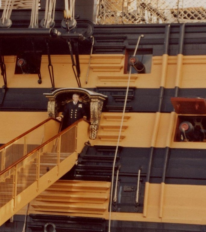
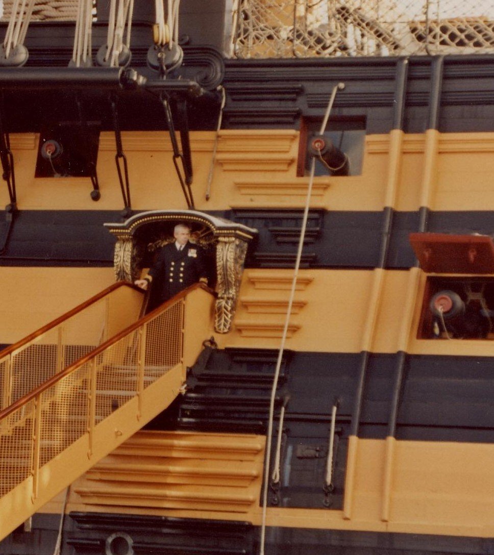
Fat old men probably were hauled up or lowered via a bosun's chair. Would not want to lose an admiral or some such. 😀 Allan
-
Chuck Are the carvings Castello box or English/European boxwood? Great work regardless, just curious. Allan
- 1,784 replies
-
- 3
-
-
- winchelsea
- Syren Ship Model Company
- (and 1 more)
-
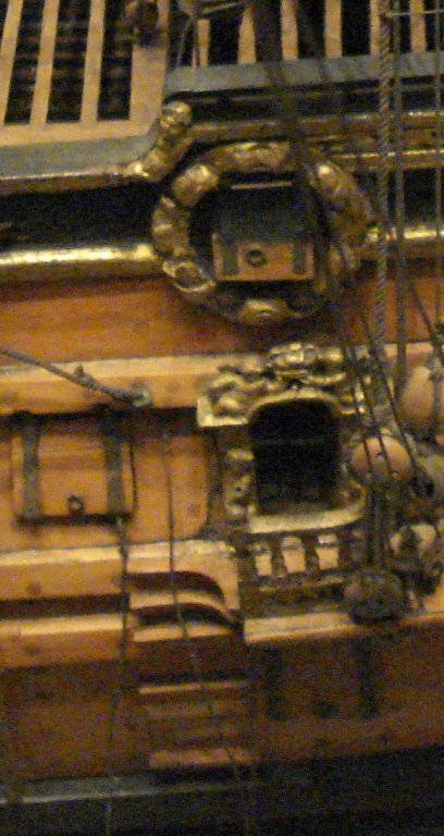
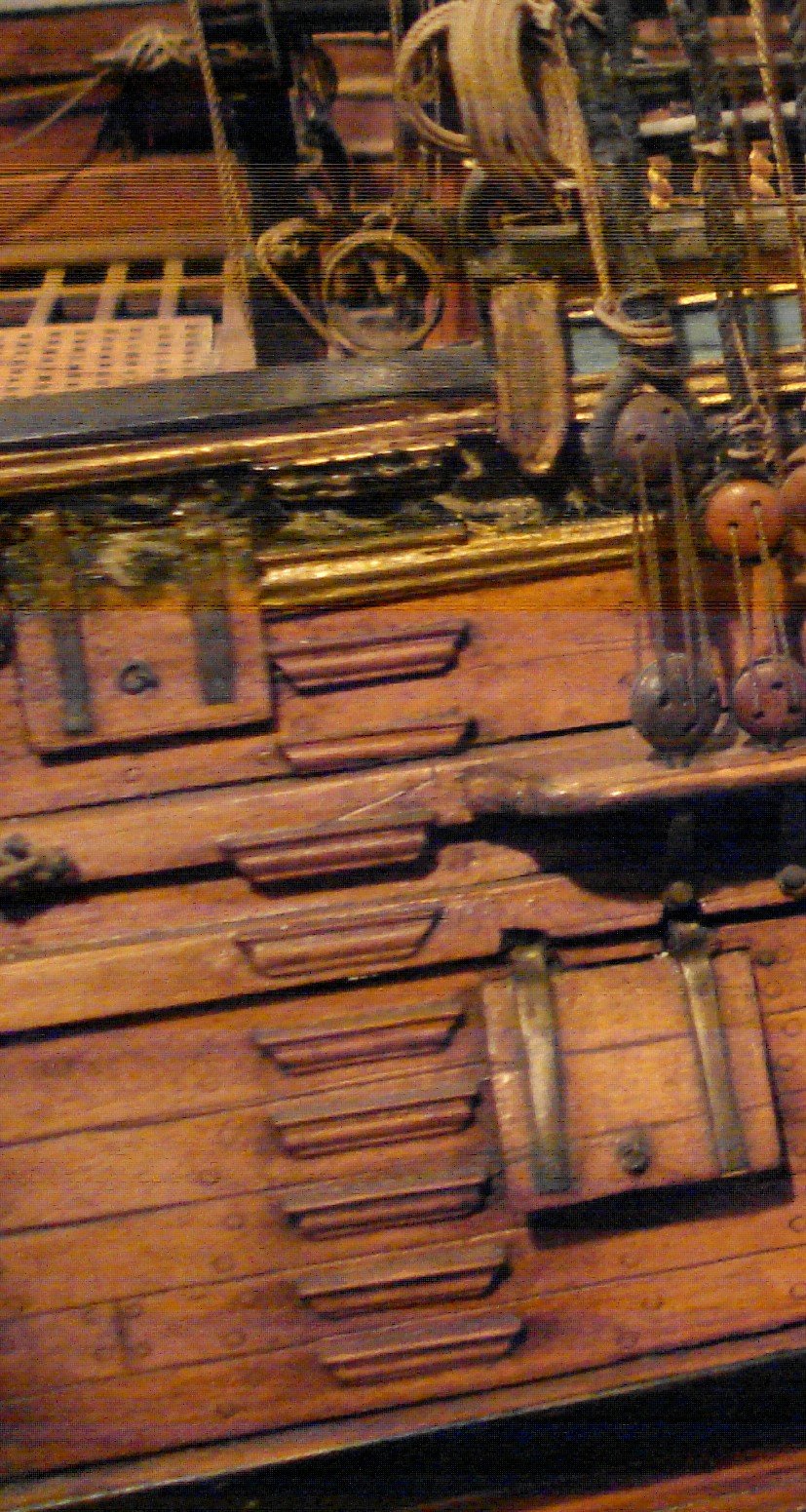
I have no idea if any of these are wrong and would not be surprised if the steps were in various configurations on the real ships. Is the photo of a contemporary model? Allan
-
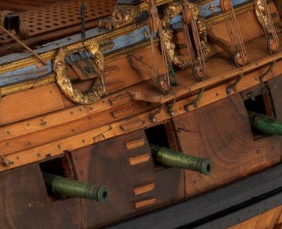
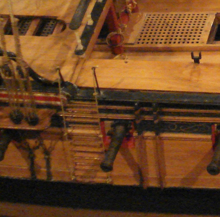
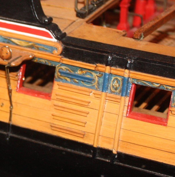
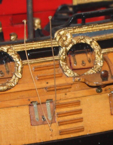
The below photos of contemporary models show steps on various vessels from the late 17th century to the late 18th century. Note the ropes on a couple of them are shown. There is also a photo of the Victory, modern day. I would like to think the steps are an accurate representation of how they were originally installed. Allan