
HOLIDAY DONATION DRIVE - SUPPORT MSW - DO YOUR PART TO KEEP THIS GREAT FORUM GOING! (Only 72 donations so far out of 49,000 members - Can we at least get 100? C'mon guys!)
×


allanyed
-
Posts
8,149 -
Joined
-
Last visited
Content Type
Profiles
Forums
Gallery
Events
Everything posted by allanyed
-
 Glenn, If your are building the Lady Nelson at scale 1:64 and with treenails for the decking at probably 3/4" or 1" diameter, they would only be about 0.011 to 0.015 in diameter. Even the Byrnes draw plate, which is an excellent piece, only goes to 0.016 diameter and it is difficult to make treenails this small in diameter even with bamboo. Scott Chambers suggestion above may be a good one with the right filler material. If the scale is indeed 1:64, drill holes in #78 or 80 size and fill with a wood filler that is a LITTLE different in color than the decking. Too much contrast will look like a case of the measles. At these small diameters even this method may not work so well. Showing deck treenails at this scale may not be a good idea at all. Some people, myself included, believe that oversized treenails look far worse than none at all. Maybe make a few test pieces and see how it looks using different methods then decide which, if any, you like. Allan
 -
Question on line size for lacing for small craft
allanyed replied to DonInAZ's topic in Masting, rigging and sails
Hi Don, My apologies, and I hate to do this, but have to start with a couple questions regarding your question. What approximate size, era, nationality are you referencing? You mention skiff, but is it truly a flat bottom boat like a skiff or some other type of small boat such as a ship's boat? If you are working on something like a ship's boat from yesteryear the following may be of some help. The line sizes varied with the size of the boats themselves. Examples of long boat, yawl, and pinnace standing and running rigging sizes for British ships can be found in Mays' The Boars of Men of Way. A couple examples - Main sail halyards for a longboat of about 30 feet had a 2" circumference where as a longboat of about 21 feet on a fifth rate was 1.5" circumference. Same sizes applied to the sheets. But, the jib halyards for a 31 foot long boat was 2" circumference and the sheets were 2.5" circumference. For a 21 foot long boat, both the jib halyard and sheets were 1.5" Standing rigging was larger. Shrouds for a 31 foot long boat were 4" circumference and for a 21 foot longboat 3". He also lists wooden hoops on the mast as sails were not laced directly to the mast. Allan -
Beautiful painting Wefalck!! Allan
-
Tony, I really have no idea on how it would be stowed, but I would think it would be stowed forward, under a thwart. If the bow area is closed off between the stem and forward most thwart, perhaps under there, so it is out of the way along with the rode and line. Regardless, I would want it to be at least a little visible on the model as it looks great! Allan
-
Paint for Models
allanyed replied to silbchris's topic in Building, Framing, Planking and plating a ships hull and deck
Chris, Did you consider asking a licensed allergist physician or even your family practice physician? Allan -
Gerard, I second Lou's response. I was lucky to meet Jim some years ago at his shop when I was in his area on a business trip and he gave me a great tour on building a thickness sander which I ordered by the time we were done. Same for Chuck, when I was living in NJ I was fortunate to attend a number of model club meetings in north New Jersey where Chuck has been a very very active member. He was giving great tutorials long before he jumped into his current business. You will not be disappointed. Allan
-
Shotlocker Sorry, but I have to throw this one in to you being from Indiana, PA. I remember some fine times at Patti's (I think on Philadelphia Street) some 50+ years ago when coming in for weekends to visit my then girlfriend (now wife of 50 years.) Anax While this is a light gun compared to what is found on Sovereign of the Seas it does show four live or rolling trucks, not two. https://collections.rmg.co.uk/collections/objects/36827.html Drawings of guns in The Restoration Warship by Richard Endsor, which is centered on Lenox (1677), shows drawings with four rolling, or live trucks for demi-cannon on the gun deck and two live trucks and two dead trucks on demi-culverin on the upper deck. Swan, 1693 had dead trucks and live trucks on small carriages as did one or more of the thirty ships of 1677. Either way, the guns recoiled and would require a breeching rope, running rigging to bring the gun back into position for firing and rigging to bring them inboard as well when finished being in use. The model of the 1655 fourth rate at Preble Hall shows that the guns are rigged but I do not have any closeups where one can see the rigging other than the breeching ropes. The carriages on this model appear to use four live trucks on the upper deck. The following from John Seller's Sea Gunner's Companion 1691 shows live trucks but no rigging. His book may have other drawings with both live and dead trucks. The book itself may have details on rigging if you can find access to a copy. Choosing live and/or dead trucks and proper rigging for the 1640 era, hopefully someone here at MSW will have more concrete information. Sorry this is not at all conclusive, but hopefully will be a little bit of help to you. Allan

-
Twisting blade on MicroMark saw?
allanyed replied to Rcboater Bill's topic in Modeling tools and Workshop Equipment
I have been using a MM table saw for many years with little to no issues. With the exception of using very thin, fine tooth blades for cutting shallow kerfs/slots/grooves for making gratings as described by Frolich in The Art of Ship Modeling (pp.117-119) I always use carbide tipped blades that are thicker. It makes more sawdust, but zero issues with the blade wobbling. Allan -
Bonjour Besson and welcome to MSW. Someone will no doubt reply that this an English only forum but I hope you stay with us. In the meantime I have an edited Google translation of your note below. pas de quoi, ciao, cheers, &c. Allan Hello to all friends on the other side of the Atlantic. You have here a very elaborate forum full of tips and building techniques. I discovered this site through Pinterest and I don't regret it. I started model making a long time ago (alas) by building radio controlled planes which fell too often !. In love with the sea, I therefore relied on boats sailing and sinking only very rarely. After an interruption of a good decade of this leisure for professional reasons, one day, while surfing the net, I had the opportunity to discover photographs of models of 18th century ships built with the framework represented in the Admiralty method. There, it was a great shock. The complexity and finesse of the work of the model makers presenting their work made me fall in admiration for such great successes. I asked myself the question of knowing if I would be able to arrive at the lowest rung of the ladder of these of these men. So I first looked at all the books dealing with the construction of vessels and in this matter there is something to read. It already took me two good years and at the same time I tried to make a small boat following a plan of Chapman. This experience, which was far from perfect, did not discourage me and I decided to embark on the adventure of the "Big Belly" which had a forum at the time, which like the yours, allowed the model makers to present the progress of their model and to glean the information necessary for the good completion of their model. I spent five years to build the hull and it is not completely finished because I moved by changing the region and the fittings of my new house stopped the construction of my model. However the demon of model making begins to recover me and I would like to start again with a small model of longboat in kit (the pre-cut members will relieve my joints of 72 springs) So there you are, if the shipments can be made to Europe, I would be delighted to join you. Good evening to all
-
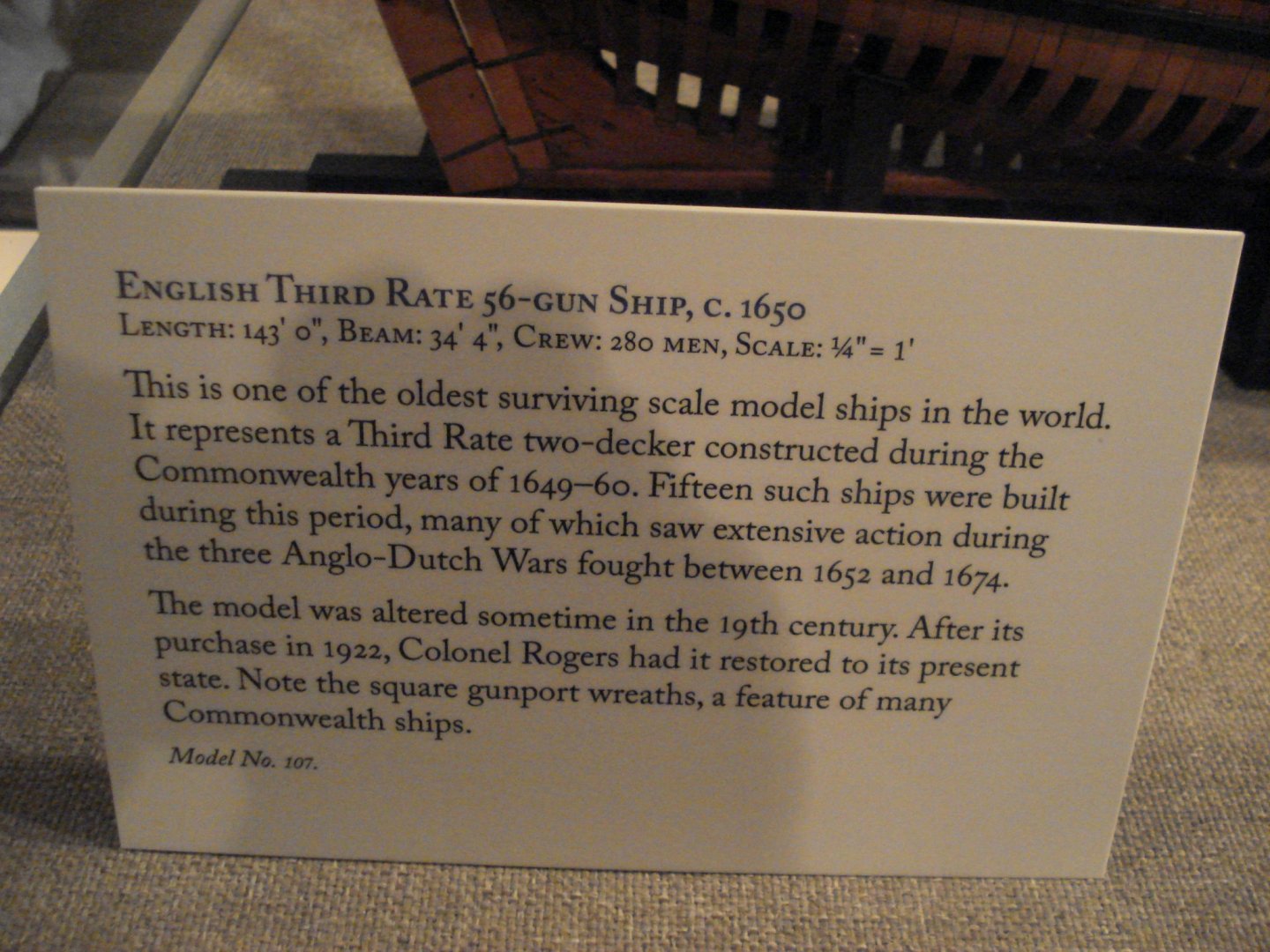
Phil, The following is the description given of the model at Preble Hall. Sorry, that is all have on that model. I took the photos during my last visit to Annapolis, 9 years ago. Maybe time for a repeat visit!!! Et Tosti, Wayne Kempson and I were very lucky and had Grant Walker spend an hour with us during our visit. That was a thrill in itself! Allan
-
Welcome to MSW gxsdent59. If you would be so kind, please let us know a name (real or made up) by which we can address you? Thanx! Allan
-
Thanks Mark, this was definitely my mistake and my apologies to Phil. Your additional photo is much clearer and I made the deadly mistake of "assuming" based on the other model photos. I had never before seen pins in the beakhead rail, but that is no excuse for making an assumption. As you point out, is this inclusion of the pins the way it was on ships of that era? Thanks again for pointing this out. Cheers Allan
-
Hello Phil, There are timberheads that come up and through the beakhead rail that you mention, thus no pins. Cheers Allan
-
Straightening aftermarket rigging line
allanyed replied to DonInAZ's topic in Masting, rigging and sails
Found this in the American Bee Journal. "As beeswax is the primary construction material of the beehive, its chemical composition is integral to how the hive functions. This same material, the storage location of food resources and developing brood, must be relatively non-reactive, so beeswax’s neutral pH (7) suits the need perfectly." Allan -
James, I am sure there are many suppliers to be found on line. (below is a link to Amazon). I bought some tiny LEDs some years ago, but was very happy that I went to the store that had them. I had no idea there were so many choices and most were not what I wanted/needed. Going to the store and speaking with a person that was something of an expert saved me a lot of problems. These have been discussed here at MSW on a few occasions so I am sure there will be more helpful posts responding to you. In the meantime..... https://www.amazon.com/EDGELEC-Flickering-Flicking-Emitting-Resistors/dp/B077XDPXNT/ref=asc_df_B077XDPXNT/?tag=hyprod-20&linkCode=df0&hvadid=241869999306&hvpos=1o2&hvnetw=g&hvrand=590792892296286093&hvpone=&hvptwo=&hvqmt=&hvdev=c&hvdvcmdl=&hvlocint=&hvlocphy=9012276&hvtargid=pla-425206898351&psc=1 Allan
-
Ian, What kind of information are you looking for? Is your build a scratch build or from a kit? There are drawings from NMM of the Slade's Arrogant (1761) class ships including Vanguard (1787). AOS has a book on the Bellona (1760) which is also a Slade design 74. As it was launched only a year before Arrogant, maybe some of the information in that book would be useful. Allan
-
Welcome Bob!! I enjoyed your story very much. Wish all new members would share a few of their own stories as well as you did. I have a nephew in the Coast Guard and his brother's wife is also in the Coast Guard. Great awakening for them both as they had been stationed in the Tampa area, then Hawaii, then Houston, and now in DC and North Carolina. This is the first time either had ever seen snow! I told them to look out, they could wind up in NJ or Alaska and what they have for winter now is nothing. Cheers Allan
-
Hello Steve, According to James Lees' book The Masting and Rigging of English Ships of War, page 159, jackstays on the yards were introduced in 1811. If this is correct for a bark such as Endeavour as well, and as she was launched in 1764 and eventually scuttled in Newport, Rhode Island in 1778, there would have been no jackstays on the yards. Photos of the model of Endeavour at NMM which was rigged by Mr. Lees does not show jackstays. I am sure there are others here with a lot more information on Endeavour that may be of more help to you. Allan
-
Thanks for those postings Alan! There are a lot of great documents out there but finding them is not so easy at times. One of my favorites is the following that I stumbled on when studying Captain Blackwood as part of the Euryalus project. TO CAPTAIN THE HON. HENRY BLACKWOOD, H.M. SHIP, EURYALUS. [From " Blackwood's Magazine" , for July, 1833.] Victory, October 10th, 1805. My dear Blackwood, Keep your five Frigates, Weazle and Pickle, and let me know every movement. I rely on you, that we can't miss getting hold of them, and I will give them such a shaking as they never yet experienced; at least I will lay down my life in the attempt. We are a very powerful Fleet, and not to be held cheap. I have told Parker, and do you direct Ships bringing information of their coming out, to fire guns every three minutes by the watch, and in the night to fire off rockets, if they have them, from the mast-head. I have nothing more to say, than I hope they will sail to-night. Ever yours most faithfully, NELSON &BRONTE. Cadiz East 13 Leagues

-
Gluing the boltropes to the sails
allanyed replied to Oliver24's topic in Masting, rigging and sails
Oliver, On the models I have made with sails, I sewed the bolt ropes on the sails so glue was not necessary. If you are going to use glue, I would avoid CA as it could leave a stain around the edge of the sail and will leave the edge of the sail brittle. Allan -
Harv, Keep in mind that even if there is no rabbet that can be cut into the model, the wales should taper to the same thickness as the planking above and below where they end at the stem. If there were a rabbet and they were not tapered, the rabbet would have needed to be a different width at the wales and that was not the case as far as I have ever seen. I am curious about the bow area in the photo. Does anyone know if the planking over this area is something called for in the kit? Allan
-
Hi Bob Sorry for the delay, just now saw your post. I got the drawings from the Library of Congress. https://www.loc.gov/resource/hhh.ma1719.photos/?sp=1&st=gallery Click on [ Drawings from Survey HAER MA-168 ] which is on the left side of the page that opens a little down from the top, and they all come up. They are free. There are a ton of photos as well. She is sometimes referred to Ernestina as well as her name was changed when she was sold in the 40's. PM if you have a problem and I can forward the drawings to you. Allan
- 86 replies
-
- 2
-

-
- schooner
- effie m morrisey
- (and 1 more)
-
Welcome to this motley crew of ours Max. Tell us a little about yourself and if you are working on a project that you would care to share. Allan
-
Welcome aboard! If you start a build log as mentioned above, I am sure you will get plenty of feedback on planking. Also, please read the planking tutorials here at MSW, they will probably answer many of your questions and help you avoid problems. Allan
