


allanyed
-
Posts
8,149 -
Joined
-
Last visited
Content Type
Profiles
Forums
Gallery
Events
Everything posted by allanyed
-
Welcome Al, When this pandemic goes away, you may want to look at joining the northern NJ modeling club. All types of skill levels and builds from that august group. I believe they are listed on this site regarding meetings and such. In the meantime, read as many articles here as you can, including the planking tutorials and build logs of similar vessels. The amount of information available here is incredible!! Allan
-
Welcome aboard Romulus, and thank you very much for sharing a little about yourself. Your profession got me to wondering what professions are covered across our membership of over 30,000. I imagine it is quite diverse and extremely interesting. Again Bine ati venit Allan
-
Jim I believe you are in very good company using gouache and watercolors, including at least two of my all time favorites, Carl Evers and Andrew Wyeth, both of whom used this combination extensively. Allan
-
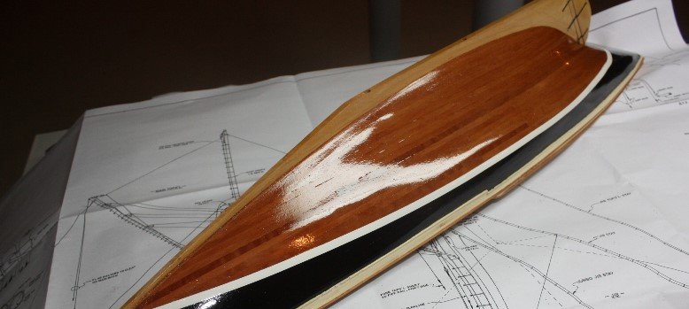
 Geert She is a very nice choice for a model, certainly not one that has been done many times and a lovely job you have done on her. Hope you don't mind my question, but did you bevel the edges of the planks at all, especially where the curve of the frames is extreme? Sketch below shows what I mean. Thanks Allan
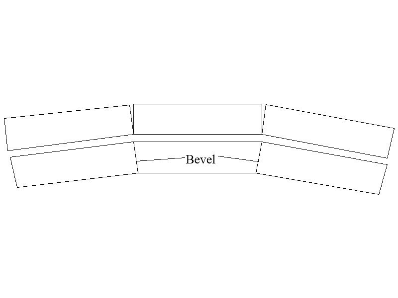
-
Deadeyes and ratlines and shrouds, oh my!
allanyed replied to Brewerpaul's topic in Masting, rigging and sails
Paul, Lees gives a description on pages 42 and 46 in Masting and Rigging of English Ships of War. The following is paraphrased. Pendants of tackles were fitted each side of the main mast and foremast. In large ships there were two a side and in ships smaller than 50 guns, only one per side. When the two pairs were used they are set up like the pairs of shrouds. When one per side, they were individual and each used an eye splice (like the swifter) They are served their entire length and after the 17th century are of a length that they would end at about the level of the upper catharpins. Up to 1780 a single block was spliced into the end. After that a thimble was used. When there are two pendants per side, the aft ones are one foot longer than the forward ones. Allan -
Deadeyes and ratlines and shrouds, oh my!
allanyed replied to Brewerpaul's topic in Masting, rigging and sails
Paul, Further to Marks, comments, and I am not sure, but it sounds like you plan to attach a deadeye to one end for, say, the starboard side, then take it up and back down to the opposing deadeye on the port side. This is not correct. If even numbers of shrouds, they are set up in pairs, the first being forward most on the starboard side, then a pair port, next pair starboard, next port, &c. If odd, the aft most shroud (a swifter) is done singular, one on each side, most often with an eye splice for each. This is based on the British navy, but it may be similar if not the same for the Constitution. Keep in mind the order of dressing. Again based on British ships, before 1810, If you are including the pendants of tackles they go on before the shrouds, then the shrouds, then the stay and then the preventer stay. Allan -
Bob, there are photos of contemporary models, sketches, and comments in Franklin's book Navy Board Models on pages 156 and 159 clearly showing and explaining that there are rotating pieces and clasps for the ensign staff. The clasp was opened and the ensign staff rotated forward and down to the deck. Allan
-
Super congratulations Jim! I have been back to the Academy quite a few times since graduation, but not recently. Wish I had known about your event and could have timed one of my business trips to NY to coincide. Did you happen to get a copy of the book and if yes, is it a good read? Cheers Allan
-
Mark, Your attention to detail and facts based on actual research of contemporary sources is fantastic and I, for one, very much appreciate the time and effort I am sure you take to do this kind of research. Allan
-
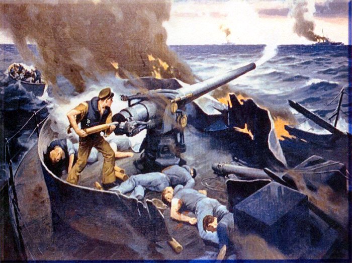
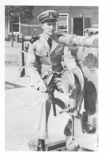
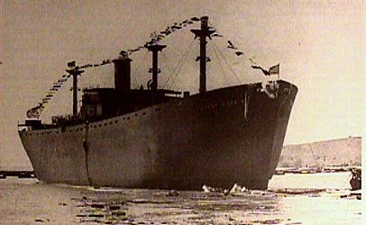
Hi Jim, good to see you back. Your latest paintings reminded me of one of my merchant mariner heros, Edwin O'Hara for which the athletic hall at the US Merchant Marine Academy in Kings Point, NY is named. He was an 18 year old cadet of the SS Stephen Hopkins which was in a surface battle with a German ship in 1942. The Hopkins went down with much of her crew, including O'Hara who took over the manning of their 4" gun prior to going down. I believe the Hopkins was the only Liberty Ship credited with sinking a German ship as the German ship Stier was so heavily damaged by the Hopkins that she was scuttled. The painting below can be seen at the academy and I thought as an artist you would appreciate this tribute to O'Hara. Cadet Edwin O'HaraSS Stephen Hopkins
-
Welcome aboard Cricket. Good to see such lovely work as yours. I for one am looking forward to seeing more of your work. Allan
-
Richard, Shame on me for not spotting your build log before now. Your attention to detail is awesome. I will be referencing it for sure the next time a schooner project comes in. Allan
-
Second planking
allanyed replied to Gremreeper1967's topic in Building, Framing, Planking and plating a ships hull and deck
My preference is as Chuck states, do the wales first, with one exception, that is if the wales are to be anchor stock or top and butt planks. In that case I install the top strake of the lower thick stuff as a guide for the wales. The top edge of the thick stuff will make it easier to form the curved bottom edge of the wales pieces. Allan -
Closed Hearts and ‚Infinite‘ Lashing
allanyed replied to captain_hook's topic in Masting, rigging and sails
Hello Hook From Lees Masting and Rigging, page 40. When hearts were used, the lanyard was spliced into the upper heart, then rove through alternate hearts, using as many turns as the heart would allow or until the lanyard was used up. The end of the lanyard was seized to the turn of the lanyard adjacent to itself with a couple of seizings. Allan -
Anchor Question
allanyed replied to rlb's topic in Discussion for a Ship's Deck Furniture, Guns, boats and other Fittings
Rib, This video may be of some interest to you. High temp silicone molds are easy to make. I have used pewter and melted it with a propane torch directly in a ladle so costs of equipment are negligible. You can also forgo the pewter or similar casting metal and use two part resin with most any silicone mold that you make. There are dyes that you can get to make the resin black before pouring. Would not have to be a high temp version. Allan -
Newbie from SanAndres Island
allanyed replied to Beat to quaters's topic in New member Introductions
Beat to Quarters -- Any name you can share by which we can address you? Took a quick look on the 'net about San Andres. Your island has had some interesting visitors, from Columbus to Henry Morgan. Sounds like a beautiful place on earth to be living. Welcome to MSW!!! Allan -
Welcome to MSW David! Let us know a little about yourself and if you have any projects going on. There are thousands of potential helpers here should you need any!! Allan
-
Thanks for sharing these. How does one get to Norfolk Island? Looking at maps, it seems to be rather small and quite a distance from both NZ and Australia. Allan
-
Les, If you are not set up for carving in wood, some clays are an alternative. Look at the build log of the Royal Katherine by Doris as she goes into a lot of detail on decorations using clay. Allan
-
Welcome aboard Doug. For tape bleed...… put on the tape, then, with brush or spray, coat the edges of the tape where the paint is to be applied with a clear finish that is compatible with the material, be it wood or plastic. This will seal the edge and prevent bleeding under the tape. Once dry, paint the color you want. Once the paint is dry, remove the tape and you will have a clean sharp edge. I have used masking tape and pin striping tape, the latter doing a better job. Many auto parts stores carry pin striping tape so not hard to find and it comes in several widths and colors. Another use for pin striping, at least for larger scales, is a final striping material. Several coats of a clear finish over the tape will soften the edge. The tape holds up very well. The model of Columbia has literally been at sea on the Allure of the Seas since she was launched in 2009 with no ill effects. Photo below shows her hull with the white pin stripe I used. Cheers, Allan
-
SCUPPERS
allanyed replied to samueljr's topic in Building, Framing, Planking and plating a ships hull and deck
Sam, What ship/era are you building? David Antscherl gives a very detailed explanation and drawings in volume II of The Fully Framed Model for the Swan Class Sloops of 1767-1780 on pages 73 and 74 but this may not apply to your ship if it is a totally different era, nationality, etc. Allan -
Not sure what you are looking for. Can you post some pics? The simple answer is wood glue, but it sounds like you are having some other problem such as holding the layer down on the frames while the glue dries. Allan
- 1 reply
-
- 1
-

-
How to rig spider lines on Spanish ship Sn Felipe
allanyed replied to dnevin's topic in Masting, rigging and sails
David, I am not familiar with Spanish ships, but English ships rarely had crows feet for the topmasts, (Lees Rigging and Fitting page 56) While the plans for the kit may call for them, this may not be accurate. Hopefully a member can cite a more reliable source as to their use. That aside, tensioning the crows feet is simply a matter of tightening using the blocks and line between the euphroe and stay. The sketch is similar to that shown in Lees for a main stay, but would surely be similar for the top mast crows feet. Allan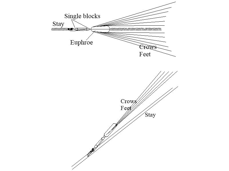
-
How to rig spider lines on Spanish ship Sn Felipe
allanyed replied to dnevin's topic in Masting, rigging and sails
David, Sorry to ask but what do you mean by spider lines? Not sure if you are referring to crows feet and the euphroe or something else. Allan -
Hi Wahka, As this is your first build, don't get discouraged, we all go through a long winding learning curve. Have you tried acetone? The argument continues for and against the use of CA and you may have just provided another reason not to use it. Some builders use it sparingly with success, others don't even have it in their shop. Lesson learned here I would guess. For the future, carpenters' glue such as Tite Bond or other brands is much easier to work with for any wood to be glued and can be soaked with alcohol or water to remove a piece if necessary and does clean up a bit more easily. Allan