


allanyed
-
Posts
8,149 -
Joined
-
Last visited
Content Type
Profiles
Forums
Gallery
Events
Everything posted by allanyed
-

Gun Spile
allanyed replied to Mark Allen's topic in Discussion for a Ship's Deck Furniture, Guns, boats and other Fittings
Bob, I am curious to the source on the rolling ball idea. To lubricate with olive oil, the barrels could be swabbed then tampioned. The olive oil will last a long time without having to have a ball rolling back and forth which carries it own problems such as knocking out the tampion as stated above and an extra step having to extract it before loading powder when going into action. May very well be what was done, but definitely a new one for me. Allan -
The contracts for five of the 130 foot group 50 gun British ships in the mid 1690s describe GD and UD clamps and GD spirketting as having Flemish hook and butt scarphs and tabled together. The exact wording for the gun deck spirketting is To be of Oake Four Inches Thick and Fourteen Inches Broad and Tabled in the Meeting Edges Two Inches one into ye Other and Scarphed Hooke and Butt Flemmish Fashion at least Four Foot Long. I understand coaking in the scarphs and rabbeting the two strakes together if it were called for, but I cannot find a definition or description of what is meant by tabling. To me it sounds like the edges are rabbeted together for the run of the strakes, but I do not recall ever seeing this term in the past so not sure what this would look like. Any help on this would be greatly appreciated. Allan
-
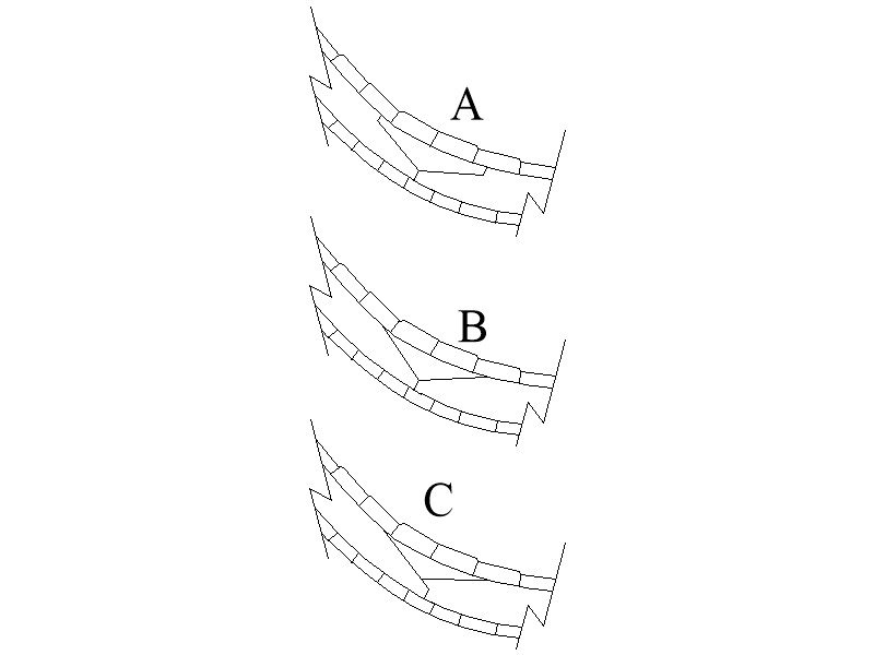
For a British ship circa 1690s I believe there were likely chocks at the joints of the futtocks. Drawings in The Restoration Warship by Richard Endsor, which is a thorough study of Lenox 1678, shows chocks that are triangular in shape and rather small. As I have learned, sharp corners were avoided as much as possible in ship building, thus it is possible that the chocks may have had shoulders. I have been unable to find contemporary information or close to contemporary for the late 17th century that describes the shape of the chocks, be they triangular or with shoulders. I would appreciate it if anyone can steer me to contemporary sources with details on these chocks. A sketch below is what I am puzzling over. In contrast to the use of chocks, Goodwin is clear by sketch and words that from 1650 to 1710, hook scarphs were used, not chocks. His sketches of chocks beginning in 1710 do have shoulders. Regardless of choice of chocks or scarphs, both can be argued to be correct based on these two sources, but I would love to find or hear about contemporary information as that would be the best way to make a decision. Just to throw another wrench into the mix, sketch C is of an actual joint on the Swedish ship Carolus XI 1678. This is probably not applicable, but I thought it was interesting. Allan
-
Ferit Are you referring to the Frigate Berlin 1674? Ships in the British Navy in the late 17th century had parrels with ribs and trucks on the foreyard, main yard, fore and main topsail yards, and on the starboard side of the mizen mast for the mizen yard for a lateen sail as the yard lay on the port side of the mast. A truss parrel superseded the parrel of the ribs and trucks on the mizen yard in abut 1773 (Lees Masting and Rigging, page 105). The topgallant yards were fitted the same way as the topsail yards until about 1805 then went to truss parrels. The cross jack had no parrels, but rather slings until 1773 at which time a truss was used. Allan
-
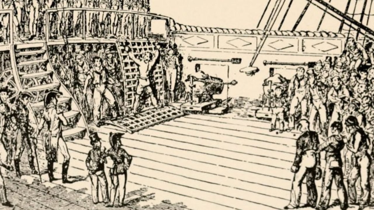
Doug, And sometimes they set a grating upright and tied a sailor to it for strokes from the cat as below. That would be an interesting scene to model. Allan
-
Duane, I did some checking and looking at the QD on Euryalus which carried 32 pounder carronades on her QD an FC, not all the top timbers carried to the top rail so there were indeed larger spaces similar to what you show. The inboard side did carry 2" planking. Allan
- 31 replies
-
- 4
-

-
- carronade
- model shipways
- (and 2 more)
-
Your workmanship is extremely clean, cudos!! Rather than paint the inboard side of the outer planking red, maybe install the inboard planking and leave it natural or paint it red. There also seems to be a lot of missing frames. Looks like there should be at least 3 or 4 additional frames between each of those that are in place. If you do add the inboard planking and add a cap rail, no need to add more frames as they will be hidden. Thanks for sharing your build. Allan
- 31 replies
-
- 5
-
-
- carronade
- model shipways
- (and 2 more)
-
Bearding Line Tapering
allanyed replied to AndyXO's topic in Building, Framing, Planking and plating a ships hull and deck
Andy, Is this a keel or is it the slotted backbone usually used in kits to hold the bulkheads? Tapering a keel can be done by drawing a fine pencil line long the centerline of the top or bottom of the keel then marking the 3mm (1.5mm from the center line), drawing a line to the 5mm wide point then tapering with plane, chisels, file, or sanding. The tapering should be done before the rabbet is made. I prefer planes and/or sanding but that is just my own personal choice. If it is the slotted centerboard that you are referring to, I am sorry I have no idea on tapering this other than sanding as I assume it is plywood. Allan -
How many rigging lines per belaying pin
allanyed replied to Mark Allen's topic in Masting, rigging and sails
Cheers Mark, I realize this is a reposting from the other string but hope it is OK to repeat an earlier response. I do not believe galleys of the 16th century such as the San Marcos ever had belaying pins. It seems you are at the mercy of an error by the kit manufacturer but it can be pointed out that on some contemporary models of the 17th century and 18th century, they do show more than one line secured to timberheads at times. Whether this is an indication of actual practice on board ship in those days I do not know. Allan- 1 reply
-
- 2
-
-
2019 NRG Conference Coverage
allanyed replied to TomShipModel's topic in NAUTICAL RESEARCH GUILD - News & Information
Tom, Thanks for sharing all the photos. I just looked through them again and all of a sudden I noticed the age range of the group. Maybe it is that the younger modelers are still working and could not get the time to attend, maybe not. I have no answer, but I do wonder how we can get more "youngsters" involved so the art does not die with the next couple generations. In this age of electronics, internet and fast results desired in the things they do, this may be a difficult thing. Maybe those here that are more in tune with social media can think of ways to get some interest from the "kids" out there. We have thousands of potential mentors here, just need more students. Allan -
Michael, My apologies if this was given before, but what is the clamp that you are using in the photos? Looks like a handy tool. If possible, please post a photo of the tool itself. Thank you very much. Allan
-
Gun Spile
allanyed replied to Mark Allen's topic in Discussion for a Ship's Deck Furniture, Guns, boats and other Fittings
Hi Mark, I have seen this on timberheads on the forecastle on some contemporary models such as the one pictured below. Regarding the San Marcos, I have doubts that there would be belaying pins on ships in the 16th century. Maybe the moderators can move your question to the rigging section and others more knowledgeable will respond with accurate information to help you. Allan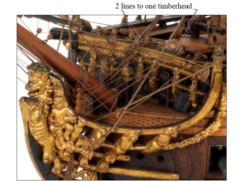
-
Anchors
allanyed replied to Nacioffi's topic in Discussion for a Ship's Deck Furniture, Guns, boats and other Fittings
I am sure you will do well in making them. I do think though that there will be at least two, perhaps three different sizes considering bowers, sheet and perhaps kedge anchors. Allan -
Anchors
allanyed replied to Nacioffi's topic in Discussion for a Ship's Deck Furniture, Guns, boats and other Fittings
Nacioffi Which anchors do you need? I believe there are four anchors on Victory at this time in various sizes but Lavery states that 1st rates carried five until an order of 1779 stipulated they carry only four. They are not that difficult to make so you will likely get better scale accuracy making your own once you have the proper dimensions of each. They can be made with cast metal and wood stocks or all from wood with the "iron" portions painted black. I have no information on the weights of Victory's anchors but anchors were normally sized in proportion to the tonnage of the vessel. There are drawings of anchors of various sizes the RMG collections that you can find on-line as well as dimension details in spread sheet form in Brian Lavery's Arming and Fitting of English Ships of War. Allan -
Gun Spile
allanyed replied to Mark Allen's topic in Discussion for a Ship's Deck Furniture, Guns, boats and other Fittings
Alan, Thank you for sharing the drawings. What is the purpose of the traversing plate? I do not recall ever seeing this before. Thanks again Allan -
Brush painting hull ??
allanyed replied to CPDDET's topic in Painting, finishing and weathering products and techniques
Dave, Once the surface is sanded perfectly smooth, draw the line and paint the first color, the lighter shade first. This first color should actually go past the line. Then redraw the line if necessary and a lay down a tape along the line. Next, put on a coat by spray, or by hand, a clear varnish, clear nail polish, or similar along the tape edge to seal it. Once this clear coat is dry, it will prevent t bleeding and wicking under the tape when you paint on the second color. Paint at an angle but away from the edge of the tape so you are not forcing paint into the seam. Again, be sure the surface is absolutely free of bumps and dings so there is no open gap between the tape and wood before sealing and then painting. If there is to be a thin (1/8", 1/4" or similar) white or other color stripe between the two main colors, automobile pin striping tape works very well. Once in place, clear coats over the finished hull will protect the tape. I used the pin striping on the model of the schooner Columbia and it shows no sign of ill effects after ten years aboard a cruise ship. Allan -
I have this book and reference it quite often. In addition to quite a few drawings it has scantlings of quite a few boats and charts of what boats were found on various size vessels at various times. It is well worth owning!! Allan
-
CofF Finding sails that are of scale thickness in woven cloth is difficult. Silkspan is a great substitute in general but high thread count bed sheets or pillow cases (800 or more TPI) look good and if they are to be furled, you can cut them short so they are not too bulky when furled. Allan
-
A smooth surface prep as mentioned above is key. If you are painting a long line such as a water line or some such, and go with the masking tape method, coat the tape edge with a clear varnish or similar coating to seal the edge so there is less chance of the paint wicking under the tape and leaving tiny points or runs. Once the paint varnish is dry, apply the paint and once it is completely dry, the tape will come off leaving a sharp line. Same treatment works well with hand made stencils if they are being used for lettering. Use high quality brushes for the fine work!! Allan
-
nubie question regarding string and knots
allanyed replied to EricWilliamMarshall's topic in Masting, rigging and sails
If you befriend your barber/hair stylist, get an old pair of their hair cutting scissors and have professionally sharpened. He/she will have such a contact. They are extremely good at snipping the ends without a trace of a tail and will last for years. Better is to get a new pair but top quality scissors will be well over $100. In the end, as with most things, you get what you pay for. Allan -
Gun Spile
allanyed replied to Mark Allen's topic in Discussion for a Ship's Deck Furniture, Guns, boats and other Fittings
Hi Mark, That is what this site is all about, helping, getting help, teaching, learning and overall having fun! Allan -
Gun Spile
allanyed replied to Mark Allen's topic in Discussion for a Ship's Deck Furniture, Guns, boats and other Fittings
Hi Mark, Can you send a picture? When you mention wheel chocks it made me think of the quoins which are used to change the elevation of the cannon aiming point by pushing them in or out under the inboard end of the barrel (not the trucks) See below. Spile could just be a bad translation --looking up spile I found the following: a small wooden peg or spigot for stopping a cask. 2 a large, heavy timber driven into the ground to support a superstructure. . Is this what they are showng? Allan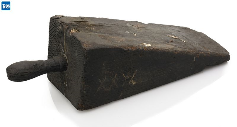
-
Add up the cost of the wood cut in sheets and strips (strips are not so important as there are so many spiled and/or tapered strakes on the hull and decks) and compare it to the cost of rough cut board stock, a small format band saw or a simple table saw, and thickness sander. It may be equal to buying pre-cut sheets and strips for a good size model. Plus you would then have tools that can be used for years so the cost is amortized over a lot of models and time. With these tools and board stock you can use any of the woods mentioned including Castello or European box at a much more reasonable price. Castello and box as well as poplar (when you can find clear white stock) is dear, but better priced with board stock than sheets and strips. I have the privilege of owning a planer as well, which I highly recommend, but lived without it for a long time. Yes, there is a lot of sawdust to be made when cutting your own, but it is the same for the company selling you the finished sheets and strips. You are paying for that sawdust regardless of who makes it, them or you. Just my two cents worth. Allan
-
odd number of deadeyes per side
allanyed replied to jeff watts's topic in Masting, rigging and sails
You may want to check Longridge's Anatomy of Nelson's ships as he shows quite detailed of the shrouds. I am traveling with no access to my books so cannot speak of Victory's time period, but for earlier periods, the order of dressing as given by Lees is Pendant of the tackles, shrouds, swifter (this is the aft most unpaired shroud with deadeyes) and stay. He also describes use of an eye as mentioned by Wefalck, but again, it may not be contemporary to Victory. The swifter did not receive ratlines in earlier periods but I don't know if that is the case for Victory. Allan -
Ciao Daniel Just checked in on your build and am enjoying your postings. I wish I had see it from the beginning and could have met with you in person as I travel to Treviglio twice a year for work. Alas, I am semi-retiring in January but MAYBE will be there for a few days in March and would love to see your work in person. Beautiful workmanship!!!! Allan