


allanyed
-
Posts
8,149 -
Joined
-
Last visited
Content Type
Profiles
Forums
Gallery
Events
Everything posted by allanyed
-
 Sorry for the very late reply, been traveling a bit this past week. 1. what rubber mould brand did you use? I used Micro-Mark 1-to-1/ Rapid RTV Silicone, and it was surprisingly fragile. You can see how it broke out in the mould I showed earlier. Did you find something more durable? I purchased molding and casting materials from Polytek (https://www.polytek.com/) They were extremely helpful in selecting the right materials a they have many. The next time I am in need I will likely use them again. 2. Did you provide any vents for gasses, or is it not needed with such a simple form? No vents were used, but I was careful to tap and vibrate the mold for some minutes to bring any air to the top. 3. When you pour the metal, do you leave the rubber mould in its forming box so it doesn't distort? Yes, for both resin or metal. For the resin I left the material in the mold for some hours to be sure it was cured. For metal, I left it until cool enough to touch without burning fingers. 4. Do you use the Micro Mark lead free pewter? The pewter was given to me by a friend/client some years back. Their business is machining to make a variety of molds and items and had a lot of experience with materials, but I don't know any details on the metal itself. They gave me about 5 or 10 pounds of the stuff so enough for a LOT of cannon barrels. FYI If you go to resin, there are dies that can be added to make black barrels rather than painting, but I have not tried it. Allan
 -
I may be going out on a limb, but I think you are correct, there is no such rigging as shown in the photo. Crow's feet of various designs were used in this area on many nationalities' ships. I have not seen any description (so far) of rigging as shown in the photo you posted in Lees, Anderson, or other credible sources. The crow's feet came in a variety of designs from simple to complex. The sketch below I THINK is more typical than that shown in the photo. Where the photo shows knots, there would be blocks, and where the photo shows a single block, there likely would be a long block. Is this model a kit of the Gallicia or some other vessel? Allan
-
Mark One more option that you may want to consider. I have never been able to cast the cannon with a mold made of two sides without a seam, no matter how careful and accurate the molds are made. They have to be filed and finished which takes a lot of time and there is still the possibility of leaving filing and finishing marks on the surface. I experimented and succeed using a one piece silicone rubber mold that eliminated the seam. The barrels can be removed with little effort and no damage to the mold in my experience. I tried both lead free pewter and casting resin. Both worked well. The only part that creates a problem are the trunnions which I added to the cast barrels separately as can be seen in the photo of the casting resin barrel. Just another idea you might want to consider.
-
Just one more to throw in. The following close up shows lines secured to a rail. This same model of a British fourth rate from 1695 has several running rigging lines made fast to the belfry rail as well. Allan
-
Thank you gentlemen. I did purchase higher resolution photos of a 1695 50 gun fourth rate from NMM and they are somewhat of a help, albeit not as good as actually having a chance to stand in front of the model and drawing the belaying points for each line. With these photos, Lees, Anderson and a myriad of other sources, I do hope it will be as detailed and accurate as possible. There are some conflicts between the sources, but I believe that is not unusual when doing any kind of research in this hobby of ours. Allan
-
I am looking for definitive information on running rigging belaying points for a fourth rate of 1695. I have scoured Lees and Anderson and there is a lot of information there that is helpful, but in the words of R.C. Anderson It would be impossible - for me at any rate - to give a complete list of the type and position of the fastening of every rope. It is many years since he wrote that statement so I am hoping someone can lead me to THE definitive source on belaying points for this era. There is a model of a 50 gun fourth rate of 1693 (possibly the Portland), and a model of a 60 gun of 1703 at Annapolis for which I have photos from the past but I only have a few photos and they were not taken with the thoughts of following running rigging lines. If necessary I will have to go back up to Maryland and spend a day or two photographing and sketching lines, but would love to avoid that if possible. There is a fully rigged model of a 50 gun of 1695 at NMM, but going there and getting to the model and taking photos is probably not possible. Any leads, information, and help of any kind would be most welcome. Allan
-
Cross Jack brace pendants and braces
allanyed replied to allanyed's topic in Masting, rigging and sails
Thanks Dave. This makes sense and I have strong doubts that the figures in Steel would be that far off so will go with that information. Regarding rounding to the nearest 1/2", even if that is not the case for real world sizing, it is likely fine for 3/16" or 1/4" scaling. Those were my thoughts for when it comes time to make or buy rope. Allan -
I think Lees has erred in his formula regarding brace pendants and braces, but who am I to judge? Again, reference is to Litchfield, a fourth rate of 1695. For the main yard brace, using his calculations, the pendant is 4" circumference, the brace is 2 1/4" circumference. The foreyard brace pendant is 3 1/8" and the brace itself is 1 7/8" (I have rounded to the nearest 1/8th.) Now is the problem, using his calculations, the cross jack brace pendant is 5" and the brace is 2 3/4" circumference. This makes not sense to me as the cross jack is much smaller than the lower main yard yet the brace pendants and braces are larger than both the foreyard and main yard brace pendants and braces. Any help will be greatly appreciated as always! Allan
-
Warner Dave makes a great point. Also, regarding your question, at least for English ships, it appears to be a similar fit. Lees states that an eye is formed so the stay is tight on the topgallant mast. Keep in mind it is tapered so if the eye is a bit small, it can be made to slide it down to the proper location on the mast. Might take a little fidgeting but should plenty tight enough. If you do want to use glue, a little watered down white glue or even carpenter's glue will do the trick. CA is not always the best "solution" to put on a line as it will make it brittle and probably discolored. Allan
-
Yes, Litchfield would have had two top ropes for each top mast thus two sheaves in the mast according to Anderson and Lees. Lees shows this relatively clearly on page 55. The main mast cap is approximately 9 feet about the trestle trees. He states that the length of the falls does not include the portion from the eye under the cap through the sheave and block at the cap. Thanks again to both of you for your thoughtful input. I have not rigged anything larger than a Gloucester schooner in 39 years, so this has carried a huge learning curve for me. Allan
-
Thanks to all of you! I just looked at Anderson and it may clarify a bit. He calls the top rope pendant a misnomer, and it is more of a runner with a block hooked on the end of the top rope and a tackle beneath it. He mentions that there should be a drift of about 10 feet between the block at the deck and the block at the "pendant". This is based on the model of the St. George. With a distance of 10 feet between blocks, the "pendants" will be about 40 feet long. Jan, my mistake, the main yard is actually 64' 4" long, and the foreyard is 57' 10" long. Length from the main mast cap to the upper gun deck is about 70'. I have no build log as I am still in the throes of my first real drawings from which the build will take place. Most of the drawings second draft are done for the hull and decks, frames, &c. as is the list of the hundreds of scantlings dimensions. Drawings and description of the rigging is probably the next 6 to 12 months effort. Hopefully will start to cut wood about that time. Couple basic drawings on progress below. The carvings designs are a compilation of ideas from multiple sources. Profile Litchfield 1695.PDF Framing disposition Litchfield 1695.PDF
-
Regarding Litchfield an English 4th rate of 1695. According to Lees (page 56) the top ropes were not un-rove at this time (before 1800) but rather left in place and rigged. My question is what is the length of the pendant? Lees states that the length for the top rope pendants are equal to the length of the lower yards. This makes no sense as the distance to the deck is about 40 feet and the main yard is about 70 feet long. To me, the pendants would have to be of such a length to allow the top rope falls to be rigged to the pendants and through their appropriate blocks at the deck. I am probably missing something obvious, but cannot come up with an answer. Any insight to this would be appreciated. Allan
-
internal framing
allanyed replied to rth385's topic in Building, Framing, Planking and plating a ships hull and deck
Sorry for the late reply everyone. I think Druxey and Wayne gave you the best information!! Thanks again for the input. Allan -
New member with a question about shipping models
allanyed replied to CJ2S's topic in New member Introductions
I used the following to get my model of Euryalus to Switzerland. There was MINOR damage that they had fixed to everyone's satisfaction and at no charge back to me or my client for the repair. I have used others for long distance shipping that were chosen by the clients that worked well and one that I told to get out when he asked if he could take off the masts and rigging in order to use a smaller crate!!! Be sure you are present when they pack it up. Craters & Freighters 333 Cedar Ave Middlesex, NJ 08846 732-56 Usual caveat that I have no financial or other interest in this company, just a successful experience in the past Allan -
Dave, Looks like a very nice piece of work!! What is the object on top of the cannon barrel near the area of the touch hole? As this is circa late 17th century, I assume it is not a gun lock as they did not come into use until 1718 in France and soon after in England. Again, very nice work. Allan
- 128 replies
-
- 2
-

-
- mordaunt
- battle station
- (and 1 more)
-
Good information, thanks for sharing. One oddity is that the dimensions are metric which was not used in shipbuilding at that time. No issue to convert, but surprising to me. Allan
-
With all due respect to others, there is no substitute for spiling. It is easy and avoids the pitfalls of edge setting completely. Add to this that if you ever go with box or other harder woods spiling is a must, so give it a go!! Allan
-
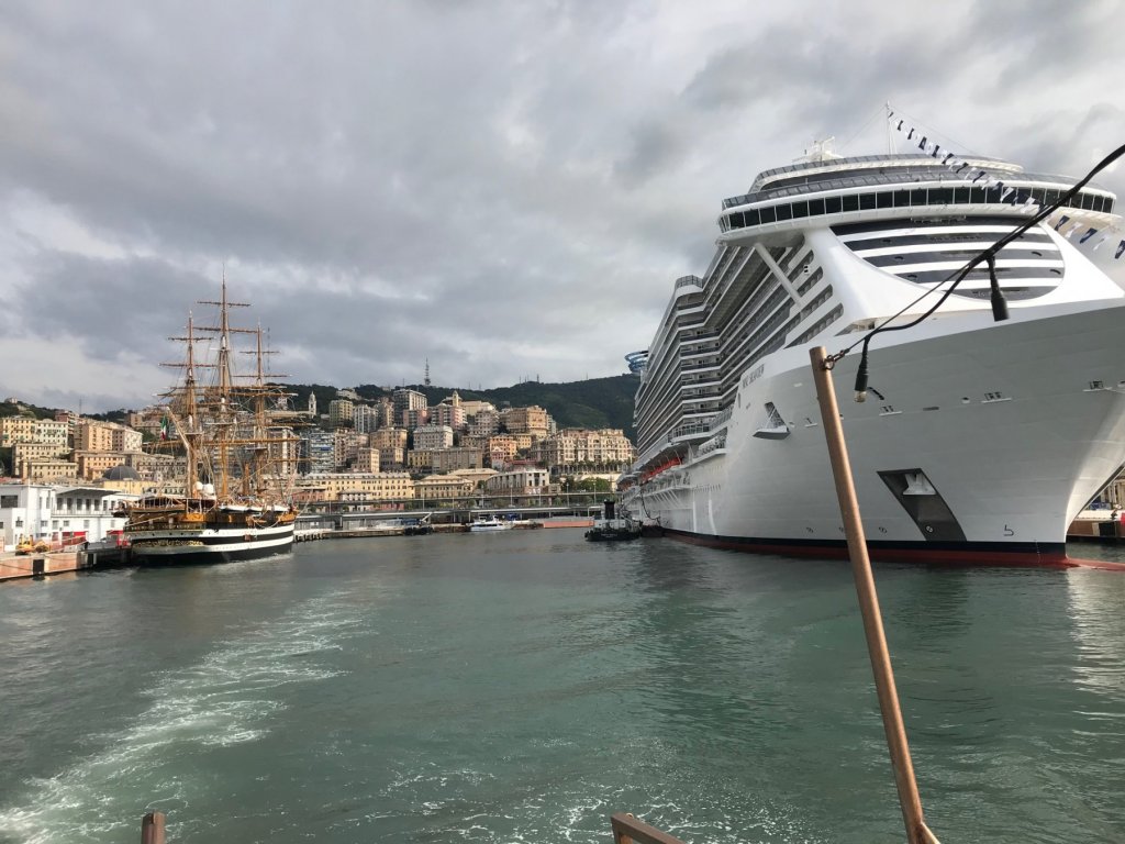
Caught this on my iPhone while heading to Portofino from Genoa harbor, Amerigo Vespucci and MSC Seaview (launched two weeks ago) I love the days of sail, but to sail on board, something new is pretty darn good! Allan
-
Sorry if this has been brought up before, I may have missed it. Your background set up is great. I have used light grey backdrop paper in the past and it makes for much cleaner pictures with no background clutter. Yours looks like a "small" enclosure with similar material. Unless you have a third arm and hand, you must have an assistant taking the pics. If that be the case, tell her these are great shots. Cudos all around the Tosti house! Allan
- 3,618 replies
-
- 3
-
-
- young america
- clipper
- (and 1 more)
-
Ed, I ran out of words to describe the beautiful work you have been doing a long time ago. The little things you have shared can be such a huge help. Not sure if it was mentioned previously as I have likely missed some posts, but the stand to hold the spares with the alligator clips is simple but brilliant. One of those background things to find while looking at the details on the rigging itself. Allan
- 3,618 replies
-
- 4
-
-
- young america
- clipper
- (and 1 more)
-
Submarine Blue. What is our name? To make trennals down to 0.875 real world, which is 0.018 diameter, bamboo is about the only wood that can be used consistently. Use a good quality draw plate such as from Jim Byrnes and you can make a couple hundred per hour. Undyed garden bamboo stakes can be split with a knife into thin strips down to the largest hole in the draw plate then run through consecutively smaller holes until you reach the diameter you want. Most hull planks are about 3 to 4 inches thick except for the wales and upper strakes, so 0.023 is an average trennal diameter at 1/4 scale. You will need upwards of 10,000 for a good sized frigate, so it will take a while but definitely can be done. Allan
-
Hi If you would be so kind, please give us a name by which to address you. There are several scratch builds on this site that may be a good start for you, including a cross section build of Triton and Echo, Triton complete vessel and more. The next steps would be to go to something more complex such as Naiad, Euryalus, Swann class, and quite a few others for which there are plans and books available and there is plenty of help from the members here at MSW! Where are you in Florida? There is a club in the Fort Myers area and plenty of members living here in Florida as well. Good luck! Allan
-
Snow, All of this is in Volume I of Euryalus (36) 1803. The bulk of the history is centered on her, not so much Trafalgar. I did months of research on Euryalus as I thought it would add to a book on just building the model and found so much information. I found letters home from a Lieutenant Henry Sibthorp to his family. He later transferred to the Ajax and drowned shortly thereafter during a battle in the Dardanelles. Also found a paper by Jill Chambers in the UK with details and record of Euryalus after she was hulked. She kindly let me use her research writings for the Euryalus book. Also found letters from her captain, Charles Napier during the War of 1812 where he challenged an American ship under Captain Charles Gordon to a duel. The weapon of choice was their ships! Needless to say, both Navies said the ships were not dueling weapons to be used as they saw fit so it did not happen. These papers came from a retired Archivist at the US National Archives, Stuart Butler who let me use his paper. I suspect there is as much or more regarding Victory and other ships from Trafalgar. The London Times has articles archived and on line and that was another source. It takes hours upon hours, but well worth the effort and it was a lot of fun. Follows is another letter from Collingwood Euryalus, off Cadiz, Oct. 24, 1805. SIR, - In my letter of the 22nd I detailed to you for the information of my Lords’ Commissioners of the Admiralty, the proceedings of his Majesty’s Squadron on the day of the action and that preceding it, since which I have had a continued series of misfortunes, but they are of a kind that human prudence could not possibly provide against or my skill prevent. On the 22nd, in the morning, a strong Southerly wind blew, with squally weather, which, however did not prevent the activity of the Officers and Seamen of such ships as were manageable from getting hold of many of the prizes (thirteen or fourteen), and towing them off to the Westward, when I ordered them to rendezvous round the Royal Sovereign, in tow by the Neptune; but on the 23rd the gale increased and the sea ran so high that many of them broke the tow rope, and drifted far to leeward before they were got hold of again; and some of them taking advantage in the dark and boisterous night, got before the wind, and have perhaps drifted upon the shore and sunk on the afternoon of that day; the remnant of the Combined Fleet, ten sail of ships who had not been much engaged, stood up to leeward of my shattered and straggled charge, as if meaning to attack them, which obliged me to collect a force out of the least injured ships and turn to leeward for their defence; all this retarded the progress of the hulks, and the bad weather continuing determined me to destroy all the leewardmost that could be cleared of the men, considering that keeping possession of the ships was a matter of little consequence compared with the chance of their falling again into the hands of the enemy; but even this was an arduous task in the high sea which was running. I hope, however, it was accomplished to a considerable extent; I entrusted it to skillful Officers, who would spare no pains to execute what was possible. The captain of the Prince and Neptune cleared the Trinidad and sunk her. Captains Hope, Baystun and Malsobes, who joined the Fleet this moment from Gibraltar, had the charge of destroying four others - The Redoubtable sank astern of the Swiftsure while in tow. The Santa, I have no doubt, is sunk, as her side was almost entirely beat in; and such is the shattered condition of the whole of them, that unless the weather moderates, I doubt whether I shall be able to carry a ship of them into port. I hope their Lordships will approve of what I (having only in consideration the destruction of the enemy’s fleet) have thought a measure of absolute necessity. I have taken Admiral Villeneuve into this ship; Vice Admiral Don Aliva is dead. Whenever the temper of the weather will permit and I can spare a frigate (for there were only four in the action with the fleet, Euryalus, Sirius, Phoebe, and Naiad; the Melpomene joined the 22nd and the Eurydice and Scout the 23rd), I shall collect the other Flag Officers and send them to England with their flags (if they do not all go to the bottom) to be laid at his Majesty’s feet. There were four thousand troops embarked under the command of General Contamin, who was taken with Admiral Villeneuve in the Bucentaure. I am, (Signed,) C. COLLINGWOOD. Cheers, Allan
-
Snow, The following is a transcription of the letter from Nelson to Blackwood and letter from Collingwood regarding the battle and the death of Nelson. TO CAPTAIN THE HON. HENRY BLACKWOOD, H.M. SHIP, EURYALUS. [From " Blackwood's Magazine" , for July, 1833.] Victory, October 10th, 1805. Cadiz, East, 13 Leagues. My dear Blackwood, Keep your five Frigates, Weazle and Pickle, and let me know every movement. I rely on you, that we can't miss getting hold of them, and I will give them such a shaking as they never yet experienced; at least I will lay down my life in the attempt. We are a very powerful Fleet, and not to be held cheap. I have told Parker, and do you direct Ships bringing information of their coming out, to fire guns every three minutes by the watch, and in the night to fire off rockets, if they have them, from the mast-head. I have nothing more to say, than I hope they will sail to-night. Ever yours most faithfully, NELSON AND BRONTE. THE LONDON GAZETTE EXTRA-ORDINARY. WEDNESDAY, Nov. 6, 1805. ADMIRALTY OFFICE, Nov. 6. Dispatches, of which the following are Copies, were received at the Admiralty this day, at one o'clock, A.M., from Vice-Admiral Collingwood, Commander-in-Chief of his Majesty's ships and vessels off Cadiz:- Euryalus, off Cape Trafalgar, Oct. 22, 1805. SIR, The ever-to-be-lamented death of Vice-Admiral, Lord Viscount NELSON, who in the late conflict with the enemy fell in the hour of victory, leaves to me the duty of informing my Lords Commissioners of the Admiralty that on the 19th instant it was communicated to the Commander-in-Chief, from the ships watching the motions of the enemy in Cadiz, that the combined fleet had put to sea; as they sailed with light winds Westerly, his Lordship concluded their destination was the Mediterranean, and immediately made all sail for the Streights entrance with the British Squadron, consisting of twenty-seven ships, three of them sixty-fours, where his Lordship was informed by Captain Blackwood (whose vigilance in watching and giving notice of the enemy's movements has been highly meritorious) that they had not yet-passed the Streights. On Monday the 21st instant at daylight, when Cape Trafalgar bore E. by S. about seven leagues, the enemy was discovered six or seven miles Eastward, the wind about West, and very light. The Commander-in-Chief immediately made the signal for the fleet to bear up in two columns as they are formed in order of sailing: a mode of attack his Lordship had previously directed to avoid the inconveniences and delay in forming a line of battle in the usual manner. The enemy's line consisted of thirty three ships (of which eighteen were French and fifteen Spanish), commanded in chief by Admiral Villeneuve: the Spaniards under the direction of Gravina, were with their heads Northward, and formed their line of battle with great closeness and correctness; but as the mode of attack was unusual, so the structure of their line was new; it formed a crescent, convexing the lee-ward, so that in leading down to the centre I had both their van and rear abaft the beam; before the fire opened, every alternate ship was about a cable's length, to windward of her second ahead and astern, forming a kind of double line, and appeared when on their beam to leave a very little interval between them; and this without crowding their ships. Admiral Villeneuve was in the Bucentaure in the centre, and the Prince of Asturias bore Gravina's flag in the rear; but the French and Spanish ships were mixed without any apparent regard to order of national squadron. As the mode of our attack had been previously determined on and communicated to the Flag Officers and Captains, few signals were necessary, and none were made except to direct close order as the lines bore down. The Commander-in-Chief, in the Victory, led the weather column, and the Royal Sovereign, which bore my flag, the lee. The action began at twelve o'clock by the leading ships of the column breaking through the enemy's line, the Commander-in-Chief about the tenth ship from the van, the Second in Command about the twelfth from the rear, leaving the van of the enemy unoccupied: the succeeding ships breaking through in all parts, astern of their leaders, and engaging the enemy at the muzzles of their guns. The conflict was severe: the enemy's ships were fought with a gallantry highly honourable to their Officers; but the attack on them was irresistible, and it pleased the Almighty Disposer of all events to grant his Majesty's arms a complete and glorious victory. About three P.M., many of the enemy's ships having struck their colours, their line gave way; Admiral Gravina, with ten ships joining their frigates to leeward, stood towards Cadiz. The five headmost ships in their van tacked, and standing to the Southward, or windward of the-British line, were engaged and the sternmost of them taken; the others went off, leaving to his Majesty's squadron nineteen ships of the line (of which three are first-rates-the Santissima, Trinidad, and the Santa Anna,) with three Flag Officers, viz., Admiral Villeneuve, the Commander-in-Chief; Don Ignatis Maria D'Aliva, Vice Admiral; and the Spanish Rear Admiral, Don Bathagar Hidalgo Cisueros. After such a victory it may appear unnecessary to enter into econiums on the particular parts taken by the several Commanders; the conclusion says more on the subject than I have language to express; the spirit which animated all was the same; when all exert themselves zealously in their country's service, all deserve that their high merits should stand recorded; and never was high merit more conspicuous than in the battle I have described. The Achille (a French 74), after having surrendered, by some mismanagement of the Frenchman, took fire and blew up; two hundred of her men were saved by the Tenders. A circumstance occurred during the action which so strongly marks the invincible spirit of British seamen, when engaging the enemies of their country, that I cannot resist the pleasure I have in making it known to their Lordships. The Temeraire was boarded by accident or design by a French ship on one side and a Spaniard on the other; the contest was vigorous, but in the end the Combined Ensigns were torn from the poop and the British hoisted in their places. Such a battle could not be fought without sustaining a great loss of men. I have not only to lament in common with the British Navy and the British Nation in the fall of the Commander-in-Chief, the loss of a hero whose name will be immortal and his memory ever dear to his country; but my heart is rent with the most poignant grief for the death of a friend to whom by many years intimacy and a perfect knowledge of the virtues of his mind, which inspired ideas superior to the common race of men, I was bound by the strongest ties of affection: a grief to which the glorious occasion in which he fell does not bring the consolation which perhaps it ought. His Lordship received a musket ball in his left breast about the middle of the action, and sent an Officer to me immediately with his last farewell, and soon after expired. I have also to lament the loss of those excellent Officers Captains Duff, of the Mars, and Cooke, of the Bellerophon: I have yet heard of none others. I fear the numbers that have fallen will be found very great when the returns come to me; but it having blown a gale of wind ever since the action, I have not yet had it in my power to collect any reports from the ships. The Royal Sovereign having lost her masts, except the tottering foremast, I called the Euryalus to me while the action continued, which ship lying within hail, made my signals - a service Captain Blackwood performed with great attention; after the action I shifted my flag to her, that I might more easily communicate any orders to, and collect the ships, and towed the Royal Sovereign out to seaward. The whole fleet were now in a very perilous position, many dismasted, all shattered, in thirteen fathom water, off the shoals of Trafalgar; and when I made the signal to prepare to anchor few of the ships had an anchor to let go, their cables being shot; but the same good Providence which aided us through the day preserved us through the night by the wind shifting a few points and drifting the ships off the land, except four of the captured, dismasted ships, which are now at anchor off Trafalgar, and I hope will, ride safe until those gales are ever. Having thus, detailed the proceedings of the fleet on this occasion, I beg to congratulate their Lordships on a victory which I hope will add a ray to the glory of his Majesty's crown, and be attended with public benefit to our country. I am, &c., (Signed,) C. COLLINGWOOD. Hope this helps in your research Allan
-
The Euryalus master's log for the days of Trafalgar , which is considered by many as the most complete available. The following is part of it. The balance includes a few days before and several after the battle Monday, October 21st A.M. – At 12.30, set foresail. At 3, out one reef of the topsails. Light breezes and hazy. At daylight, the body of the enemy’s fleet ESE 5 or 6 miles. English fleet WSW. At 8, observed the British fleet forming their lines, the headmost ships from the enemy’s centre 8 or 9 miles. The enemy’s force consisting of thirty three sail of the line, five frigates, and two brigs. Light winds and hazy with a great swell from the westward. English fleet all sail set. Standing toward the enemy, then on the starboard tack. At 8.50, answered Lord Nelson’s signal for the captain, who went immediately on board the Victory. Took our station on the Victory’s larboard quarter and repeated the Admiral’s signals. At 10, observed the enemy wearing and coming to the wind on the larboard tack. At 11.40 repeated Lord Nelson’s telegraph message: ‘I intend to push or go through the end of the enemy’s line to prevent them from getting into Cadiz.’ Saw the land bearing E by N, 5 or 6 leagues. At 11.56, repeated Lord Nelson’s telegraph message: ‘England expects that every man will do his duty.’ At noon, light winds and a great swell from the westward. Observed the Royal Sovereign, Admiral Collingwood, leading the lee line, bearing down on the enemy’s rear line, being then nearly within gunshot of them. Lord Nelson, leading the weather line, bore down on the enemy’s centre. Captain Blackwood returned from the Victory. Cape Trafalgar SE by E, about 5 leagues. P.M. – Light winds and hazy. British fleet bearing down in two lines on the enemy’s which was forming in one line from NNE to SSE, their strongest force from the van to the centre. At 1.15, the British fleet bearing down on the enemy, Vice-Admiral Lord Viscount Nelson leading the weather line in the Victory, and Vice Admiral Collingwood the lee line. At 12.15, the enemy opened a heavy fire upon the Royal Sovereign. At 12.16, the English Admirals hoisted their respective flags and the fleet, the British fleet, the British ensign (white). At 12.17, Admiral Collingwood returned the enemy’s fire in a brave and steady manner. At 12.20, we repeated Lord Nelson’s signal for the British fleet to engage close, which was answered by the whole fleet. At 12.21, the van and centre of the enemy’s line opened a heavy fire upon the Victory and the ships she was leading into action. At 12.20, Admiral Collingwood and the headmost ships of his line broke through the rear of the enemy’s, where the action commenced in a most severe and determined, cool and steady manner. At 12.24, Lord Nelson and the headmost of the line he led into action, broke into the van and centre of the enemy’s line and commenced the action in that quarter in a steady and gallant manner. Observed the Africa coming into the line, she being to leeward, with all sails set on the starboard tack (free). We kept Lord Nelson’s signal flying at the main royal mast head, for the British fleet to engage close. At 12.26 observed one of the French ships totally dismasted about the centre of the line, by some of the ships of our lee line, and another of them with the fore yard and mizen topmast shot away. At 1.15, observed the Tonnant’s fore topmast shot away. At 1.25, observed an English ship with her fore and mizen masts shot away. At 1.32, her main yard shot away. The centre and rear of the enemy’s line hard pressed in action. At 2, the Africa engaged very close a French 2 decked ship, and in about 5 minutes’ time, shot away her main and mizen masts. At 2.10, observed the Mars hard pressed in action. The remainder of the British fleet, which were come into action, kept up a well-directed fire on the enemy. At 2.15, the Neptune, supported by the Colossus, opened a heavy fire upon the Santisima Trinidad and 2 other of the enemy’s line which were next to her. At 2.20, the Trinidad’s main and mizen masts shot away. At 2.30, the Africa shot away the fore mast of the 2-decked ship she was engaged with, and left her a complete wreck. She then bore up under the Trinidad’s stern and raked here fore and aft. Colossus and Neptune still engaged with her and the other two ships, which appeared by their colours to be French. At 2.34, the Trinidad’s fore mast shot away, and at 2.26, one of the French ships’ main and mizen masts. Observed 9 of the enemy’s van wear and stand down towards the centre. Observed the Royal Sovereign with her main and mizen masts gone. At 2.36 answered Lord Nelson’s signal to pass within hail, made all possible sail and made the signal to the Sirius, Phoebe, and Naiad to take ships in tow which were disabled ENE, which she answered. Sounded in 50 fathoms. At 2.40 observed a French 2-decked ship on fire and dismasted in the SSE quarter. Passed the Spartiate and another 2-deck ship standing towards the enemy’s van and opened a heavy fire, when the action in that quarter commenced very severe. At 2.50, passed by the Mars, who hailed us to take them in tow. Captain Blackwood answered that he would do it with pleasure, but that he was going to take the second in command, the Royal Sovereign. The officer that hailed us from the Mars, said that Captain Duff was no more. At 3, came alongside the Royal Sovereign and took her in tow. Captain Blackwood was hailed by Admiral Collingwood and ordered to go on board the Santa Ana, Spanish 3-deck ship, and bring him the Admiral, which Captain Blackwood obeyed. At 3.30, the enemy’s van approached as far as the centre and opened a heavy fire on the Victory, Neptune, Spartiate, Colossus, Mars, Africa, Agamemnon and Royal Sovereign, which we had in tow, and was most nobly returned. We had several of our main and topmast rigging cut away, and backstays by the enemy’s shot, and there being no time to haul down the studdingsails, as the enemy’s van ships hauled up for us, we cut them away and let them go overboard, at which time one of the enemy’s nearest ships to us was totally dismasted. At 4, light variable winds; not possible to manage the Royal Sovereign, so as to bring her broadside to bear on the enemy’s ships. At 4.10, we had the stream cable, by which the Royal Sovereign was towed, shot away and a cutter from the quarter. Wore ship, and stood for the Victory. Observed the Phoebe and Sirius and Naiad coming into the centre and taking some of the disabled ships in tow. At this time the firing ceased a little. At 4.20, observed a Spanish two-deck ship dismasted and struck to one of our ships. Observed several of the enemy’s ships still hard engaged. At 5, 11 ___ of the enemy’s van and ___ of their rear bore up and made all sail to the northward; were closely followed by the English, which opened a heavy fire upon them and dismasted a French two-deck ship and a Spanish two-deck ship. At 5.20, the Achille French two-deck ship, which was on fire, blew up with a great explosion. At 5.25, made sail for the Royal Sovereign. Observed the Victory’s mizen mast go overboard, about which time the firing ceased, leaving the English fleet conquerors, with11 ___ sail of the enemy’s ships in our possession and one blown up,11 ___ of which were first rates, and all dismasted. At 5.55 Admiral Collingwood came on board and hoisted his flag (blue at the fore.) At 6.15, sent a spare shroud hawser on board the Royal Sovereign and took her in tow, and at the same time sent all our boats with orders from Admiral Collingwood to all the English ships we could discover near us that they were to take the captured ships in tow and follow the Admiral. At the time saw Cape Trafalgar bearing SE by E about 8 miles. Sent a boat on board the Spanish three-deck ship which had struck, one main top gallant sail, standing jib and main topgallant stay sail. At 7.36, took aback, and the Royal Sovereign fell on board of our starboard beam, and there being a great swell she damaged the main channels, took away the lanyards of the main and mizen rigging, jolly boat from the quarter and davits, the most of the quarter-deck and waist hammock cloths, boards, railing, with a number of hammocks and bedding; took away the main and mizen topgallant masts, lost the royals, and yard. Tore the fore and main sails very much, and took away a great part of the running rigging. At 7.40 got her clear, made sail on the starboard tack with a light wind from the WSW, and a great swell. Employed repairing the damages sustained by the Sovereign falling on board of us. At 9, sounded in 23 fathoms. Made the signal with a gun, prepare to anchor. Fleet and prizes in company. Light airs and a great swell from the westward. At 9.15, sound in 15 fathoms. At 9.2 in 14 fathoms. At 9.35, the water deepened. At 11 sounded in 36 fathoms. At 11.20, the water shoaled to 26 fathoms. At 12, in 22 fathoms. Tuesday, October 22nd A.M. – At 12.15, made the signal with three guns to wear and wore ship. Came to the wind on the larboard tack, head to the westward Sovereign in tow. Fleet and prizes in company. Moderate breezes and cloudy. Made and shortened sail as necessary. At 4, do weather. At daylight, 4 sail in sight in the SW and 40 sail from east to NE. At 8, cast off the Sovereign and the Neptune took her in tow. Received from the Pickle, schooner, 18 French prisoners, which was part of the men she saved out of the Achille, French ship, which was blown up in the action. Strong gales and rain. Fleet and prizes much scattered. Made the general signal for the fleet to close. A 9, wore ship and hove to. At 11.20, filled and made sail on the starboard tack. At noon, strong gales and cloudy, with heavy rain. Most of the fleet and prizes company. Cape Trafalgar bearing SE about 4 leagues. P.M. – Strong breezes and hazy; rain. Joined company H.M.S. Melpomene. At 2, wore, in mizen topsail and down jib. Cape Trafalgar SE by S, 7 or 8 miles. Set storm staysail. Down top gallant yards and struck the masts. At 4, strong gales and rain. At 8, ditto gales with heavy squalls and rain. At 9.30, set foresail. At 11.30, took aback, stood on the starboard tack. Burnt blue lights every hour. At 12, do, weather. Sounded in 40 fathoms. Wednesday, October 23rd A.M. – Do. weather with heavy squalls. The fore topmast staysail split and blown away by a heavy squall from the westward. At 2, sound in 45 fathoms. At 4, sounded in 65 fathoms. A5.30, out 3rd reef of the topsails and swayed them up. Weather more moderate. Up top gallant masts. At 7 Cape Trafalgar east, about 13 or 14 miles. At 8, heavy rain and squally. Several of the fleet and prizes in sight. At 11, sounded in 59 fathoms. At 12, forty-seven sail in sight. Wind variable and cloudy. Cape Trafalgar SE, 5 or 6 leagues. P.M. – Variable and cloudy. Bore up and tacked occasionally to collect the prizes. At 3, observed 10 of the enemy’s ships in the ENE. Made the signal to prepare for battle, and formed a line of 10 sail between the prizes and the enemy. At 4, strong breezes and cloudy. Stood to the ENE. At 5.30 lost sight of the enemy and hauled on the larboard tack in 3rd reef of topsail. Strong breezes and rain, and a heavy swell from the westward. Fleet and prizes in company. At 6, ditto weather. At 8, strong gales with rain and a heavy squall. Some of the fleet in sight. At 9, furled mainsail, in fore and mizen topsails. From 10 to 11.45, heavy gales and rain. At 12, little more moderate.

