HOLIDAY DONATION DRIVE - SUPPORT MSW - DO YOUR PART TO KEEP THIS GREAT FORUM GOING! (Only 13 donations so far - C'mon guys!)
×


allanyed
-
Posts
8,149 -
Joined
-
Last visited
Content Type
Profiles
Forums
Gallery
Events
Everything posted by allanyed
-
 Welcome to MSW Damon!! Which frigate are you looking to build and is it a scratch build or a kit? Kit models do often use a double set of planking over bulkheads in place of frames. British vessels were built with a single layer of planking on the outside of frames, and of various thicknesses with the wales being the thickest. They were also planked on the inside and these strakes also varied in thickness including thick strakes for the deck clamps and other thicknesses at various points inside the hull. In general regarding planking, be it a single layer as the ships were actually built or the outer layer of a double planked kit, please take a little time and read the planking tutorials here at MSW. There are many ways of planking that wind up with a look that is not at all realistic and take away from the look of the finished hull but the tutorials will help you get the planking done nicely and yield a look that is realistic. I would urge you to start a build log and as you come to each point in the build, you can get answers to your questions and some guidance to avoid unnecessary do-overs. Allan
- 1 reply
-
- 7
-

-
Bruce, We had similar issues at a client's factory making nail polish. A vending machine service tech came in one day and used silicone spray lubricant and it got into the air and in the nearby manufacturing area. When the polish was put on, it left fish eyes on the surface. Fortunately, this turned up in QA testing before the batches from that day were shipped and disaster with end users averted. No silicone sprays were ever allowed in the factory after that. If a model is being spray painted, the same thing can occur, so be diligent about having silicone spray products in the model building area. Allan
-
CNC wood carving
allanyed replied to cafmodel's topic in Painting, finishing and weathering products and techniques
The carvings are indeed beautiful, and for those that do not enjoy carving it is a possible alternative. BUT, for me, it takes away one of the major challenges and joys of ship modeling. Allan -
Welcome to MSW Henry and Edward The product you posted sounds interesting, I hope there are members here with experience in using it. They claim it will extend the lifetime of the line, but from what I have been able to find I believe the brand is only a few years old so such claims may be ambiguous. If this is a silicone based material rather than wax it may be a good thing as silicone is generally associated with being resistant to ozone, UV light, aging, and extreme temperatures. What material is the rigging line you are planning on using, cotton, linen, poly? Allan
-
I did finally get it to open, thanks Toni. Bob, Per Lees for 1670 up to 1711 on page 183 Add together the length of the keel, breadth of the ship and depth of the ship then divide the answer by 1.66. If the beam exceeds 27 feet then deduct from the total the amount that the beam is in excess of 27 feet: If the beam is less then 27 feet then add to the total the amount that the beam is short of 27 feet. From this I derived a length of the main mast formula when the beam is more than 27 feet. A =Length of KEEL, not gun deck B= Beam C = Depth Length of main mast = (A+B+C)/1.66-(B-27) as the beam is more than 27 feet for Litchfield 1695 (107.58+34.63+13.5)/1.66 -(34.63-27) = 86.17 feet. Using Danny's spread sheet , the length of the main mast is only 67 feet which is much too short for a fifty gun ship. I cannot figure out exactly what is wrong with the formula on the spread sheet, but I suspect, the 27 feet was deducted rather than the difference between the beam and 27 feet which in this case is 7.63 feet. If there are any math teachers or profs in our group and they spot an error in the way I presented the formula, please do not hesitate to offer a fix. Allan
-
Well said!!! Would love to discuss with you over a cup of espresso and a croissant or baguette once the pandemic is over and we can get back to Paris. Allan
-
Bob, I just tried to open it and have the same problem. It opens, but does not do anything. If I remember correctly, unless it was edited after I alerted Dan a year or two ago, there is one caution to take, I am pretty sure the data for 1670 to 1711 is incorrect. The formula in Lees is good to go, but not on this spread sheet. If I can get it to open, I will double check to see if it still a problem. Because the issue is in the very first calculation, using length of main mast to length, beam and depth of the ship, the error passes to every calculation that follows. Allan
-
Ishmael, Welcome to MSW. It would be really nice if you would post an introduction with a little about yourself in the New Members section. For the rigging, there would likely be many different rope circumferences but 4 or 5 should be OK for the running and the same for the standing rigging. There is a chart that a member made for calculating line sizes for British warships, but it should be reasonably accurate for your whaler model. Go the search box and look for Danny Vadas rigging spread sheet. Allan
-
Spars for the 14 gun schooner Enterprise
allanyed replied to Sailinganthony1812's topic in Masting, rigging and sails
Anthony, I don't know if these would work for a topsail schooner, but David Steel' Elements and Practice of Rigging and Seamanship as well as table in Lees' Masting and Rigging may be close if not spot on. Steel's book is available on line https://maritime.org/doc/steel/index.htm. Go to pages 39 and 40 for proportions of masts and yards. Allan -
Sparks, For old sailing vessels, most modelers use copper and brass wire of various sizes, depending on the item and scale, for making eyes, hooks, railings, and for very small scale models such as those by McNarry, for standing rigging at times. Both of these can easily be blackened to simulate iron. Tying spars to masts with wire is probably just an easy shortcut rather than replicating what was done in real world practice. If you would give a few specifics on what item, vessel, year, &c, that would be helpful in getting more detailed answers from the members. Allan
-
Hawse holes
allanyed replied to allanyed's topic in Building, Framing, Planking and plating a ships hull and deck
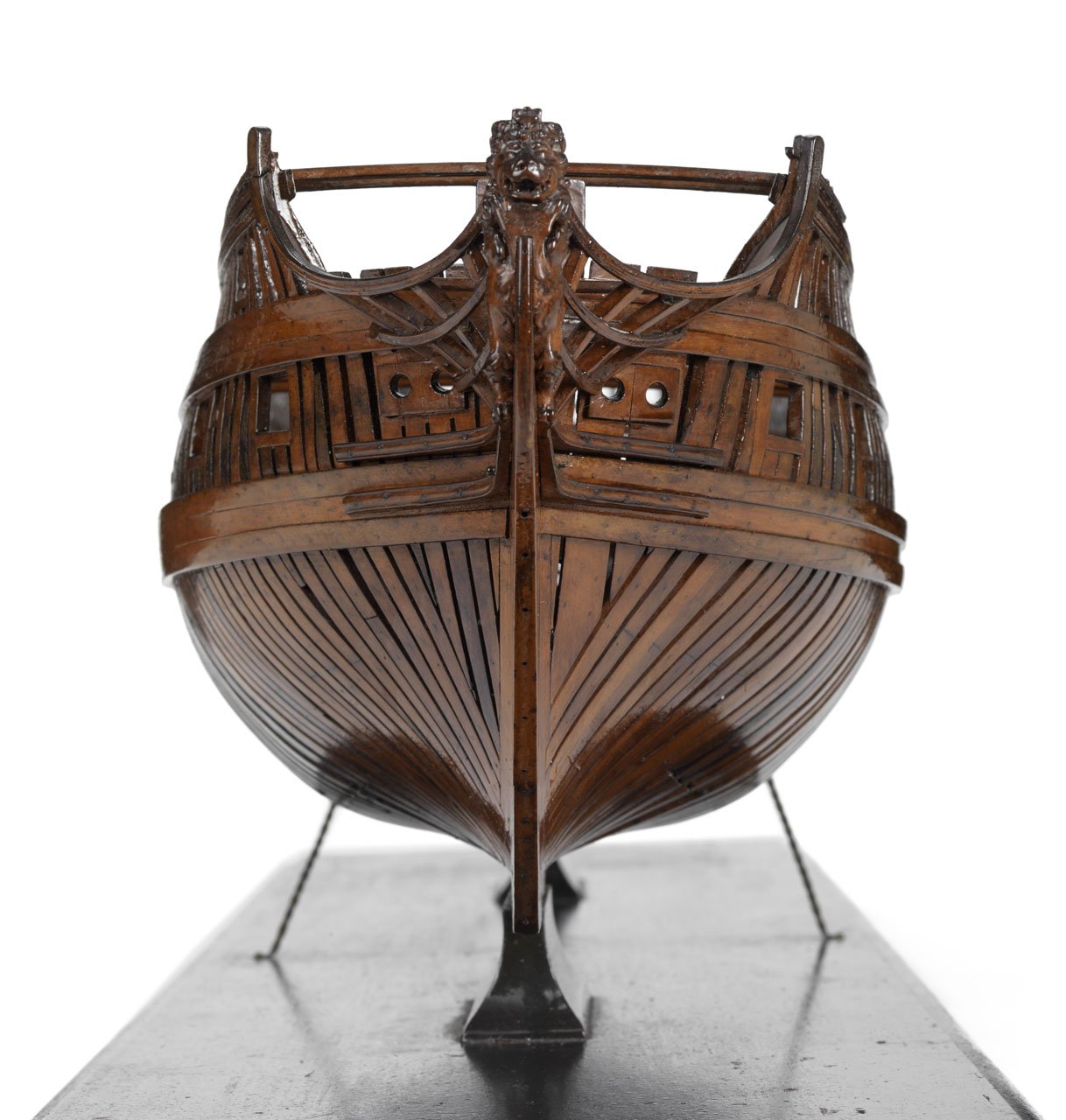
Thanks Druxey, Richard, The model was built circa 1715, shortly after cant framing came into use. The model was built to show the differences as far as anyone knows. Anderson gives some good detail on the model in his book Navy Board Ship Models and RMG has photos and some information in there "Collections" which follows: Scale: 1:48. A contemporary full hull model of a 50-gun small two-decker (circa 1715), built entirely in frame. It has been built to show the old style of construction against the new, especially around the area of the bow and stern. The wales are solid or ‘closed’ on starboard side and ‘open’ in two strips on port side. Although the framing configuration differs markedly on port and starboard sides, it has the dimensions as laid down for the 50 gun ships of the 1706 Establishment, but the closed or solid wales would suggest a later date of 1717. An important feature of this model is that it shows the hull framed up as built as opposed to the more stylized Navy Board hull framing. Allan -
Hawse holes
allanyed posted a topic in Building, Framing, Planking and plating a ships hull and deck
In looking at contemporary model photos, a question came to mind for me. As a rule, were the hawse holes cut so to be parallel with the keel, or at a specific angle (90 degrees??) to the face of the hawse pieces and boxing? The following is a photo of the bow of the 1715 model of a fifty gun ship that is framed port with square frames and starboard with cant frames. In each case, the hawse holes are clearly not parallel to the keel but was this the norm? Allan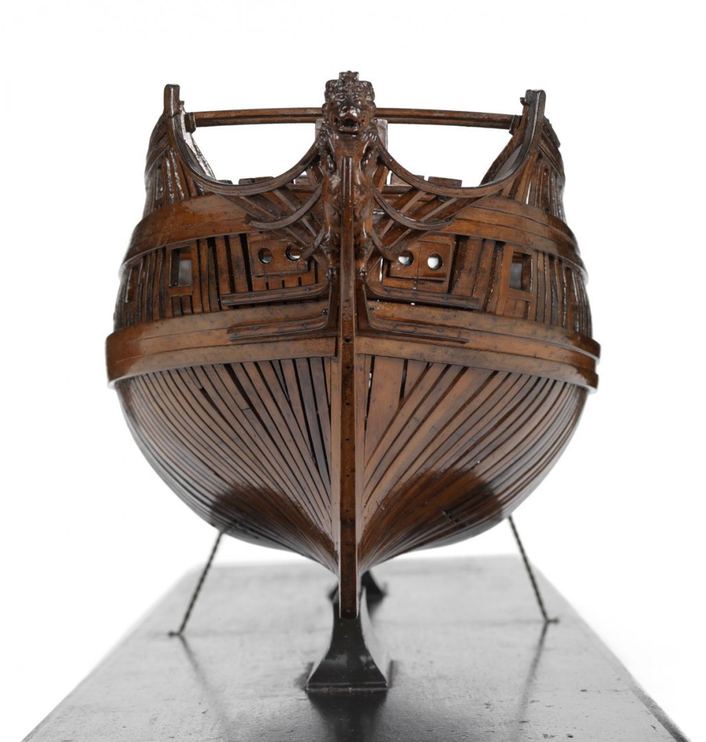
-
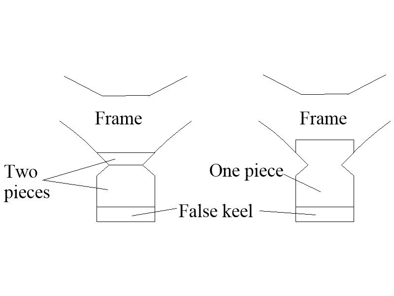
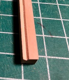
I have always cut the rabbet into the keel until my current project in which I indeed did a "doubling" . The reason for the change is that for the time period for this model which is the late 17th century and the rabbet starts at the top of the keel with no shoulder. The frames sit on top of the keel with no notch. Cutting the rabbet was problematic for me in that it was nigh impossible to maintain the top part of the rabbet at exactly the top of the keel without disturbing the top of the keel itself. As it turns out, it was also easier to form the angles of the top and bottom face of the rabbet along the keel as it is dynamic along its entire length. There is a seam of course, but as it is at the juncture of the two faces of the rabbet, it is not noticeable. Allan
-
Rich, Per the above responses, the photo has a ton of errors. I personally would not use the photo as a guide at all. From what I can see, not only are many lines rigged improperly, it appears in some cases that they are different port and starboard, including the spritsail braces. The written description for the braces for the spritsail yard may be correct for a US ship such as Rattlesnake, but if it were to be the same as for British ships at that time it would be rigged differently. For the British, the standing part of each brace was seized to the yard just inside the lifts from about 1700 to 1719 but the rest of the rigging of the braces was complicated. At that time the running part ran up from the yard and through a block seized to a short span about half way up the forestay. It then went down and through the brace pendant block at the yardarm. It then ran up to another block on a short span about 2/3 up the stay, then through a block under the forward part of the foretop. It then ran aft and through another block at the aft part under the top, then through a block on a short span on the mainstay, then down to a cleat on the bulwark aft of the of the forecastle bulkhead. Before and after those dates, the standing part for each brace was seized to the forestay, not the yard. From 1760 to 1815, it was seized about 3/4 of the way up the stay. Each then rove through a brace pendant block and then went up and through a block under the foretop, then down to the deck. I totallyh agree with John about getting a copy of Lees. Petersson's is well done for one type of ship in one specific time frame but not necessarily useful for other vessels or time periods. Allan
-
Ken, Your post sparked a bit of a search for me which for me is as much fun as the building itself Wefalck is correct that carronades came into use later. According to Adrian Caruana in volume II of The History of English Sea Ordinance (pp.161-162) several folks are mentioned as the inventor but General Robert Melville claimed to have the idea in 1754. But, he was not in a position to approach a gun foundry until 1774 when he went to the Carron Company. Charles Gascoigne, a partner at Carron is given credit for leading in the development of the carronade. The first actual use was in 1778 so there would not be any carronades in 1760. She may have been refitted with them after 1778, but she would be well aged by then so there may be some doubt that these would be found on her at any time. Hopefully someone here can corroborate this but I doubt that carronades were ever made of brass and the shot weight was likely more than 9 pounds. Fifth rate frigates (32-44 guns) would likely carry a least 18 pounders and the smallest frigates, sixth rates (20-28 guns), and sloops (16-18 guns) would carry 12 pounders. Originally 12 pounders were 20 inches long and 18 pounders 24 inches long. In 1780 they were 26 inches and 28 inches long, then by 1798 they were 33 inches and 40 inches long respectively then reduced in length in 1815. In my looking on line and in a few books, unfortunately I could not find any British built frigate named President in the 1700s or 1800s so I wonder if this is a fictional ship. Sorry for droning on but I do hope some of this information is of help. If you do go with the carronades, and the barrels in the kit are brass, you can always blacken them so as to represent them as iron rather than brass. Allan
-
Hi Allen Welcome aboard, and thank you very much for sharing a little about yourself! You have a huge number of teammates here ready and willing to help. Allan
-
I am pretty sure hide glue is not useful for plastic, and considering this is for use by retired folks in assisted living, it is probably not appropriate even for wood unless they have a shop, melting pot, &c. Just my take on this specific situation as I envision a meeting room with few if any shop amenities. Allan
-
Rob, Yes, the booms are secured as described by Jason, but I don't know where the stunsail yards were stowed when not in use. Great question. Allan
-
Assuming you are going to order on line or perhaps venture out to a Home Depot or Lowes or such, stay simple. Avoid CA (Super Glue) glues as the fumes are noxious and the elderly folks unfamiliar with it may have mishaps gluing their fingers to the model or each other. For plastic, good old plastic model glue like Testors Plastic Model Glue TES3501 or similar. Found in hobby shops, on line, etc. For wood, any brand carpenters glue. Titebond Aliphatic Glue (commonly called carpenter's yellow glue,) or Elmers Carpenters Wood glue are great choices and easily found on line or in any builder's store. Hope they have fun with these!! Allan
-
Hi Malas What Dave said above for sure, very good advice! . Which ship are you rigging? You mention tie rigging to the top of the masts but in addition to which masts, to which lines are you referring, back stays, stays, shrouds, or something else? Photos would help get you some good responses from the crew here at MSW. Allan
-
There are five items for each yard that takes a stunsail, , the yard itself, the studdingsail boom port, studdingsail yard port, studdingsail boom starboard, and studdingsail yard starboard. You can see these on the drawing on page 105 of your Diana book.. The booms slide outboard through guide rings attached to the yards. The studdingsail yards "hang" free. For the lower yards stunsails, the stunsail yard has a halyard seized around the stunsail yard and roves through a block seized to the outer boom iron on the foreyard. There are also inner halyards and sheets for each stunsail. There are very detailed drawings in Darcy Lever's Young Sea Officer's Sheet Anchor which is also reproduced in Lees' Masting and Rigging on page 116. In this case, the drawings truly are worth a thousand words, maybe more. Allan
-
Scale bright work
allanyed replied to Kurt Johnson's topic in Painting, finishing and weathering products and techniques
Kurt, For the next time, Swiss/steamed pear is fantastic to work with, has a beautiful reddish color, is very close grained, carves beautifully, and takes all types of finish coatings well. No stain needed!!! Allan -
What size single block is needed for 1:250 scale ship?
allanyed replied to bogeygolpher's topic in Masting, rigging and sails
Bogey Golfer - Hope you are as lucky as us and your favorite course is open. Do you have Lloyd McCaffery's book Ships in Miniature? He typically builds at 1:192 and smaller and has a TON of tricks and methods for the rigging, including the lines as well as blocks and deadeyes. In short he uses punches of various diameters to punch blocks and deadeyes from Bristol board in various thicknesses. Lloyd's work is incredible, right down to making assembled gratings at scales to 1:384. Anyone building a model smaller than 1:100 would be well served to have this book on their shelf. Allan -
Roger, Your description is very clear but alas, the photo is out of focus and can barely make out the boat. I am curious to see your deck results and kindly ask if you can post a closeup photo. Thank you very much. Allan
-
Wahka 0.5mm would be about a 1 inch wide seam if 1:48 scale and 2 inch if 1:96 which would be way over scaled. Even card stock (~0.3mm) is too thick in most cases. Paper as PR suggests is better. For smallest scales, marker or black tissue paper found in craft stores works very well. Apply as described above. Allan