allanyed
-
Posts
8,149 -
Joined
-
Last visited
Content Type
Profiles
Forums
Gallery
Events
Everything posted by allanyed
-

Curved deck
allanyed replied to Slok9000's topic in Building, Framing, Planking and plating a ships hull and deck
Hi Slok You do need to hold it down so it curves. Normally it will curve fore and aft as well as to match the rounding of the frames (bulkheads in this case) athwartships. If the initial decking is a piece of thin plywood and will get individual planks on top of this sheeting, pins are fine. When doing individual planks, you can just hold them in place for a minute or less with your finger using carpenters' glue and they will stay down in place. Welcome to this motley crew of ours. Allan- 1 reply
-
- 2
-

-
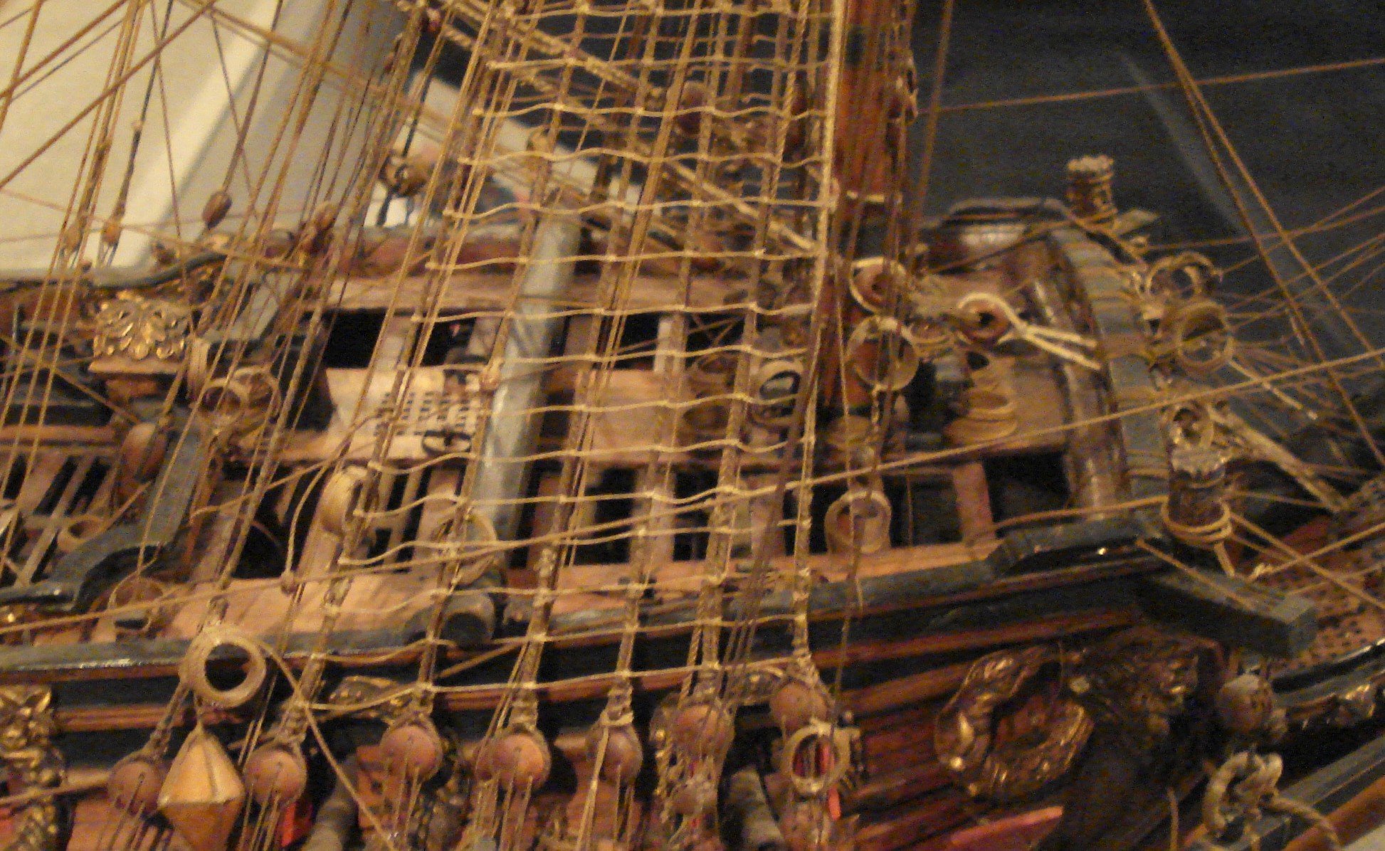
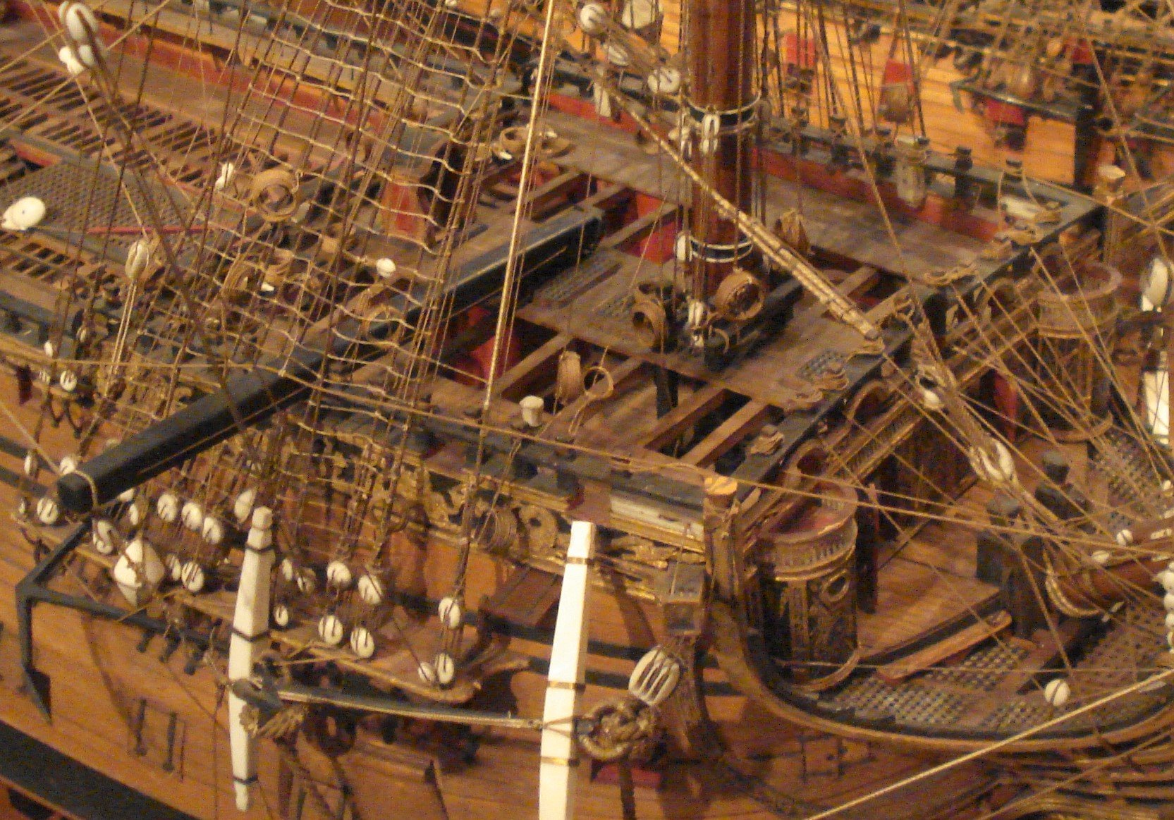
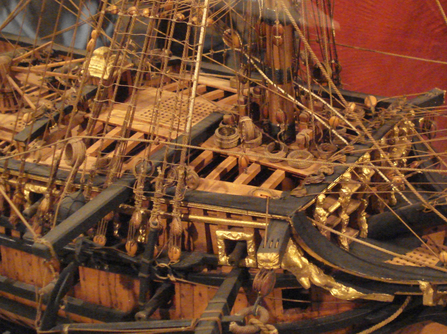
Thanks Druxey. Actually I am looking at rigged models. Several examples follow. The specific time period I am interested in is mid/late 17th to early 18th century. The following are a fourth rate of 1705, Grafton 1679, Royal William 1719, and a 3rd rate 1650. All models are at Preble Hall. Thanks again.

-
Thanks Mark and for the added information Druxey. My concern is that there are no English contemporary models that I can find for the 17th century or very early 18th century using belaying pins and as accurate as they usually are, I am surprised this is the case if belaying pins usage was the norm. Thanks again, this is definitely enlightening information. Allan
-
Great find Mark. Based on Mainwaring's dictionary, pins are stated to have been in existence as you point out, but was this common practice? Based on contemporary models of English ships of the early 18th century or earlier I do not recall ever seeing them present. The models and photos of models that I have seen invariably show such running rigging belayed to timber heads and cleats. From the standpoint of rigging a model, I would prefer belaying pins but I am not so sure this would have been the norm in the 17th or first half of the 18th century. Allan
-
gun ports
allanyed replied to Anthony Hearne's topic in Building, Framing, Planking and plating a ships hull and deck
Hi Pat I know very little of this vessel but I believe she was equipped with sweeps so would the main purpose of the small ports be for the use of the sweeps rather than the comfort of the crew? Allan -
Boxing joint or scarph
allanyed replied to allanyed's topic in Building, Framing, Planking and plating a ships hull and deck
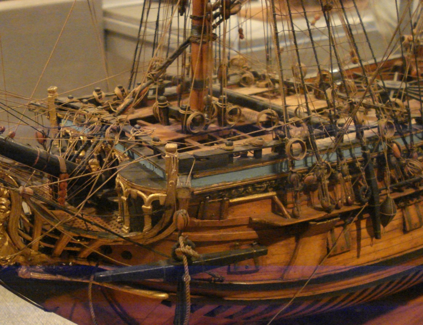
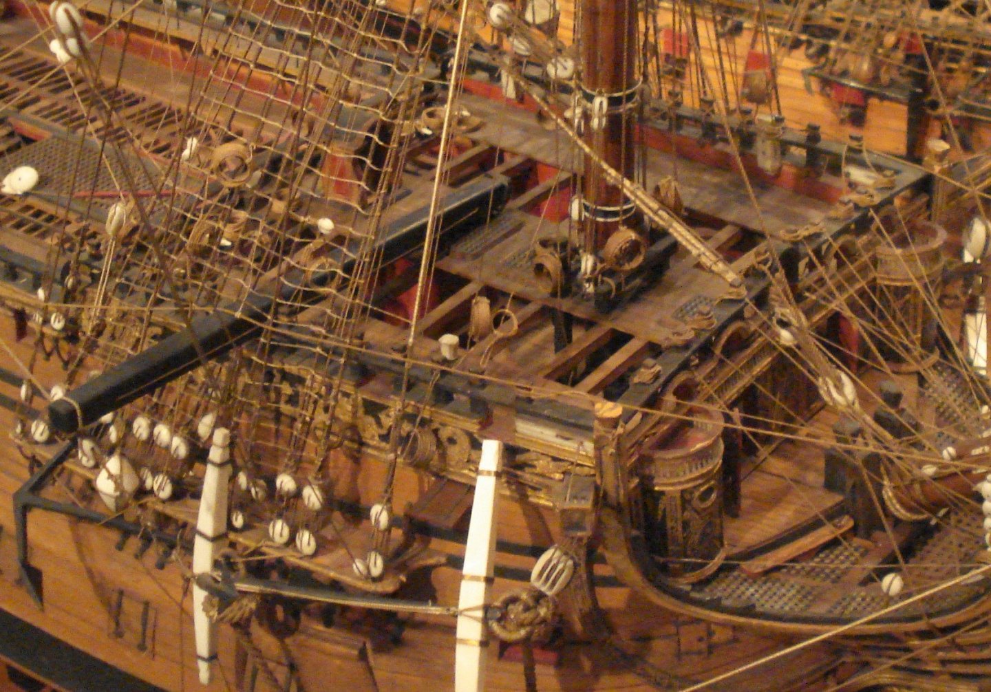
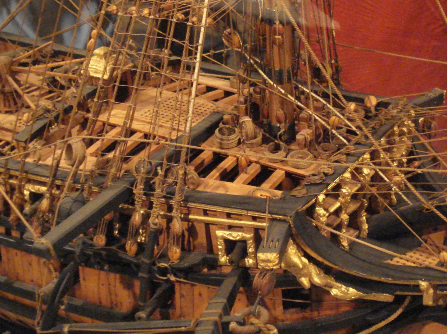
Thanks Druxey. By the same token, why would the model makers use a stylized type of framing rather than full framing? Based on the information I have been able to dig up I really think either a vertical scarph or boxing joint could be correct but will err on the side of caution and go with a boxing joint as you are betting :>) Allan -
Boxing joint or scarph
allanyed replied to allanyed's topic in Building, Framing, Planking and plating a ships hull and deck
Thank you very much. I looked at the drawings in Franklin and he does show what surely looks to be a boxing joint from the model of Bredah., even though he calls it a short plain scarph I was surprised to see the 5 additional types of scarph joints found on contemporary models and should have seen these before. Big oops on my part :<( But, would any or all of these be typical of the joints used on the actual ships as well, not just ship models? This chapter shows frame construction etc. for admiralty models which is nothing like actual shipyard practice so I would not be surprised if these joints are not to be necessarily found in the actual ship construction. Barring any other insights, I agree, I will not be amiss in using a boxing joint. Thanks again. Allan -
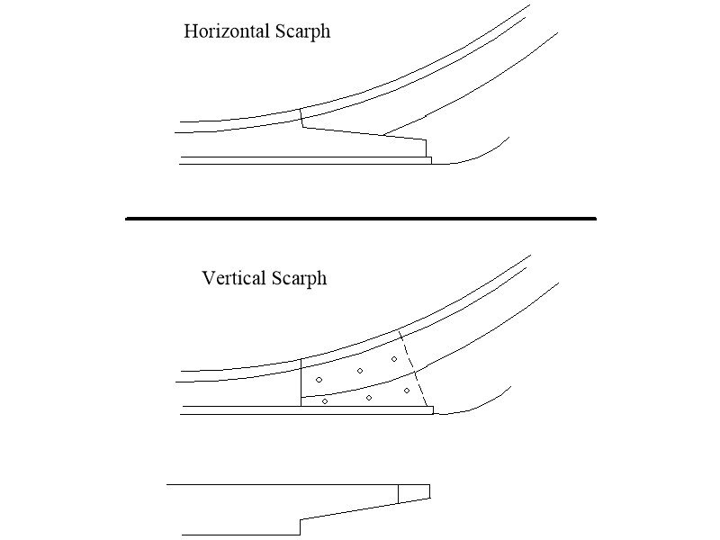
I have not been able to find any information on when boxing joints at the keel/stem junction came into use, so not sure if a boxing joint, or more likely, a scarph is appropriate for a 50 gun ship, 1695. The following from a contract for two 50 gun ships of 1695 mentions scarphs for the keel, but nothing regarding a boxing joint. Keeles to be of Elme (Not More than in Three Pieces) and to be fourteen Inches Square in the Midships with Scarphs Four Foot Four Inches Long at least and Each Scarph Tabled and laid with Tarr & Hair, to be well bolted with Six Bolts by an Inch Auger. Assuming a scarph is appropriate, would it be a horizontal scarph or a vertical scarph as found along the rest of the keel. Goodwin describes boxing joints and a horizontal scarph, but nothing regarding a vertical scarph at the junction of the keel and stem. I would be grateful if anyone can confirm if one of the below or some alternative is correct. Allan
-
I still prefer to print (or make a copy) onto full sheet size (8.5X11) label paper and then cut out the individual parts on the paper, peel off the backing and apply it to the wood. No stretching or distortion and easy to scrape and sand the paper off the wood once the piece is done. Avery brand is good by pricey. Store brand from Staples in the US is much less expensive. Allan
-
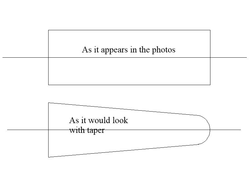
Yes, the rounding on the sketch is exaggerated. It was likely squared off but with a radius, not a sharp edge. The scantlings for a 50 gun ship in Steel's Elements of Naval Architecture shows the knee to be sided 1' 3" at the stem at the upper end and is sided at the fore part at the upper end 5" , quite a bit of taper. Not sure if this would be exact for Leopard as she was 30 years prior to the Steel Scantlings being published but surely a taper would be appropriate. This taper is also described in the Swan series Fully Framed Model Volume I and Euryalus, Volume I. Allan
-
Hi Tom My apologies for jumping in so late in the game, but there is one thing that you may want to look at modifying. I only point this out as I made the same mistake on a model some years ago and was sorry I did not make the change. The knee of the head looks quite wide at the top forward portion. It should taper moving forward down to about 6 inches or so, where the figure head will sit. Where the pieces fit to the stem, they do widen as they rise as you show, but the top pieces should then taper a lot as they go forward. Maybe a difficult fix at this stage, but something to consider. As I had not made this change on my old model, the figure head looked bow legged. Again, my apologies for bringing this up now, I hope you don't mind. Allan
-
Greg, I have successfully used Sparex as well for a number of years but without heat which I will try going down the road. Definitely a better way to go than acetone or other solvents that I had tried prior to using the Sparex. Do you have any idea what temperature the crock pot gives you? I was thinking it might be as easy to heat some water, dissolve the Sparex and put the pieces in the solution. Thanks for the description, very well done and extremely useful. Allan
-
Mark T, thank you for your quick comment. Mark P. Great information in total. Severn and Burlington are part of the 130 foot group of 50s which includes Litchfield so quite valuable information for me. Thanks Bob, also super information, thank you for your response. Allan
-
Mary, If a ship was fitted with sweep ports, there are hinged covers to keep any water from splashing in when not in use. If the sweeps are deployed, it would be most likely be due to the ship being becalmed so no worries for water coming in those conditions. I see this as your first post. Welcome to MSW! Allan
-
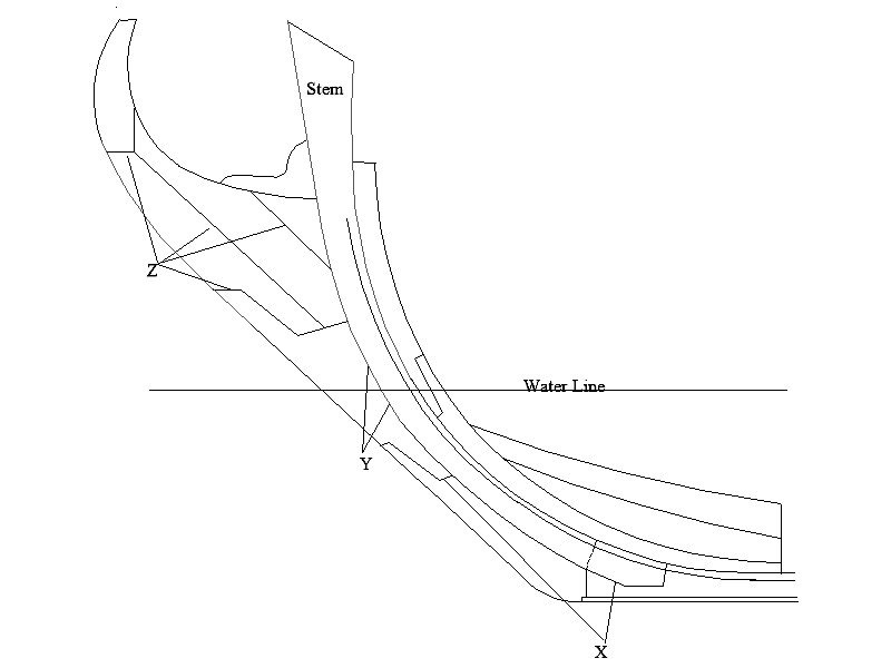
Sorry for any confusion. I was only referring to the seams at joints of various pieces such as the keel scarphs and boxing joint, not coating the entire hull below the water line which I believe would have been with "White Stuff" prior to coppering. In the drawing below of for Litchfield (1695) the joint at "X" would be coated. I assume the lines "Z" would have no need for the coating thus would not be done, but would Y be lined with flannel and tar from bottom to top. Below the arbitrary waterline I have drawn, it should be lined, but would it continue to the top? Thanx, Allan
-
I cannot find anything contemporary and truly definitive on where in the construction of British warships the practice of "waterproofing" with tar and flannel took place. My understanding is that it would be outboard and below the water line, for the most part. This would include the boxing joint and at least the nib ends of the keel scarphs for example. I assume this would not be done on the stern post and inner post as the joint for these two pieces were inboard of the hull planking. For the stem area, it makes sense that this practice would be used at and below the waterline, but did it continue upwards on the seams where parts of the stem area were joined together and continued above the water line? This may be a pretty basic item but In the words of Albert Einstein, "I have no special talents, I am only passionately curious." Allan
-
So, no names would be appropriate before 1771 or after 1781. Guess the best way to identify a model of a British warship that we build from before and after those dates is a nice plaque on the display stand to keep things accurate. Thanks to both of you for the information, a new one for a lot of us I suspect. Allan
-
Druxey, very interesting comment. Any sources and/or dates that you know of on when names being painted (on the stern) came into (and/or went out of) fashion. I stopped using raising lettering in wood letters many years ago as I learned (I think from you) that this was not done, at least on English vessels, but did not know there was a period when no names would have been painted. Thanks! Allan
-
Very well done book report Mark. Time to add on to the library. Thanks for sharing. Allan
-
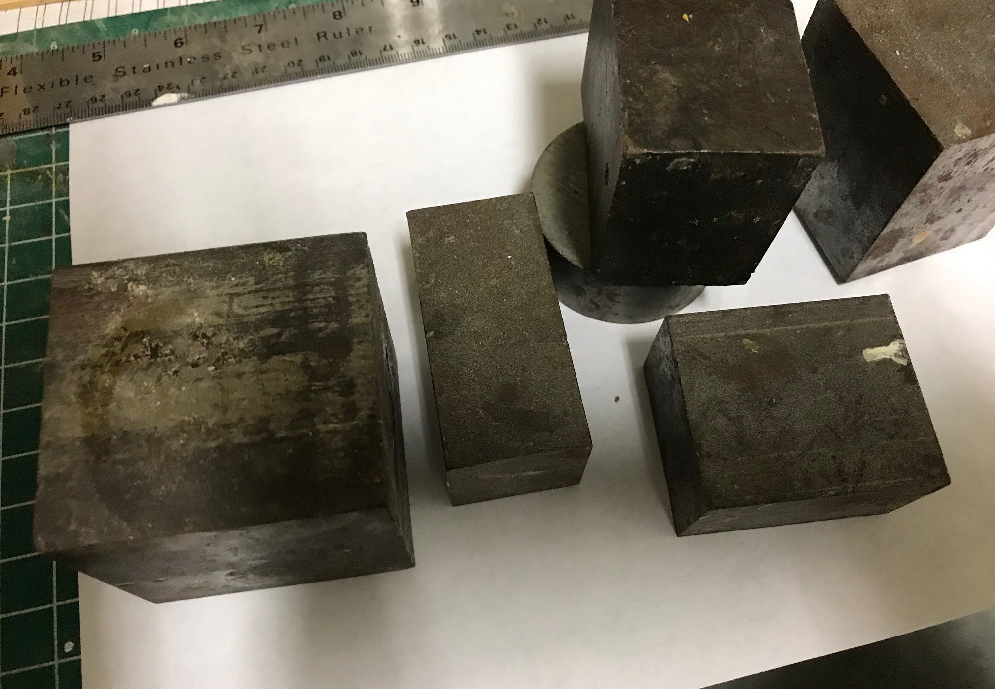
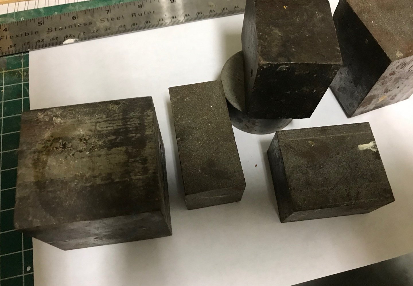
Shortgrass, I feel your pain. Clamps are a good way to go but there will be a point where there is no where to get a clamp in place. I have 7 our 8 scrap pieces of steel blocks that I use to hold things down when necessary. Put a piece of scrap wood between the steel and the part to be weighed down to avoid putting dents in the wood. I picked these up from a small machine shop that had a barrel of scrap and they were happy to give them to me for free. Allan
-
I normally use Castello boxwood for hull planking on warships and such, but for the few schooners that I have built for clients I have used poplar if the hull is to be painted. It sands well and with a coat of primer, takes paint and then four or five coats of sprayed urethane top coat with no problems. If it is not to be painted, you may want to also consider basswood. Chuck Passaro has shown that it can give a very good looking finish and there is no issue with the color variations found with poplar. You can get basswood on line through dealers directly or via Amazon in blocks up to 12 inches long or sheets up to 24 inches long. Allan
-
The whole group here, including yours truly are thinking positive thoughts for you and wishing you the best!! Allan
-
Bruce, For the carronade itself, the length given by Caruana in Volume II of The History of English Sea Ordinance for a 12 pounder is 33" long as of 1798, then 26" long as of 1815 so the 33" would be right for the time period you give. This may be OK then to use to scale a drawing of the carriage itself as you mention. Your description of the carriage brings up some questions. When you say wheels (trucks) do you mean in line or traversing? most carronades had only two traversing trucks, but even when four trucks were present, most of the time they were all traversing trucks. The four wheel trucks may not have come into use until about 1815 from what I can find in Caruana's Sea Ordinance book. Again, two traversing trucks seemed to be the standard. There are examples where larger trucks that were parallel with the long axis of the carronade were sometimes used similar to long guns but these were used on the poop of larger ships starting about 1808. To complicate things even more, these also had traversing trucks at the hind in-line trucks so had 6 wheels. There is a drawing (side view only) of a four traversing truck carriage on page 204 of Volume 2 of Caruana's Sea Ordinance book. There is also a drawing of modified carronade non-recoil carriage that had four in line trucks added to 24 pounders that were tested on the Wolverine about 1802. All of these are for joint mounted carronades as trunnion mounted seems to have stopped being made by about 1790. PM me if you would like a drawing of a 2 traversing truck carriage I can scale for you if you want to go this route. Allan
-
Deck planking plans
allanyed replied to KingDavid's topic in Building, Framing, Planking and plating a ships hull and deck
David, I am sure you realize the dimensions I gave are actual size, not scaled. Not knowing the scale of your model, I don't know the sizes that you would actually be using. Gregory gave you a conversion set to use for , but first you need to convert 10" (for example) to the scale you are using. If 1:48, it would be 10/48 = 0.208". 0.208 inches X 25.4mm/inch=5.28mm wide planks. Planks from 5 to about 6mm would be pretty much to scale for a 1"48 scale model. NOTE: I misspoke earlier. The water way would likely be about 11" to 12" wide. The planks of the flat would be closer to 9" or perhaps 10" wide. Allan -
Deck planking plans
allanyed replied to KingDavid's topic in Building, Framing, Planking and plating a ships hull and deck
David, Planking for the upper decks and quarter decks for all vessel sizes shown in The Ship Builder's Repository 1788 and Steel's Elements of Naval Architecture show planking thickness of 3" with one exception for a small sloop with 2 1/2" thick planks on the QD. Based on the photo of the model of Lady Nelson 1799 at the RMG (below) with a single deck from bow to stern, and a length of a little over 50 feet, I suspect there could be as few as 2 pieces or perhaps 3 per strake. With three it will be easier to have the butts in a 3 or 4 plank shift and still have lengths that would be reasonable in full size work. Of course breaks would occur at the hatches and other openings for masts &c. Considering the time frame, there is likely a waterway and may have at least the forward ends of the strakes of the flat joggled into the waterway. If there is a water way, the outboard edge would be an inch thicker than the inboard edge. Width of the water way should be in the neighborhood of 10" or 11" and the strakes of the flat should be about 8 or 9 inches wide. Hope this is at least a little help to you. There are likely others here with more knowledge on this type of craft. Allan