allanyed
-
Posts
8,149 -
Joined
-
Last visited
Content Type
Profiles
Forums
Gallery
Events
Everything posted by allanyed
-
 Totally agree with Phil that it is great. I did a little digging and plywood is an interesting thing. Aircraft ply has the most stringent criteria in manufacturing for plywoods. A description from Wicks Aircraft ---> it is made with thermosetting, synthetic resin type glues. Geniune aircraft plywood meets MIL-P-6070B which requires that the plywood be tested for general condition of boards, deviations of thickness, moisture content, tensile strength of wood, gluing strength, bending test, torsion test, immersion test and boiling test. (The boiling test is three hours!) No voids (filled or otherwise) are permitted as is allowed in cabinet grade that is found in the big hardware/lumber stores. https://www.wicksaircraft.com/c/aircraft-plywood/ They have larger sheets and the prices looks competitive, especially for the thinnest stock. Allan
 -
There are four APA grades of plywood, A, B, C, and D. A is best but it is not cheap. Allan
-
Hi Ross, I don't think you are misreading the plans, the plans look to be incorrect. There is a great description in your Lees book (congrats on getting a copy!!) on pages 2 to 4. Thanks for the compliment when you wrote You have forgotten more about ships than I will ever know, it was a very nice thing to say. Trust me Ross, I am no expert compared to many members here and I do forget things from terminology to methods all the time. I just have been fortunate to have accumulated a good library of books, plans, and contracts over the years and use them as references all the time. Regarding forgetting things, in general it's part of life and in the words of Bette Davis: 😀 Allan

-
Sizzolo, do the plans call for top and butt planking as you show (or anchor stock if I am seeing it wrong in the photo) Either way it is SUPER that you included it, and impressive if the kit did show it in the instructions. WELL DONE!! Allan
-
Hi Ross, Live and learn, this is a new one for me. Which lines would have a block attached to the wooldings? I realize this may not apply to ships other than those of the RN, but based on James Lees', The Masting and Rigging English Ships of War, there were always wooden bands nailed to the mast on the top and bottom of rope wooldings so they could not slip on the mast. This makes sense for any nation. I cannot picture how a block can be rigged to these with them enclosed inside the wooden rings. Thanks Allan
-
Clever way to have the risers (thwart support strips) in the right location. This one I want to remember. Thanks for sharing. Allan
- 20 replies
-
- 2
-

-
- 24 ft Launch
- Vanguard Models
- (and 1 more)
-
Welcome to MSW. Allan
-
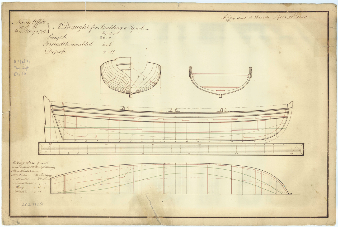
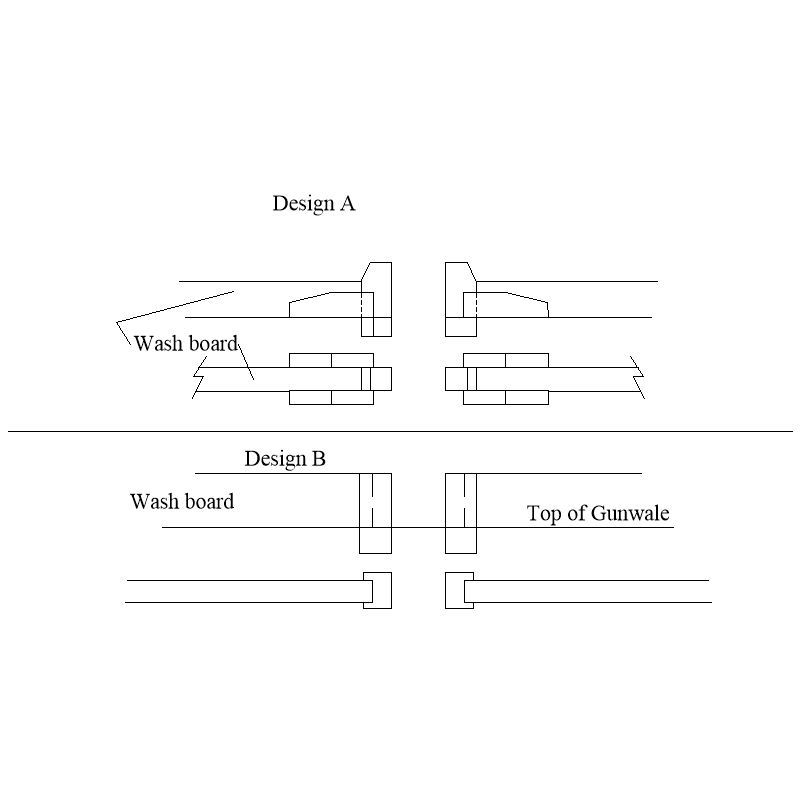
It sounds like you are speaking of washboards. Thole pins were common on long boats but the later boats SEEM to have the cutouts as Keith shows or the style as shown below. Note that in this particular plan there are six thwarts and three spots for the oars as is single banked. There has been some question as to whether the launch for Bounty was single banked or double banked. Allan
- 32 replies
-
- 2
-

-
-
- Bounty Jolly Boat
- Artesania Latina
- (and 1 more)
-
Welcome to MSW Carter!! Hope to see some of your work soon. Allan
-
Maybe I should start a new thread but this is in keeping with the overall subject. What did Spanish naval long gun carriages look like in 1620? I have done a couple hours of research and have found very little hard information. I am leaning towards truck carriages with two trucks even though a lot of modern models show four trucks. One source that is interesting is a video https://www.youtube.com/watch?v=loldlSJ4k_8 There are about 25 seconds of WWII film, then the good stuff. If anyone has any details they can share on the carriages for various size Spanish cannon in the early 17th century based on contemporary sources I would be grateful. Allan
-
Happy holidays Richard! If you use copper instead of brass, a little diluted liver of sulfur can be done off the model, or on, as it does not stain the wood and is instantaneous if the metal is clean. Biggest problem is that some do not bother to clean the metal first so there are problems. A little time in an acid bath followed by a water rinse, or even a soak in acetone to get off any oils from touching the parts works wonders. Allan
- 36 replies
-
- 1
-
-
- Shallop
- Pavel Nitikin
- (and 1 more)
-
Hi Kenny I just looked at over forty high res contemporary plans of all types of English boats and only three showed cross sections that showed the keelson and only one had the footwaling. The one with footwaling showed no spaces, just a line of where the outboard edges ended so it is anybody's guess what the space was. between each strake. The thickness and width of the keelson is found in scantlings and contracts but so far I have only found the thickness of the footwaling. Like many things on board, common sense probably comes into play. A gap small enough to prevent the rowers' feet from getting stuck between the footwaling would likely make the most sense. I think, an inch, maybe two would be ideal. Then again, maybe some member has information based on contemporary sources that give more details. I realize it is not a long boat, but I thought you might find the following transcription of a contract for a pinnace and a yawl interesting. Spelling is as on the original contract. Allan Contracted the 9th of 7ber [September ] 90 with the Honoble Tho[mas] Willshaw, Esqre one of the Principall Officers & Commrs of their Majties Navy, for and behalf of their Maties, by me Tho[mas] Oxford of Gosport Shipwright and I doe hereby oblige my self to deliver into their Majties Stores at Portsmouth, by ye end of 8ber [October] next ensueing the Pinnace and Yawle undermentioned of the Dimensions and Scantlings folling (viz) Long Broad Deep Pinnace of 30ft: ----- 6ft: ------ 2ft: 7ins ------- One Depth of the Keel: 5 ins breadth 4 ins, Scantlings of the timbers 1 ½ ins Roome and space 13 ins, depth of the Gunwales up & down 4½: ins in and out 2 ins & 1½ in, Scarph of ye Timber 18 ins, breadth of ye Stem thwartships 3½ ins fore and aft 7 ins, Stern post 3ins, Rising 4½ in, footwales broad 4½ ins and one inch thick, Keelson 8 ins X 1½ in thick, to be fitted with 12 Iron Knees 5 bound thwarts wth Iron Knees & two Transom Knees, with gang boards) and Scarr boards [Wash boards?], benches three lynings, Grounds & mouldings, plankshires turn[e]d off, back board one, bottome boards two, Keel band 22 ft Ring bolts two, Rother iron two paire, Rother one once primed at the Rate of fourteen shillings per foot. Yawle of Long Broad Deep ft ft 23 ft 5 7 ins 2 5 ins One Railes for the upper strake to be made out of ye whole wood up & down Gunwales stuck, 3 thaurts bound with Iron knees, & ye transoms with two Iron knees. The State Room (stern sheets, or officers’ seating area) stuck (presumably meaning ‘struck’) with an O:G. & plansheer for the Gunnwales with pannels on each side the back board, a locker under the after bench & lynings under the benches, keel thwart shipps 4 ins up and downe, 4 ½ ins X 4 ins Keelson 6 ins broad of 1 ½ ins planck timbers of 1 ½ ins with 13 ins roome and space and 18 ins Scarph, the flower [floor] timber heads to Naile to ye lower edge of ye binding strake, with bottom boards, & shear boards, Keelbands and Iron bolts and Rings for stem and stern, to row with six Oars to be graved and primed to the water line and paid with stuff in the inside to ye Riseing att 12s per foot
- 50 replies
-
- 1
-
-
- 18th century longboat
- model shipways
- (and 1 more)
-
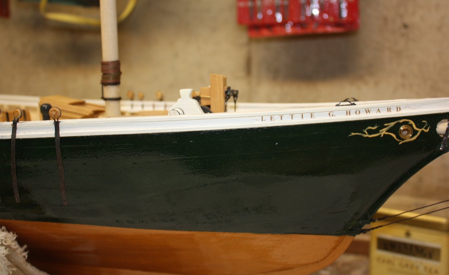
Thank you very much for the link Cap. From what I read on the Mystic site Elsie was 124 feet so scantlings may be quite different than the L. A. Dunton. I think the Ernestina may be closer regarding scantlings. Either way, both are great sources and I have not yet built either Elsie or Dunton so fun awaits. Personally I would lean towards the latter as it has not been done to death like Bluenose and Elsie. I envy you as you are so fortunate to have had such a great opportunity. Hope you saved some of the scrap wood and incorporate it into your model. I did that with a piece of keel I pulled from a scrap heap in St. Michaels where they were rebuilding skipjacks and used it for a little of the planking and the keel. Allan
-
drilling hole through wire
allanyed replied to BETAQDAVE's topic in Metal Work, Soldering and Metal Fittings
A milling machine is the only way I have been able to do this kind of operation with a high degree of success. If it is as small as yours I chuck the bit with about a mm protruding from the chuck so it will not flex. If the hole needs to be deeper, I at least get the center mark where it should be then can bring the bit out further. I love my Sherline, so a good choice based on my own experience, limited as it is. I know that you know, but for others that may not have had the experience, HIGH quality bits are a must. Allan -
Funniest thing I have heard in a while😀 Members sometimes disagree with each other over points here and there, but we all love this hobby and I for one am very happy to learn from every single member and/or be corrected if I got something wrong. Going back 50+ years ago I was taught by one of my first bosses that even the newest member of our team can often do something better than anyone else and as a supervisor it was my job to find out what that was and utilize that skill for the betterment of all of us. Same goes for this hobby. Many of us have decades of experience but we often learn a new trick or idea from even the novices thanks to our membership's willingness to help each other. But I digress.....
-
Looking really good! Question, hope that is OK. Did the kit give instructions for such a large gap between the keelson and four strakes of footwaling? Seems like a rower could get his foot stuck between these. I don't know the width of the model so hard to scale this gap, but if the breadth is about 9' ( 2.25" at scale) the gap looks to be around 4" (0.08"). I think the gap would be no more than what the openings on a grating would be, about 2.5" Even so, your model looks super and the workmanship is neatly done. Probably just a terminology thing, but I do not see any of the rails that you mention. You might find the attached useful for future boat builds. These boat scantlings can be found in Scantlings of the Royal Navy which are a transcription of scantlings given in W.E. May's book The Boats of Men of War, Again, very neatly done work, kudos!! AllanBoat Scantlings 1-28-14.pdf
- 50 replies
-
- 1
-
-
- 18th century longboat
- model shipways
- (and 1 more)
-
Who uses nails?
allanyed replied to bigcreekdad's topic in Building, Framing, Planking and plating a ships hull and deck
This is less than 2" full scale at 1:48 so sounds spot on. Do you know if there are smaller screws? For smaller scales such as 1:64 that will leave a hole way over scale. Are the screws you are using wood screws or?? Can you post a pic, this sounds like a solution for many builders? Sorry for all the questions😕 Thanks Vaddoc! Allan -
Are these available for sale from Mystic or can they be found elsewhere. The photos you posted are fantastic and the plans look really good. Would love to get a set into my own archives for the next schooner project. IF you are thinking of building a model of her, while it is a huge pain in the neck to use, Chapelle's American Fishing Schooners should be very useful. Bluenose (1921) and L.A. Dunton (1923) are contemporaries in time so you are probably right that contemporary information on Bluenose might be very useful. The scantlings may be quite different as the lengths that I could find appear to be very different at 104 feet and 143 feet. The Ernestina (nee Effie M. Morrisey) may be more useful as she was 112 feet and there are very detailed drawings and photos in the Library of Congress downloadable for free. https://www.loc.gov/resource/hhh.ma1719.sheet?st=gallery and https://www.loc.gov/resource/hhh.ma1719.photos?st=gallery Allan
-
It takes most builders years to reach higher and higher skill levels, but as it is an ongoing process I do not understand why these would be separate goals? Is there an example where we would choose a subject we like but are then unable to use this choice to start or continue to develop modeling skills as well? Inquiring minds and so on😀 Allan
-
Who uses nails?
allanyed replied to bigcreekdad's topic in Building, Framing, Planking and plating a ships hull and deck
Assuming you plan to leave the nails in place, the use of metal fastenings depends on the ship/nation/era. Scale also matters. I am pretty sure treenails made of wood were more common than metal fasteners in the age of sail but at scales smaller than about 1:48, even wooden treenails tend to look oversized. On the real ships, they were near invisible. There are a number of beautiful French models by Bernard Frolich where he used brass nails but only AFTER the planks are glued in place. He is explicit that the heads must all be filed off which is no easy task. If there are not, they will be totally out of scale. Regarding holding planks in place while the glue dries, if the planks are properly pre-shaped by spiling or hot edge bending, they should should hold with PVA in less than a minute, or even less with CA which some folks prefer. If you do nail them, be sure they are not fully hammered home so you can pull them out easily unless you prefer to file the heads off. You can then rub a little PVA in the holes a few at a time and then sand the hull while the glue is wet which will fill the holes with sanding dust and replicate treenails. Allan -
Nice model! For the future, the painted bottom is usually from the water line down, the top being parallel to the ground and it is easy to do. Mark the line then tape along the line with pinstriping tape. This is pretty narrow so I then add a strip of painter's tape as well. Once the tape is on tight, spray or hand paint a clear poly or some such. Once dry this will seal the edge of the tape to minimize bleed through when you paint the bottom. You can then hand paint (or spray if you cover the model where you don't want any paint.) Example is below Allan

- 50 replies
-
- 4
-
-
- 18th century longboat
- model shipways
- (and 1 more)
-
Also consider using the book for the detail work as well as the contemporary high res drawings available on Wiki Commons from RMG to compare with whatever kit you choose. Plans J2027, 2028 and 2029 for starters. https://commons.wikimedia.org/wiki/Category:HMAV_Bounty_(1784) Each is over 40MB, so very clear. Allan
-
If you are speaking about planking actually I find it much easier to bend, including edge bending, than boxwood, pear, and other harder species. It is easier to work if pre-bent with heat. If soaked for some hours and then bent and heated it is even easier. Have you watched the four You Tube videos by Chuck Passaro on proper planking techniques? He shows how to taper the breadth of the planks at each bulkhead or frame and how to pre-bend them so there is little or no bending of the plank on the model itself. Allan
-
Christian, are you referring to Vanguards of Empire or Great Ships of the Armada Era by Peter Kirsch. I did wind up purchasing the latter and it is quite informative. Allan
-
The deck of your model looks great! I might be missing something here but why do you want to oil the deck? Glue will not bond well to oiled wood and if you use another finish such as a varnish or other similar product the glue will bond to the finish and not penetrate the wood. You can add your items first then apply a finish such as a varnish or poly (or oil) or other material that you want to use with a brush so you do not coat anything you do not want coated. If it is an eye or horse or something like that it does not matter as you will be drilling through the finish and into the wood. To which items are you referring that might be problematic? Allan