allanyed
-
Posts
8,137 -
Joined
-
Last visited
Content Type
Profiles
Forums
Gallery
Events
Everything posted by allanyed
-
 I drew the individual frames based on the body plans. First I aligned the profile drawing that shows the station lines with the framing drawing. I could then identify the frame numbers with the station line numbers which otherwise had no correlation. I had saved the L ofC drawings in TIF so they had decent resolution and could be inserted into a drawing using TurboCad. Once inserted they were checked and adjusted to be sure they were at the proper scale on the drawing. I used the body plan to draw the frames at the station lines which I assumed are correctly shaped on the drawing. I then divided the space between station line frames for the appropriate number of frames between stations (usually four or two). I realize they would probably not be spaced evenly on the body plan in real life, but at this scale and cutting them a tad heavy, they will fair nicely, using the frames on the station lines as the guides. Besides, it was much easier than drafting each frame using the more traditional, and accurate, methods used by many of our friends here. The frames are doubled, each being 6 inches wide (12" total width) and moulded 7 ½ inches. Other than at the floors, the moulded dimension does not appear to change, just remains 7 ½” for most of its height. I used 7 ½” circles along the outboard edge of the frame as guide for placing the circles, then drew the inboard edge of the frames "connecting the dots" and maintaining the line parallel to the outboard line. The frames lie on 24-inch centers, thus there is always 12 inches space between the frames. Rather than building the frames floor and futtock, I used poplar sheets that I planed to 1/8 inch thick. These are glued together with the grain running 90 degrees to each other. Lots of glue, clamps and weights are used to be sure there were no air pockets. Total cost for the wood for the frames was about $35. Had I used Castello boxwood, my favorite, it would have been a much higher cost even if I built the frames futtock by futtock to conserve wood and costs. The doubled frames are still quite strong, even using the softer wood. With the grains running opposite to each other, it easy to see that they are doubled as on the actual vessel. I set the belt sander table to 92 degrees to give the bottom of each frame the angle needed to have them at 90 degrees to the table and account for the 2 degree drag of the keel. I marked the location of each full frame on the keel while laying the keel on the framing drawing. The drawings give no indication of the use of spacers between the frames at the keel or elsewhere, but I will use them regardless to give support at the keel and a rigid frame work. These are all 1/4X 1/4X 1/8. The drawings show that there is a keelson which will add a lot of support as well. A square is used to be sure the frames are perpendicular to the building board as each is raised. Hope some of this makes sense. Allan
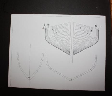


- 85 replies
-
- 2
-

-
- schooner
- effie m morrisey
- (and 1 more)
-
Thanks everyone. I will post progress over the next two days, then I'm outta here for a week in Loreto, Mexico with a bunch of friends for some male bonding (aka fishing, beer drinking, poker playing, and alas, a lot of naps now that we are getting a bit long in the tooth.) Allan
-
I have not personally built nor have I seen a fully framed model of a Grand Banks fishing schooner so I thought it would a fun project to try. There is a lot of information available on the Effie M. Morrissey, including a reasonable set of plans that are available from the Library of Congress, she is available to visit in her modern configuration, and there are folks in Massachusetts that have been more than willing to answer questions, so she seemed to me to be a good choice. The following is a compilation of her history from the internet, “so it must be true!” She was designed by George McClain and was the last fishing schooner built for the Wonson Fish Company. She was built with white oak and yellow pine and took four months to complete. She was launched February 1, 1894. Her hull was painted black and her first skipper was William Edward Morrissey, who named her after his daughter Effie Maude Morrissey. She fished out of Gloucester for eleven years then began fishing out of Nova Scotia. In 1914, ownership moved to Brigus, Newfoundland where Harold Bartlett used her as a fishing and coasting vessel along the Newfoundland and Labrador coasts. In 1925 Harold Bartlett sold her to his cousin, Captain Bob Bartlett, an Arctic explorer. Bob Bartlett had an auxiliary engine installed and reinforced the hull for use in the Arctic. In 1926 with financial help from publisher George Putnam , Bartlett began 20 years of exploration using the Effie. When Captain Bartlett passed away in 1946, Effie was sold to the Jackson brothers to carry mail and passengers in an inter-island trade in the South Pacific. On their voyage to the Pacific she developed problems at sea, forcing the crew to return to New York. On December 2, 1947, the boat caught fire while docked at the boat basin in Flushing, New York. The schooner was repaired and sold to Louisa Mendes in Massachusetts at which time she entered the packet trade in a trans-Atlantic crossing to Cape Verde. Upon reaching the islands, Captain Mendes re-registered the schooner under the name Ernestina, after his own daughter, and used her in inter-island trade. Ernestina made a number of transatlantic voyages and fell into disrepair at Cape Verde, where she remained until the late sixties when there was interest in the U.S. to save her. In 1977 the people of Cape Verde made a gift of Ernestina to the U. S. In August 1982 her hull was completely rebuilt and she sailed to the United States. In August 1988 the schooner made a return trip to Brigus, Newfoundland, on the 113th anniversary of Capt. Bob Bartlett’s birth. Ernestina was designated as a National Historic Landmark i with restoration being completed in 1994, and in 1996 became a part of the New Bedford Whaling National Historical Park. She is currently owned by the Commonwealth of Massachusetts. Effie is the oldest surviving Banks fishing schooner; the only surviving 19th century Gloucester-built fishing schooner; one of two remaining examples of the Fredonia-style schooners (the other being the Lettie G. Howard,) the only offshore example of that type; and one of two sailing Arctic exploration vessels left afloat in the United States. This is the fourth model going onto the building board in the attached photos. The model will be based on how she looked in 1894. In the photos you can see that the keel has a piece temporarily attached so it will sit at about a 2 degree angle to match the "drag" and make it easier to check that the frames are 90 degrees to the water lines (building board plane.) I am using Castello box for the keel and deadwood. The plans do not show a shelf along the bearding line of the fore or aft frames. Looking at photos of a rebuild of the schooner Virginia, there are no steps nor shelf. I have no idea if there was one on the original build. More to come, I hope. Allan


- 85 replies
-
- 7
-
-
- schooner
- effie m morrisey
- (and 1 more)
-
Your posts continue to be a delight Danny! I hope making the fine cabinetry on the tiniest parts was as much a joy as it is for us to see the photos. Allan
-
Richard, Your coppering job is extremely well done. Kudos Allan
-
My sincere condolences Suzanne, your father will be missed by all of us here. Allan
-
Brian and Sam The number and size of bolts varied for size of ship and whether it is the fore, main, or mizzen channel as would be expected. Samples follow: 64 gun 18 gun Main Channel Number of bolts 9 7 Bolt diameter 1.25" 7/8" Iron T-Plates or supports in lieu of wood 6 4 Fore Channel Number of bolts 8 6 Bolt diameter 1.25" 7/8" Iron T-Plates or supports in lieu of wood 5 3 Mizzen Channel Number of bolts 6 5 Bolt diameter 1.125" 7/8" Iron T-Plates or supports in lieu of wood 3 2 I found no mention of spacing for the bolts or the T-plates. Allan
-
Brian There are scantlings for sure on the size and number of bolts. I will take a look when I get home and have access to the Steel book. Allan
-
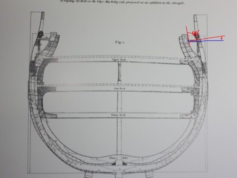
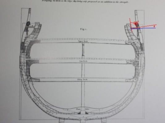
Did a little more digging as I was starting to doubt my own comments. The attached drawing is from David Steel. I have drawn in red lines that show the angle of the channel if it was 90 degrees to the hull. The red line is 8 degrees higher than horizontal. Also, what most models do not show is the gap between the hull and the channel. I do not know if it applies earlier than about 1800 but is written in Steel's Naval Architecture as follows: "They should fay to the sides only where the bolts come through, having an open space of about two inches in the rest of their length to admit a free current of air, and passage of wet and dirt, in order to prevent the sides from rotting." Allan
-
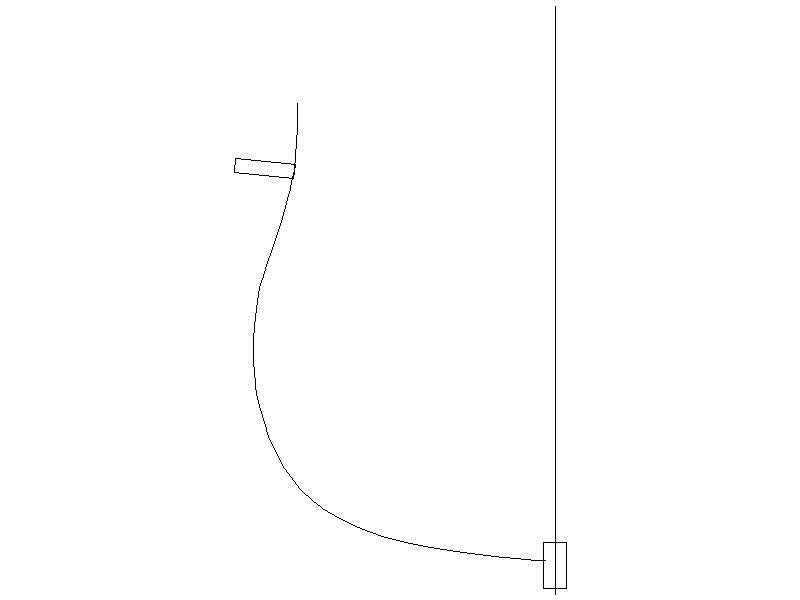
Hi Tom, Sorry to disagree, but the channels would not necessarily be parallel to the water if they are ninety degrees to the hull. It depends on where they meet with the hull. The attached shows what I mean. Now, I may be totally wrong on this but I have not seen the channels angled on contemporary models or drawings. Allan

-
You have a lot of good information so far, but here is a bit more to further confuse the issue. I believe the channels are not at ninety degrees to the hull, but rather they are horizontal. If there is a lot of tumble home or other curvature of the hull where the channels anchor to the hull and it is ninety degrees to the hull at that point, they may point up or down, not lay horizontal. Support brackets under the channel or knees were used on top. Iron Tee brackets were often used if under the channels while wooden knees were found mainly above. Allan
-
HMS Euryalus by egen -
allanyed replied to egen's topic in - Build logs for subjects built 1801 - 1850
Egen, The alignment of the carlings is terrific! Poor alignment can distract from the appearance quite easily. What changes did you make? I am curious to see if we made a mistake in the book and would like to correct if necessary. Thanks Allan -
I have not seen a frame with the groove on such small wood before. All I need is the right blade to give it a try on the next go around. Do you have any sequence photos of cutting the material and then the groove, (or vice versa?). Cutting such small material can be tricky, even if using box or other close grained woods. Allan
-
Ed, I have always struggled with the fixed blocks, including using small diameter end mills. The problem is that those with an appropriate diameter are too short to pass through the block so they have to be worked from both sides and of course they never quite match up.. I like your method and will definitely give it a go. Allan
-
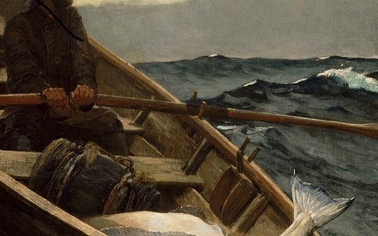
Ron, If you go with thole pins you will be in good company. The Fog Warning by Winslow Homer shows pins versus locks . Allan
-
Great lesson in that posting, especially the rule to NEVER run over the score a second time. Thanks for putting it up for us. Allan
-
I just went through 6 glass covers trying to cut them underwater. I tried with two different VERY sharp scissors, but no luck. If someone succeeds, please share your secret! Allan
-
I have put shavings of cedar inside some models to keep the critters out. I don't know how well this works, but at least they smell nice. Allan
-
TRULY amazing. Will the chess pieces be ebony and ivory? Allan
-
Hi Dan, The bulkheads that you have made are extremely nice work. The details are terrific and brought a point to mind that I had not thought about before. Did the battens run the full length and the doors a tad short so they cleared the battens, or were the battens cut at the point where the doors swung? I cannot find anything in contemporary text or drawings that gives a firm answer. I have only seen one paragraph in any publication, that being in Lavery's Arming and Fitting that says that the screen bulkheads had cants "to be fitted in three parts, thus leaving space for the two doors which adorned each bulkhead and they were to be removeable....." Thanks again for doing taking so much time in photographing your build. Allan
-
Thanks again Druxey. I was picturing counters, but thinking fashion pieces and the fact that they are so far above the water line, no need to hood the ends of the planks. Allan
-
That's a first for me Druxey. It makes complete sense though. What about on later ships where the lower planking wrapped around the fashion piece and ended at the tuck molding? Would the planking at the stern above the tuck molding have been hooded into the fashion piece? Thanks for this interesting new (for me) tidbit. Allan
-
I have and I use American Fishing Schooners: 1825-1935 By Howard Chapelle regularly. I love this book. If there is one negative for me for this book it is the fact that there is no index that makes sense. There is so much good information in the second half of the book, but none of the key items or words are in the index. Worse still, each item in the main text is presented alphabetically, and not necessarily categorically. Still, I believe this book would enable any builder of an American schooner to do a construct a very accurate and detailed model. Allan
-
Hornet, I am having a really hard time picturing this. The cotter pin has me baffled. Can you post a photo or two? Thanks Allan
-
HMS Euryalus by egen -
allanyed replied to egen's topic in - Build logs for subjects built 1801 - 1850
Use the lower deck beam, even if temporarily fit in place, to be the fit is correct. You can also use the upper deck beam temporarily to be sure the scores in the bitts are OK. The drawings are correct, but sometimes it takes a little bit field fitting to be sure the actual fit is correct. Allan