HOLIDAY DONATION DRIVE - SUPPORT MSW - DO YOUR PART TO KEEP THIS GREAT FORUM GOING! (Only 13 donations so far - C'mon guys!)
×


allanyed
-
Posts
8,149 -
Joined
-
Last visited
Content Type
Profiles
Forums
Gallery
Events
Everything posted by allanyed
-
 Thanks. I realize contemporary information may not even exist for this kind of information but trust that the work in your book was well studied and could be right on the money, Allan
 -
Using the well researched book by McKay is a brilliant move. Allan
-
Iron Braces on Hanging Knee Deck Supports... HMS Victory
allanyed replied to tmj's topic in Nautical/Naval History
Perfect, MANY thanks Gary Allan -
Thanks Phil, As mentioned in post #12, I asked about information based on contemporary sources. Does the book you mention provide a contemporary source for the drawing showing the pillar locations? Thanks again. Allan
-
Hi Richard, The overall breadth of the four strakes should be about 62". Looking at drawing ZAZ0121 at RMG Collections the main wale is indeed 62" from what I was able to scale up in low resolution and the ports do cut into the top strake of the main wale about 4 1/2" at midships. Looking at high resolution plans of other three deckers this is not unusual aft, but not as common midships. Drawing ZAZ0121 is the 1765 version so the 1803 version of Victory may not be exactly the same. https://www.rmg.co.uk/collections/objects/rmgc-object-79912 Allan
-
I have only seen them in deck drawings but very few show these. Sorry I do not remember where, but from what I recall they were all single stanchions on the center line except where there might be two in the area of a hatch. In that case they were in line with the coamings and often near the corner of the coamings and head ledges. I checked a half dozen contemporary contracts and they all give dimensions of the pilar ends but not location. For a first rate there may have been two under each beam rather than one on the center line. I am curious to see some contemporary information that some member might be able to share. NOTE: While the center section was often/usually square as mentioned above, keep in mind that this section usually had a heavy chamfer on all four corners. Allan
-
6-pounder, Royal Navy cannon barrel - George III era
allanyed replied to Gabek's topic in 3D-Printing and Laser-Cutting.
Scaling the photo that Ron posted the hole appears to be about 1/2" to 5/8" diameter. If anyone has something more definitive based on contemporary sources I would be grateful to know. Allan -
Iron Braces on Hanging Knee Deck Supports... HMS Victory
allanyed replied to tmj's topic in Nautical/Naval History
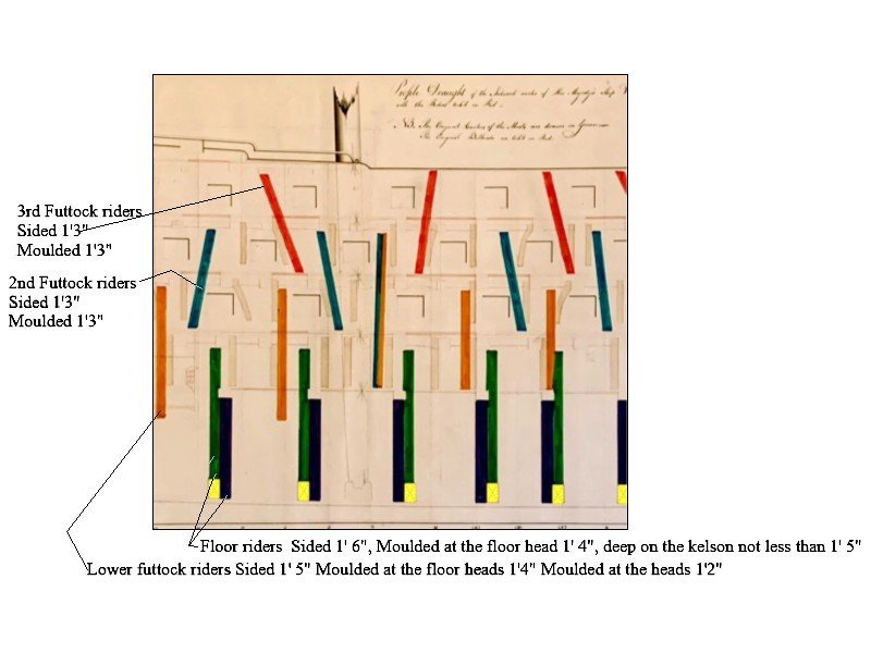
Hi Gary The best I can ascertain from the Steel scantlings is the first picture below and since I cannot find the dimensions of the upper most riders I am pretty sure I got this wrong. Can you correct this for me? I am wondering if the lower paired riders are both considered floor riders in which perhaps the second drawing would be correct. Or, is it possible the first drawing is correctly labeled and Steel does not include what might have been called top timber riders. Thank you very much.😀 Allan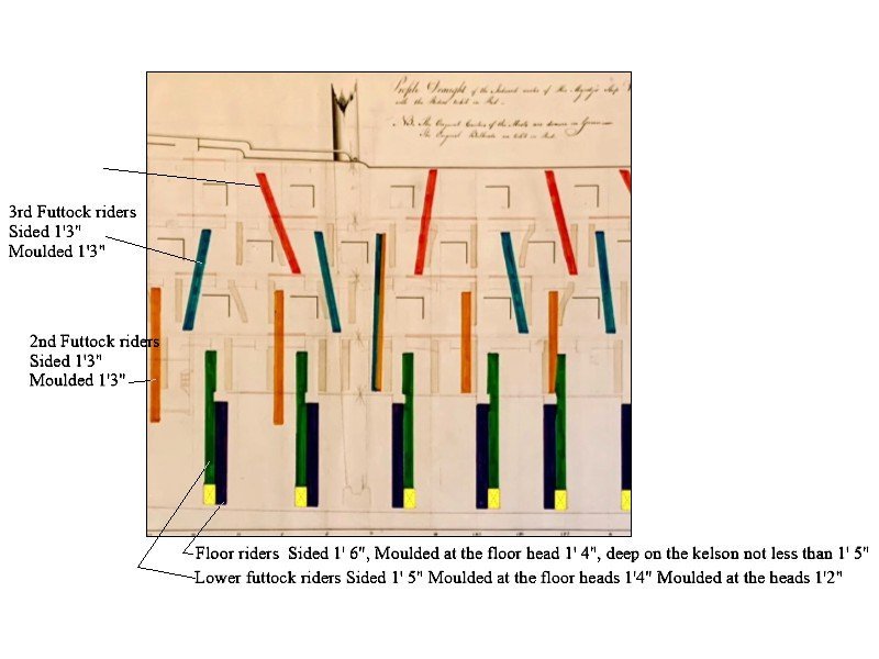
-
George It has been many years so I have no recollection of which skipjack. I do remember there was a great program at that time where they had inner city kids working in the yard and consequently learning trades while earning some money. Allan
-
Evan Is there a reason for not just removing the errant P6 plank and replace it with a plank that fits correctly? Allan
-
Hi Darius359au I realize it is probably another kit design error, but FWIW for the future or others building this kit, according to the scantlings from David Steel in The Elements and Practice of Naval Architecture 1805, the main wales of first rates circa 1805 were made up of four strakes, not five, and with a total breadth of 5' 2". They were 10" thick. The strake above and the strake below the main wales were 8" thick and subsequent strakes reduced for several strakes ending at 4 1/2" thick for the plank of the bottom. The strakes were likely top and butt or anchor stock rather than straight edge. The channel wales were made up of 4 strakes up to about 1790 but more likely 3 strakes after that time. Total breath was 3' 0" and the thickness 5 1/2" or 6". Allan
- 25 replies
-
- 2
-

-
- Victory
- Cross-Section
- (and 1 more)
-
Welcome to MSW Fred!!

-
Super warm welcome aboard George. I also love the skipjacks, and built a couple models based on information found at the St. Michaels boat yard and Steve Rogers' book The Skipjack. I was lucky when I last visited the yard as they were rebuilding a skipjack and gave me a piece of the original keel which I cut up and used for some of the parts on the last model. Hope to see more photos. What you show lucks great!!! Allan
-
6-pounder, Royal Navy cannon barrel - George III era
allanyed replied to Gabek's topic in 3D-Printing and Laser-Cutting.
Take a look at the drawing above that Ron posted, it should help you. We have been working on a similar project where-in we have 3D drawings of Browne (1625), Commonwealth (1650) Borgard (1716) Armstrong Frederick (1760) , and Blomefield (1791) patterns. Still have a ways to go with Armstrong (1725), additional Blomefields, Pitt, Spanish, and French patterns that are only complete in 2D at this time. The only noticeable difference between the Armstrong and Armstrong Frederick patterns is that there is no trough on the Armstrong pattern and the cypher is for George 2 rather than George 3. Otherwise, the breech, first and second reinforce, and chase along with the astragal rings are virtually the same based on drawings found in Adrian Caruana's The History of English Sea Ordnance volume 2. Allan -
Hello TJ According to contemporary information in David Steel's 1805 Elements and Practice of Naval Architecture, the pillars in the hold were not round at that period of time. Pillars under the orlop beams and gun deck - 13" square along the middle 3/4 of the overall length At the lower 1/8 of the length they are 16" fore and aft, and 14" athwartships At the upper 1/8 of the length they are 14" fore and aft and 13" athwartships. Under the middle gun deck beams, one per beam, 8 inches square at the top and 9 inches square at the bottom. Under the upper deck 6 inches square at the top and 7 inches square at the bottom except for 2 1/4" square iron pillars at the capstans and galley. As normal, anything found on Victory today should be checked against contemporary information for the time period the model represents. Many of the details today are different than what she actually looked like at various times of her existence. In the end, your choice. Personally I think the rounded pillars have more character but they may not be realistic if accuracy is a criterion. . Allan
-
There are way to make these yourself that will yield nice results. If you do not have an electric drill or lathe, you can make them with separate pieces, square stock and dowel. Drill holes in the square ends to the diameter of the cylindrical piece and assemble. You can also glue flats at the ends onto dowels of the proper diameter then sanding and filling with saw dust will yield nice results as well. Finding these already made to the dimensions you want is unlikely. Perhaps some member here with a lathe will make them for you if you provide a detailed dimensioned drawing. Allan
-
6-pounder, Royal Navy cannon barrel - George III era
allanyed replied to Gabek's topic in 3D-Printing and Laser-Cutting.
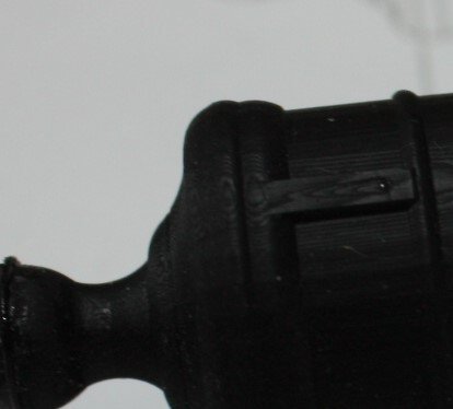
Hi Gabe Thank you for sharing this. Will you be adding the trough around the vent? Do you or does any member know the vent diameter? Allan -
Size of a printer needed
allanyed replied to Frank Burroughs's topic in Modeling tools and Workshop Equipment
No matter the printer, draw a test piece with a rectangle that is 5"X 6" or some such dimensions that can be measured with a caliper or other accurate device. Then print it and measure to see if it is accurate. Not all printers are created equal. I always take a caliper to a print shop when I need larger prints. Retail print shops like the old Kinkos rarely got it right the first time but were able to make adjustments. Architectural firms are a better way to go if you cannot get accurate prints at home. Allan -
Welcome to MSW Willy!! The model in the photo does not look like any contemporary or modern drawings of Peacock that I could find. Maybe Peacock was an exception, but It appears to have too many yards/sails rigged to each mast than would be found on a sloop of war. Allan
-
Ciao Giuseppe. Welcome to MSW!!! Allan
-
You could have a lot of company as that is maybe why the master model builders of the 17th and 18th centuries did not always include ordnance of any kind and when they did, rigging the cannon was often left off. 😀 Your photo shows double and single blocks so I was curious if these are all for the cannon? Adrian Caruana points out in his book, The History of English Sea Ordnance Volume II page 386, only 32 pounders and larger had a single and double block set up for both the train and running out tackle. All other calibers had only single blocks. I would not be surprised if there were exceptions, as is often the case for us, for other large calibers such as the 24s to have a single and double. Allan
- 562 replies
-
- 5
-
-
- vanguard models
- alert
- (and 2 more)
-
Older topic and from what I could find, a new question.... apologies if this had been asked and answered elsewhere. When did merchantmen and naval vessels (Spain in particular, European in general) start tarring standing rigging as a common practice? Thanks Allan
-
Iron Braces on Hanging Knee Deck Supports... HMS Victory
allanyed replied to tmj's topic in Nautical/Naval History
Hi Morgan Could you post this as a new subject in the Ship's Plans and Project research forum as I believe a lot of member would like to follow this and may not see it here in TMJs "iron braces" topic. Thanks Allan -
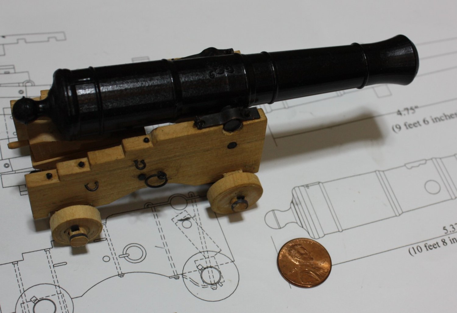
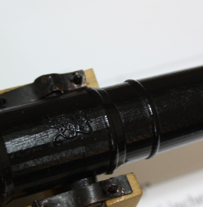
Thanks to fellow member Ron Thibault's work in preparing 3D drawings of the Armstrong Frederick pattern, a realistic barrel was easy to have made. Details of the George III cypher and the flash pan as well as astragal rings can be seen below. Allan

-
Warm welcome to the fray Michael. A motley group we may be, but a more helpful crew you will never see. Allan