allanyed
-
Posts
8,149 -
Joined
-
Last visited
Content Type
Profiles
Forums
Gallery
Events
Everything posted by allanyed
-
 Nice looking boat! Maybe something you would like for your files ,boat scantlings PDF is attached below. These are circa 1800 and there were small variations over time so the dimensions are not cast in stone. From W.E. May Allan Boat Scantlings 1-28-14.pdf
- 443 replies
-
- 2
-

-
- Indefatigable
- Vanguard Models
- (and 1 more)
-
Calculating rope thickness (Fictional ship)
allanyed replied to Harry12's topic in Masting, rigging and sails
Harry. I calculated the diameter at 1.81 inches then scaled it to 1:48 1.81/48=0.0377. IF your scale is something else, just divide the 1.81 by the scale you are using then convert to metric if you prefer metric. Allan -
Calculating rope thickness (Fictional ship)
allanyed replied to Harry12's topic in Masting, rigging and sails
The model you show is really well done and if you want black rope go for it. You can always just get tan rope and stain it with India ink or wood stain. India ink is acidic so wood stains may be better. Hopefully other members will have suggestions of stains that are appropriate. Keep in mind that the ship is fictional and the model they made is not accurate in some respects. For example it shows belaying pins which were not prevalent until much later in the 18th century. In the end, do what makes you happiest, this is a hobby after all. Allan -
Calculating rope thickness (Fictional ship)
allanyed replied to Harry12's topic in Masting, rigging and sails
Dark brown is realistic. IF tarred rope was used it would have been pine resin or something similar and the color would be dark brown, never black. Kits often include black which is not correct in the majority, or perhaps all, cases. 17th century models often had untarred rope on the standing rigging so the era is something to consider. If you are staying with the 18th century rigging, dark brown is the way to go, not black. Allan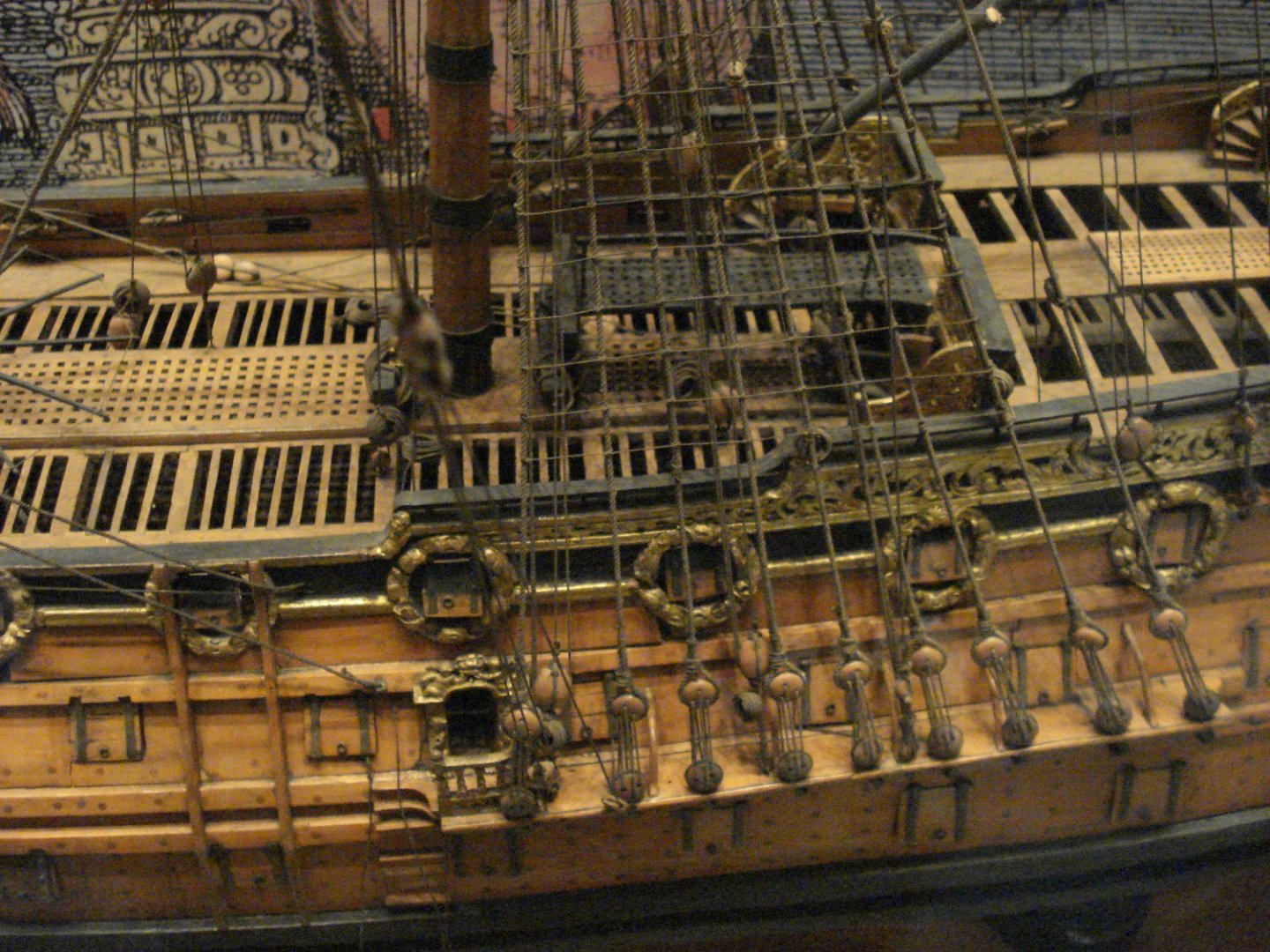
-
Calculating rope thickness (Fictional ship)
allanyed replied to Harry12's topic in Masting, rigging and sails
I am pretty sure you have nothing more to do other than start the program by hitting the enter data button at the top, but you put the two dimensions in the first rate box. Your ship is closer to a fifth or sixth rate. I have no idea if the results would actually change. Long hand using the ratios in Lees (88+26)/2=57 57/3= 19 so the mast diameter is 19 inches The circumference of the main stay is 0.5X 19=9.5" The circumference of the shroud is 9.5X 0.6 =5.7" The diameter/thickness is 5.7/3.14159= 1.81" At a scale of 1:48 it is 0.0377" or 0.96mm so 1mm should do well for you if you are building to 1:48 scale. The diameter for the foremast will be smaller and for the mizzen smaller still. For the foremast most people would not notice if you use the same diameter as for the foremast. For buying rope, where are you located? -
Do the kit ladders all have only three steps? The distance between the orlop deck planks to the top of the lower gun deck planking is about 80". Thanks Allan
-
Transom drawing question
allanyed replied to Pirate adam's topic in CAD and 3D Modelling/Drafting Plans with Software
Thank you very much Adam Allan -
Calculating rope thickness (Fictional ship)
allanyed replied to Harry12's topic in Masting, rigging and sails
The shroud circumference is 0.6 X the stay of that mast. The lower stay was half the diameter of the appropriate lower mast. Depending on the era, the mast diameter was 0.9 to 1 inch for each 3 feet of length. The length of the main mast was 2.4 the beam up to 1669. From 1670 you add the length of the keel, breadth of the ship and depth of the ship, then divide by 1.66. Then, if the beam exceeds 27 feet deduct from the total the amount that the beam is in excess of 27 feet, If the beam is less than 27 feet add to the total, the amount that the beam is short of 27 feet. From 1711 it is the length of the lower gun deck plus the extreme beam (outside of the planking) and divide the total by two. This is all from Lees' Masting and Rigging Allan -
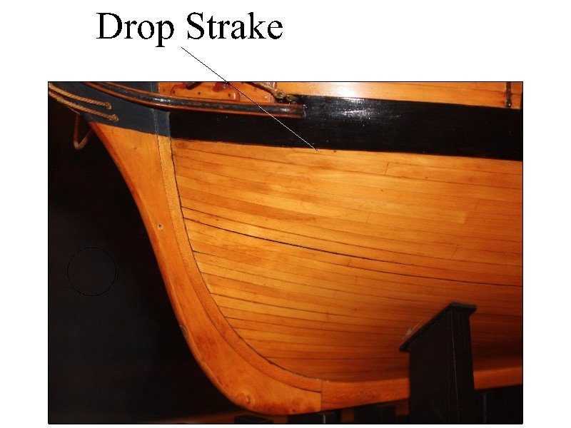
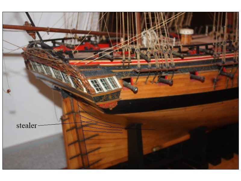
If you wind up doing a hull without copper or just leave it plain wood for any reason, there usually are no stealers at the bow, but there were sometimes drop strakes. There were times when stealers were used aft which were to fill an open space where as the drop strakes forward were used because of too little space. Hope this makes sense.
- 261 replies
-
- 7
-
-

-
- Victory Models
- Pegasus
- (and 3 more)
-
Transom drawing question
allanyed replied to Pirate adam's topic in CAD and 3D Modelling/Drafting Plans with Software
I just double checked and now I am confused. I missed that Steel indicates that there is a filling transom between the wing and deck transom AND two filling transoms below the deck transom for a total of five. Part of my own confusion is that he gives the space between the wing and filling transom below it as 2.5" but there is no space given between that filling transom and deck transom. The Shipbuilder's Repository 1788 has a filling transom between the wing transom and deck transom but no indication of transoms below the deck transom. The Establishments give scantlings for the filling transoms and space between them but no information as to how many filling transoms there are. And to add more confusion, the following is from a 28 gun ship the Aurora, 1776. She is slightly larger than Porcupine and Crocodile Porcupine Length 114 ft 3 in (34.82 m) (overall) 94 ft 2 in (28.70 m) (keel) Beam 32 ft 2+1⁄2 in (9.817 m) Aurora Length 120 ft 6 in (36.73 m) (overall) 99 ft 4 in (30.28 m) (keel) Beam 33 ft 7 in (10.2 m) From the Aurora contract: WING TRANSOM … The Wing transom to be sided 11½ ins, & moulded at the ends 13 ins, in the Middle 20 ins No Chocks to be admitted on the Aftside, & to be bolted to the Post with 2 bolts of 1¼ inch diameter & to be left 13 ins in the middle for the better room for the bolts. FILLING TRsm To have two Transoms between the Wing & deck Transoms sided 10 ½ ins & to be left for air between the wing & filling & each other 4 ½ ins & filling & deck planks 5” & to be to be bolted to the post with one bolt of one in diameter. The Chocks on the Aft side, if any not to exceed 12 ins, DECK TRsm The Deck Transom to be sided 11 ins & moulded a broad as may be for the better fastening of the plank of the Deck, bolted to the post with one bolt of one in diameter. ~~~~~~~~~~~~~~~~~~~ OTHER TRsm To have one whole Transom below the deck Transom free from shakes to be sided 10 ins to lye 3” clear of the deck Transom & both this & the deck Transom kindly grown as not to require the Chocks of the Breech to be too large. ~~~~~~~~~~~~~~~~~~~~~~ Which ship is your drawing? Allan -
Calculating rope thickness (Fictional ship)
allanyed replied to Harry12's topic in Masting, rigging and sails
Welcome to MSW Harry!! Hope you post some pics as this sounds like a very interesting project. Regarding the rigging, it is almost always given in circumference rather than thickness (diameter) so you will have to do some converting. There is a chart here at MSW where all you have to do is enter some basic data and it will give you the dimensions of the masts, yards, and rigging lines. The Disney series was taking place about 1728 but the ship design looks more like 17th century. The earliest you can use with the chart is 1627 and 1640 or you can use 1711. DO NOT USE 1670 as the spread sheet is completely wrong for 1670-1710. Go to https://thenrg.org/resource/articles and scroll down to the rigging spread sheet by Danny Vadas. In actual practice for your build, depending on your scale, you can probably just use 7 or 8 different size lines and it will look good so you can just use the chart as a general guide. Good luck Allan -
https://www.modelshipbuilder.com/page.php?224 Scroll down to the Hancock Allan
-
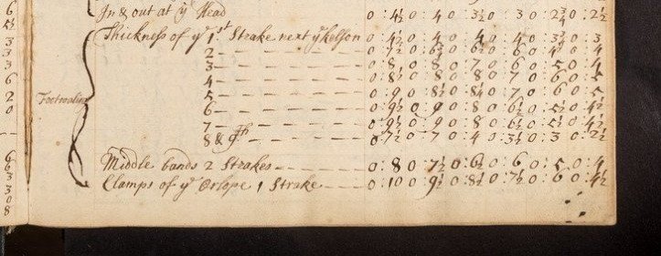
Purely a guess but unless things changed drastically between the 16th and 17th century there would have been inboard planking. The below is from a 17th century set of scantlings where you can see dimensions of various planking inboard for the 6 rates of ship.
-
Transom drawing question
allanyed replied to Pirate adam's topic in CAD and 3D Modelling/Drafting Plans with Software
In the scantlings in The Elements and Practice of Naval Architecture by Steel, Folio IV, it gives a total of four transoms with dimensions for a 24 gun ship. These include the wing, deck and two filling transoms for a 24 gun ship so match up with the contemporary plans of Porcupine, Crocodile, Squirrel, Pelican, Syren, and others. Where did you find Steel showing five transoms for a 24? In the Steel scantlings that I have, the smallest ship with five transoms is a 38. I would go with Steel scantlings and the contemporary plans rather than a modern publication. I looked at 28's and the ones I studied all had two transoms between the wing and deck and one filling transom below the deck transom. Larger ships, but not enough for an extra transom??? Allan -
Tightening shrouds and ratlines
allanyed replied to Charlie pal's topic in Masting, rigging and sails
Thanks Phil! I may be working on a new project shortly, but even so, rigging will be months down the road so whenever you get to it, I look forward to hearing the results. Enjoy your vacation!! Allan -
Chisel hone guide question
allanyed replied to CPDDET's topic in Modeling tools and Workshop Equipment
Clever!!!! -
She is a beautiful model! Your planking was done so well that I am sad to see paint covering your great work. Allan
-
Even the old masters often rigged models without sails but they all still included the running rigging. Your choice in the end, but you already have running rigging in place why not do the rest. There is no good way to install the booms without the lifts and such, which is running rigging, and already installed. Is there a reason you ran tarred lines through some of the blocks (your last photo of the boom tackle)? I would guess that they would gum up the sheaves in no time. It may just be the photo but those lines look black, thus my question. Very nice looking model Boerscht! Allan
-
Tightening shrouds and ratlines
allanyed replied to Charlie pal's topic in Masting, rigging and sails
Very interesting idea Phil. I hope it works and please do post photos for us. TIA Allan -
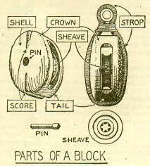
Picture and a thousand words and all that.....😀 I realize most do not include an actual sheave, but I show it as if were there. The first picture shows how the line ran and how you ran yours. The first two pictures show old style rope stropped blocks akin to those most commonly used up to the middle/late of the 19th century and the third photo shows internally stropped blocks. I THINK the internally stropped blocks would more likely have been used on the J Class Endeavour unless they had already gone over the blocks with metal shells. Hopefully some member will have that information if it is of importance to you. Those in the last photo are from the Syren Ship Model Company.


-
The build looks great. Two suggestions, hope you don't mind. I have used automobile pin striping for the white stripe with success. It takes covering with clear finishes without degrading or lifting, and lasts at least 13 years at last count on one that I built back in 2010. It has been literally at sea since October 28, 2010 so unaffected by ocean conditions. I really am not trying to nitpick but thought you might want to know that your blocks are upside down. 🙃 Allan
-
Hi Gregory In the pages where Caruana writes about the running out tackles and train tackle he makes reference to Falconer's Universal Dictionary of the Marine, 1769 and the Regulation of 1765 (found in the Public Records Office WO 55-1745). I have no idea where he specifically found this detail of the use of a single and a double block or if he based it on his own conjecture using what information he did find. About the only other way to tell would be to see the regulated inventory of blocks which he also mentions. Regarding the inventory unfortunately he does not write about the type of blocks, only the total quantities. Allan
- 562 replies
-
- 1
-
-
- vanguard models
- alert
- (and 2 more)
-
Even though they are from the 18th century there are great photos of a longboat that may be of some help on the RMG site https://www.rmg.co.uk/collections/objects/rmgc-object-66291 There are also sail plans for various boats of 1869 at RMG https://www.rmg.co.uk/collections/objects/rmgc-object-87011 and https://www.rmg.co.uk/collections/objects/search/de horsey rig W.E. May gives sizes of running and standing rigging lines as well as mast and boom diameters for various size boats. on pages 98 to 104 in his book The Boats of Men of War Allan
-
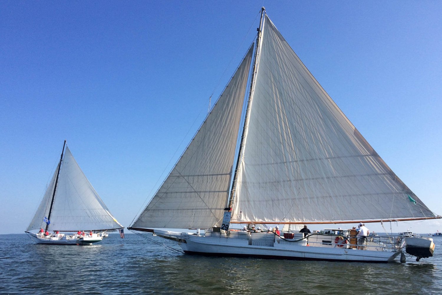
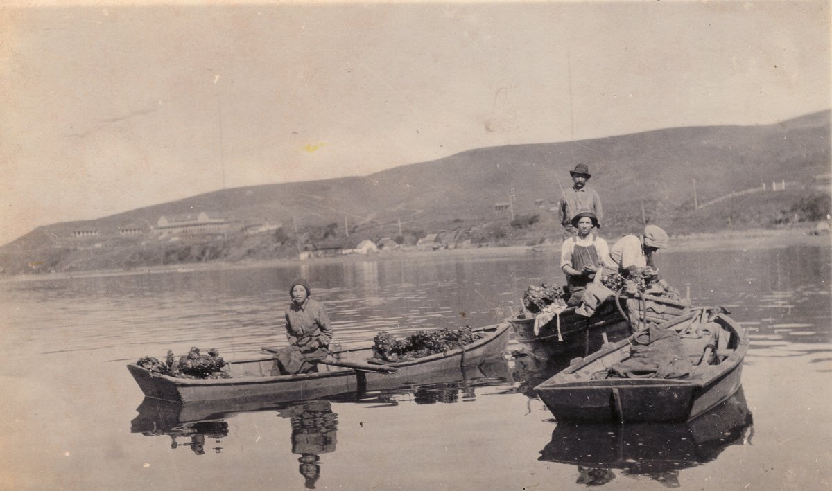
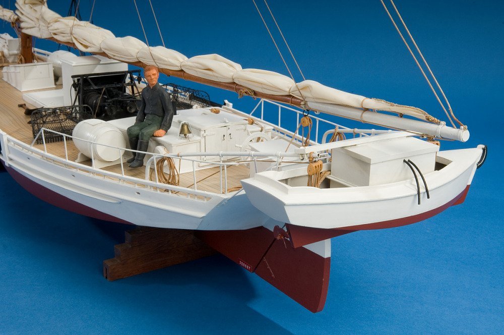
One of the old time oyster vessels is the skipjack used in the Chesapeake, and their small boats that hung from davits on the stern. There are several builds here at MSW on these vessels you may find interesting. The first pic below shows a pair of Morales Bay Company boats, quite different than the Chesapeake skipjacks. Your model could very well suit, but maybe consider removing some of the thwarts which were meant for multiple rowers. Allan

-
I have no ideas where the gear was stored when not in use, but found the following very interesting. From Brian Lavery: Holystoning was a routine activity on Royal Navy vessels until the early 1800s. The practice reached its height in 1796 when Admiral St Vincent recommended to his captains that the decks of all ships in the fleet be holystoned "every evening as well as morning during the summer months." For a ship of the line, the practice could take up to four hours. St Vincent's successor, Admiral Keith, rescinded the order in 1801, finding that "the custom of washing the decks of ships of war in all climates in every temperature of the air, and on stated days let the weather be what it may" was so onerous as to be damaging the health and lives of the crews. The practice was subsequently limited to once every seven to fourteen days, interspersed with sweeping. The after hold was the common area for ready to use things other than food and spirits so MAYBE that would be appropriate. I too would be very interested in finding out where these things would be stored based on contemporary sources. Allan