
HOLIDAY DONATION DRIVE - SUPPORT MSW - DO YOUR PART TO KEEP THIS GREAT FORUM GOING! (Only 13 donations so far - C'mon guys!)
×


allanyed
-
Posts
8,149 -
Joined
-
Last visited
Content Type
Profiles
Forums
Gallery
Events
Everything posted by allanyed
-
 Hi FM At the scale you are working, very nice work. Just curious as your topic is titled fishing boat, but with seven thwarts, it strongly resembles a ship's boat circa 17th-18th centuries. No matter, very neatly done! Thanks for sharing! Allan
 -
18-Pounder Pivot Gun
allanyed replied to AndyHall's topic in CAD and 3D Modelling/Drafting Plans with Software
https://www.rmg.co.uk/collections/objects/rmgc-object-85013 for a contemporary drawing from the Dolphin 1836 and Rapid 1840 Allan -
FM They do not have logs as far as I know, but rather really fine books. Examples of where to buy them are below, but you can find more with a quick search. Ships in Miniature by Lloyd McCaffery, Ship Models in Miniature by Donald McNarry, Building a Miniature Navy Board Model by Philip Reed . Used copies can be found on the net. https://www.amazon.com/SHIPS-MINIATURE-Classic-Manual-Modelmakers/dp/0851774857 https://www.thriftbooks.com/w/ship-models-in-miniature_donald-mcnarry/809946/item/11675885/?utm_source=google&utm_medium=cpc&utm_campaign=pmax_high_vol_frontlist_under_%2410&utm_adgroup=&utm_term=&utm_content=&gclid=CjwKCAjwgsqoBhBNEiwAwe5w05wB-HnnCRai6e9CtxTveUJykqoZNyCqe5-ln8wsDXSZI03IEQOltxoC0xIQAvD_BwE#idiq=11675885&edition=3619299 https://www.abebooks.com/9781848320178/Building-Miniature-Navy-Board-Ship-1848320175/plp
-
Ferrus manus.... (that looks like a flesh hand in the photo😀) Have you looked at the methods used in the books by the masters of the tiny scale, McCaffery, McNarry and Reed? They cover how to make rigging items such as blocks, what materials to use for lines, and more. Your scale is larger by comparison, but there may be some great tips for you. Allan
-
To me, the most remarkable thing is that those craftsmen 250 years ago had no electrical tools at all. The patience and skill they had to create these works of art is incredible. Allan
-
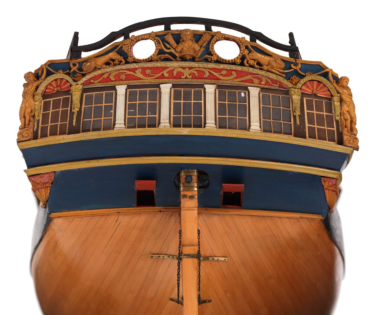
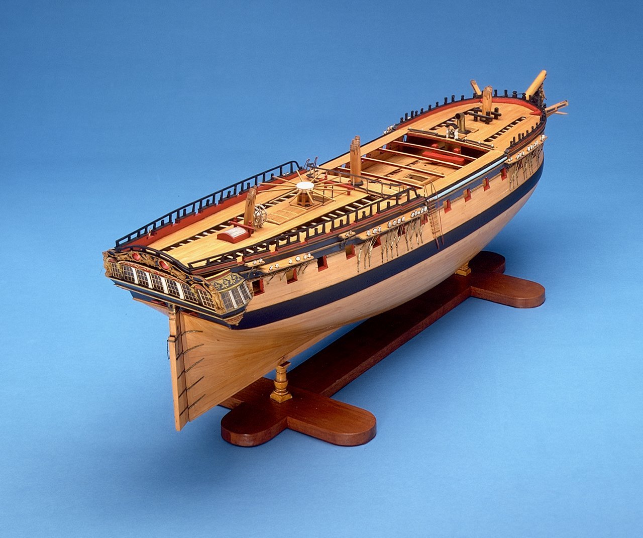
NB Using filler blocks is a wise move. If you have not already studied it, the contemporary model at RMG may be of some help not to mention the plans they have of Diana 1794. Note that as she is post 1790, she does not carry her name on the stern which was by Admiralty orders (maybe not universally adhered to😀) https://www.rmg.co.uk/collections/objects/rmgc-object-66303
-
Size bears no relation to quality
allanyed replied to Toolmaker's topic in Modeling tools and Workshop Equipment
THANK YOU PAUL!! -
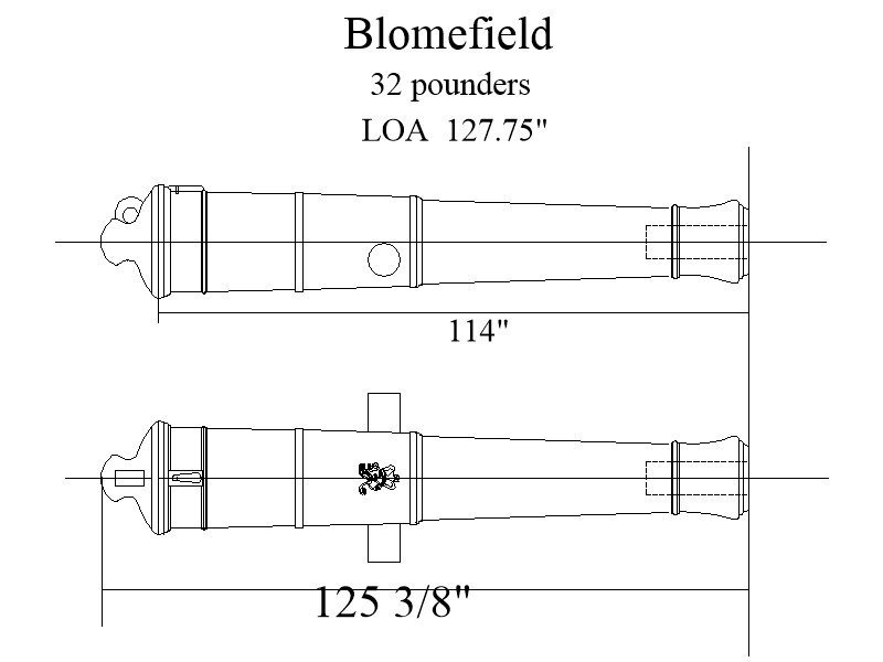
Darius359au I believe the designated gun lengths are from the muzzle to the breech, (basically the length of the bore,) not the length of the cannon barrel. For the 9' 6" barrel, the overall length would be about 10' 5 3/8" as shown below. I don't know where you are located but here in the USA I paid about $15 for 20 Commonwealth pattern cannon printed in black resin, including shipping that were fantastic. For the Blomefield pattern, we only have the 3D drawings for the 9 and 18 pounders so far. Allan
- 25 replies
-
- 1
-

-
- Victory
- Cross-Section
- (and 1 more)
-
Size bears no relation to quality
allanyed replied to Toolmaker's topic in Modeling tools and Workshop Equipment
Definitely not the one I have. I will do a bit of research to see what I can find similar to your yours. Thanks Paul Allan -
Size bears no relation to quality
allanyed replied to Toolmaker's topic in Modeling tools and Workshop Equipment
I love the tool holder. I have one but it is a Veritas and a great device but it has not worked for me on my very narrow carving chisels. Is the holder/guide you use commercially available? Thanks!! Allan -
Montanes by Iseaz - OcCre- 1/70
allanyed replied to Iseaz's topic in - Kit build logs for subjects built from 1751 - 1800
It looks like it may be too late on this project but did you look at printed cannon? I have purchased them at 1:64 for about $0.75 a piece including shipping (in the USA). I sent an STL drawing of each size to the printer and had them back in about a week. They are as detailed as the drawings including the cypher even at that small scale. I have 2D drawings of various size Spanish barrels used circa 1765-1808 and 1718-1765 but we have not gotten to these in 3D yet. You are welcome to the 2D if you want to get them done in 3D drawings so you can get them printed. A larger scale printed British barrel of 1760 can be seen https://modelshipworld.com/topic/35120-armstrong-frederick-cannon-by-allanyed-124-scale/ to get an idea of the detail. Smaller scale pieces are below in the British Commonwealth pattern circa 1650-1716 Note the conical trunnions for that period. Allan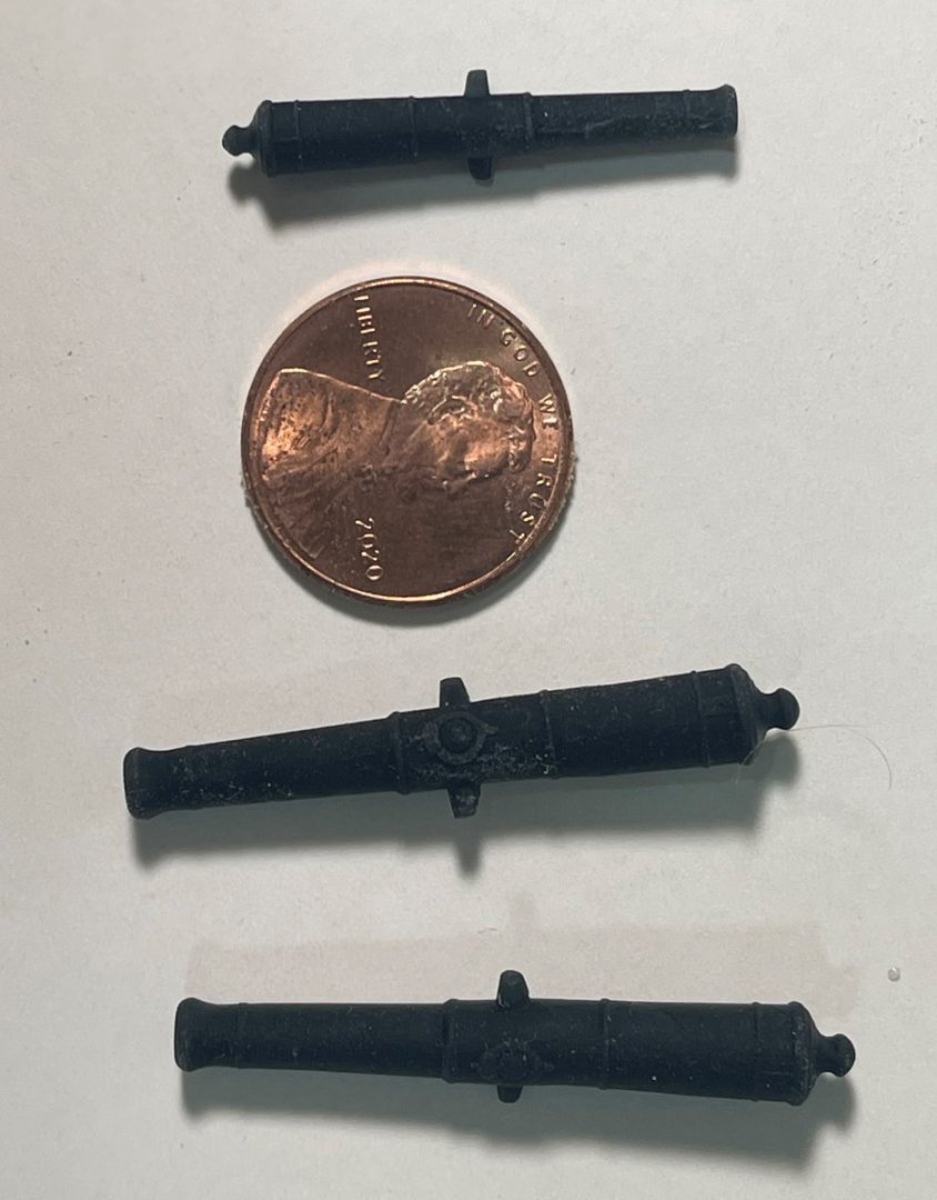
-
taper the top timbers/ribs of the plattforms!??
allanyed replied to Theodosius's topic in Masting, rigging and sails
You mention the ship Mars but then the Speedy. There were many ships named Mars from different nations so a clear answer is not easy. Assuming you are speaking about the Speedy of 1782. If you use the design by Steel shown in James Lees' The Masting and Rigging of English Ships of War dated 1795 it may be OK. He also shows a version from a model built to the 1745 Establishment that is similar. Earlier and later designs were different. The photo below is from The Masting and Rigging of English Ships of War page 23 ISBN 0-87021-948-0 The battens taper from 4 inches thick to 2 inches thick according to Lees. The outer part of the battens rest on top of the rim rather than ending at the same height. Maybe too complex to duplicate at 1:64, but adding the taper to the battens should be reasonably easy. Allan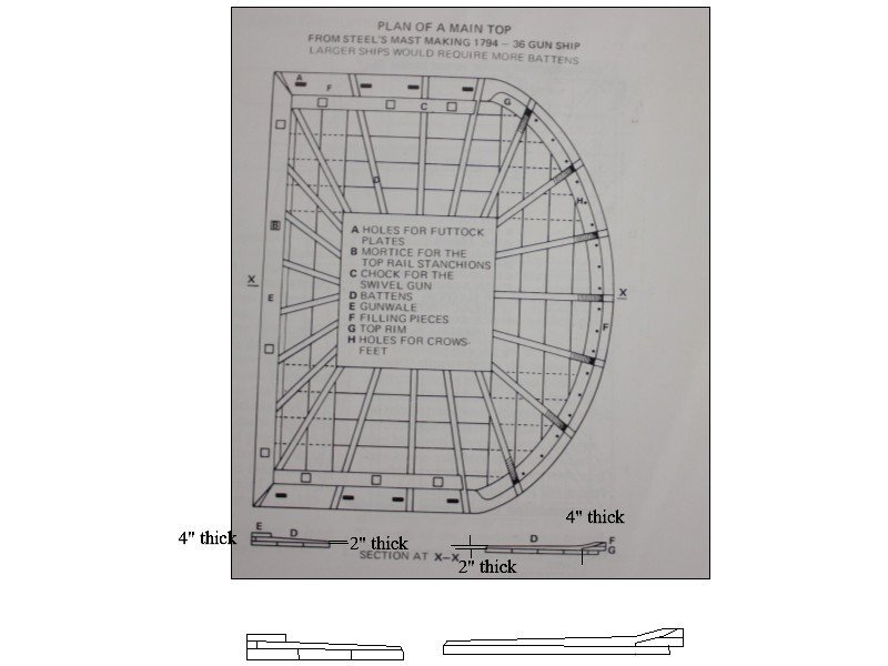
-
Kolvir Don't neglect the contemporary drawings at RMG Collections - https://www.rmg.co.uk/collections/objects/search/Valiant plans - and the scantlings which can be found in the book Scantlings of Royal Navy Ships which includes the 1719, 1745, and 1750 Establishments. They should make for a complete set of information for you. The plans on the RMG site are low res but you can buy high res from them although they are not cheap. There are five high res plans of the 74s Ramillies' (1763); 'Terrible' (1762); 'Russell' (1764); 'Invincible' (1765); 'Magnificent' (1766); 'Prince of Wales' (1765); 'Marlborough' (1767); and 'Robust' (1764) on the Wiki Commons site that you may find to be better as they are super clear and will be apropos for a mid 18th century 74. They can be found on page two of https://commons.wikimedia.org/w/index.php?title=Category:Ship_plans_of_the_Royal_Museums_Greenwich&filefrom='Hayling'+(1760)+RMG+J0259.png#mw-category-media Hope this is a little help. Allan
-
Hi Mr. Kolvir Did you watch the You Tube video by Olga Batcharov that shows a LOT of pages of this book? If I was building a 74 built to the 1750 Establishment I would invest the $30 needed to get it. This should go well with the five contemporary plans of Valiant at the RMG Collections site and the scantlings from the 1750 Establishment which are readily available as well. This could be a really good project! Allan
-
Your build is fun to watch, your work is lovely! Gonna be fun not breaking the sprit or knocking over the model while maneuvering with the rigging. Hope you do not get bitten 😀
- 443 replies
-
- 3
-

-
-
- Indefatigable
- Vanguard Models
- (and 1 more)
-
Hi Bob, It is super that you went ahead with building your own ship's boat. (There were no life boats back then 😀) For the future and for those that may be building this kit there is a good set of scantlings for ships' boats available that can be found in Boats of Men of War and Scantlings of the Royal Navy. Attached is the Excel version. Note the breadth of the thwarts for example. They would have been about 9.5" (0.15" at 1:64) broad. Looking at contemporary plans there is about a 21" (0.328" at 1:64) space between them. (There were variations over the years and regarding the type of boat, but 8 to 10 inches would be about right.) For a 14 gun sloop there were likely a 16 foot long boat or launch and a 24 or 25 foot pinnace. In 1777 an 18 foot cutter may have been added. These were probably all single banked, not double banked as the kit shows. There are a number of high resolution plans for various types of ship's boats on the WikiCommons site as well as a lot in low res on the RMG Collections site that may be of help as well. Allan Boat Scantlings 1-28-14.xlsx
- 254 replies
-
- 5
-

-
-
- Victory Models
- Pegasus
- (and 3 more)
-
THANK YOU!!! Allan
-
Hi Gregory, Remember that post #9 refers to pillars in the hold, not on other decks. I am not convinced the pillars in the hold were ever turned. As to the other decks, based on the contracts and plans turned pillars seem to be the norm. In looking at several contemporary contracts the wording has me convinced the pillars in the hold were probably always square and those on higher decks turned. When they are to be turned it is so specified in the following contract samples. Astrea (36) and Curacoa (36) 1808 The Pillars in Hold under the Lower Deck and Orlop beams to be square 7½ inches at the Lower End, and 7 inches at the Upper End. The Pillars under the Upper Deck Beams to be 6½ inches square at the Lower End, and 6 inches at the Upper End, and turned. Elephant (74) launched 1786 The Pillars in Hold under the Gun Deck and Orlop Beams to be 9¾ inches square at the lower end, and 8¾ inches at the upper end. The Pillars under the Upper Deck Beams to be 8½ inches square at the lower end, and 7½ inches at the Upper End, and turned. To have Pillars to the Quarter Deck Beams, handsomely turned 6 inches square at the lower end & 5 ¼ inches at the upper, Severn (50) and Burlington (50) 1695 To place under Each Beame in Hold and Upon the Kelson one Pillar. To be Seven Inches Square. Upper Gun deck To place Two Tire of Turned Pillars in such Places as are Convenient Under ye Beames fore and aft, Six Inches square. Lark (40) 1702 To place under Each Beame in Hold and Upon the Keelson one Pillar. To be Six Inches Square. Upper Deck to place Two Tire of Turned Pillars fore and aft in such Places as are Convenient Under ye Beames, to be Five Inches square.
-
Craig, what is the ZAZ number on the bottom left, I cannot make it out? THANK YOU Allan
-
Hi Gregory, Turned pillars may very well have been a common sight in 1757 regardless of the Admiralty Establishments. But, this is a topic circa1805 so turned pillars may not be apropos. No matter, there always seem to be exceptions regardless of whatever the norm might have been at any given time and regardless of what the Admiralty called for. Ain't that the truth! 😀 Allan
-
Planking Bow
allanyed replied to Loracs's topic in Building, Framing, Planking and plating a ships hull and deck
Hello Mr. Lorac Study the planking expansion drawings in the RMG Collections site. You can download into a drawing program then measure each strake to get an idea if they are consistent in tapering. Go to the collections site (https://www.rmg.co.uk/collections) and type in "planking expansion plans". Be careful that you are looking at outboard, not inboard expansions as some drawings show one or the other and others show both on the same plan. Woolwich 1785 and Squirrel 1785 are good examples. Allan -
Hi Rick Goodwin describes these as being the main bilge pump on fourth rates and below. On larger rates they were used for taking water from holes in the hull or from cisterns. The Construction and Fitting of English Ships of War, page 142. I have no idea how they were employed on American ships. Allan
-
Whatever water was in the bilge which could be fresh from rain water mixed in with the normal sea water that was found in the bilges. Certainly not fresh drinking water. Allan
-
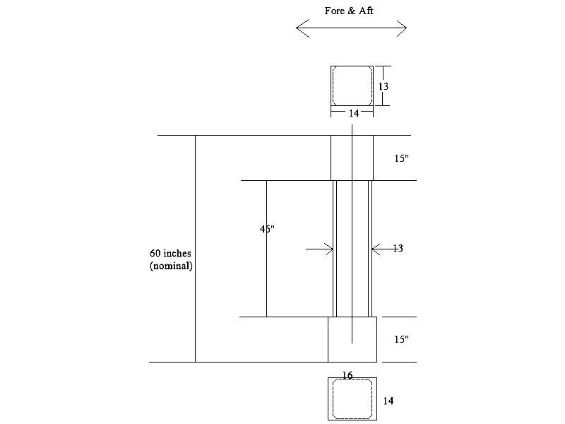
Gregory, You may right that McKay is right and Steel got it wrong. I was just going by Folio XVI of Elements and Practice of Naval Architecture as Steel was a couple years after the period in question and he was basing information on actual practice at that time. I am sure there were other designs, I was only pointing out what Steel wrote as it was as close to the 1803 date in question as I could find. For example in the The Shipbuilder's Repository of 1788 on page 290 it gives dimensions of the square ends only, it does not make mention of a shape for the area between the ends. Maybe in that book it assumed it could be square with some chamfering or octagonal or round. If you go back to the Establishments of 1719, 1745, and 1750 , they are specific that the pillars are all square from top to bottom. Maybe the sketch below will help regarding Steel's specific comments that the middle section is to be square. The lengths are of course going to vary by deck and location but the cross section dimensions are those given by Steel for a first rate. I added the chamfer as well. Allan
-
Hi Gregory, I only have what Steel wrote in the scantlings pages. It is written that the pillars were square, but I imagine the four corners in the middle 3/4's square section were chamfered. I would be very interested to see other contemporary information with additional descriptions. I would not be surprised if there were other shapes and dimensions coming out of the various yards. Seems there is very little fixed in stone in those days. Allan
