HOLIDAY DONATION DRIVE - SUPPORT MSW - DO YOUR PART TO KEEP THIS GREAT FORUM GOING! (Only 68 donations so far out of 49,000 members - Can we at least get 100? C'mon guys!)
×


allanyed
-
Posts
8,149 -
Joined
-
Last visited
Content Type
Profiles
Forums
Gallery
Events
Everything posted by allanyed
-

Navy guy excited to be here 🏴☠️
allanyed replied to GRATEFUL LITTLE PHISH's topic in New member Introductions
A huge thank you for your service and a warm welcome to MSW. Your comments on planking and attention to details is fantastic. Study the tutorial here in the articles section by David Antscherl (https://thenrg.org/resources/Documents/articles/APrimerOnPlanking.pdf) and watch the four part You Tube video by Chuck Passaro and choose which suits your needs. Both work well and yield beautifully and accurately done planking. As you likely have strips of wood for planking in the kit, Chuck's method is probably going to be more useful for you. Part 1 https://www.youtube.com/watch?v=KCWooJ1o3cM Do start a build log and never be afraid to ask questions when they arise. Allan -
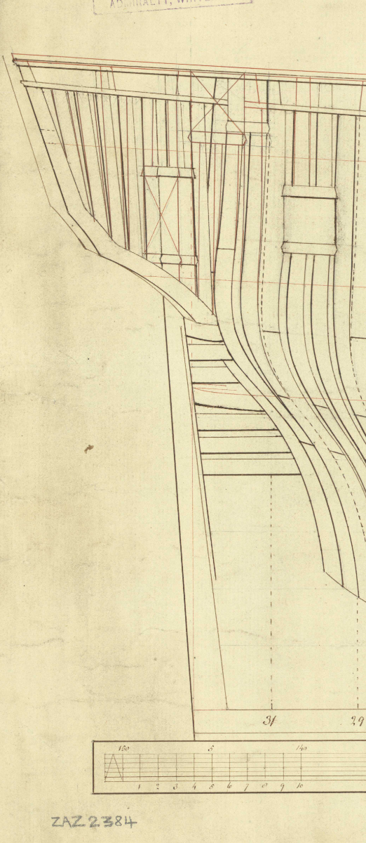
Hi David It is hard to tell, but did you taper the wales at the bow? They taper in thickness to match that of the other planking so they fit in the rabbet properly without having to make a notch as some folks do. Couple photos from Preble Hall follow. Hard to see but if you look closely you can see how the ends match the surrounding planks to fit into the rabbet. Allan
-
Are they internally stropped? I don't see any on their website. Those that I see on the website are not at all appropriate for a late 19th century fishing schooner that you mentioned was the subject vessel. Thanks, Allan
-
There are examples on the RMG Collections site. Several contemporary model examples https://www.rmg.co.uk/collections/objects/rmgc-object-66300 and https://www.rmg.co.uk/collections/objects/rmgc-object-66359, https://www.rmg.co.uk/collections/objects/rmgc-object-66325, https://www.rmg.co.uk/collections/objects/rmgc-object-66357 From Lee's Masting and Rigging of English Ships of War, page 184, the length of the ensign staff was 1/3 the length of the main mast above the taffrail and the diameter was 1/2 inch per 3 feet of length. The ensign staff tabernacle looks to be a bit thin in your photos in post #1 above. Looking at photos of contemporary models the tabernacles look to be closer to 10 or 12 inches deep. Not a big thing, just curious if anyone knows if there was some kind of standard for this. Are you going to rig the staff and hang an ensign? Allan
-
HMS SUSSEX by KarenM - FINISHED - 1:48
allanyed replied to KarenM's topic in - Build logs for subjects built 1501 - 1750
Thank you for the explanation, it is very much appreciated. Allan -
TOWTT - Your screen name made me think of the below photo on a cruise ship circa 1900. Super warm welcome to MSW. Allan
-
HMS SUSSEX by KarenM - FINISHED - 1:48
allanyed replied to KarenM's topic in - Build logs for subjects built 1501 - 1750
Beautiful work!!! Can you describe a little bit about your carving techniques and what type of tools and wood your are using? Where duplicates exist such as on the beakhead bulkhead and the wreaths around the ports, each piece looks identical to the other which is remarkable. Спасибо Карин Allan -
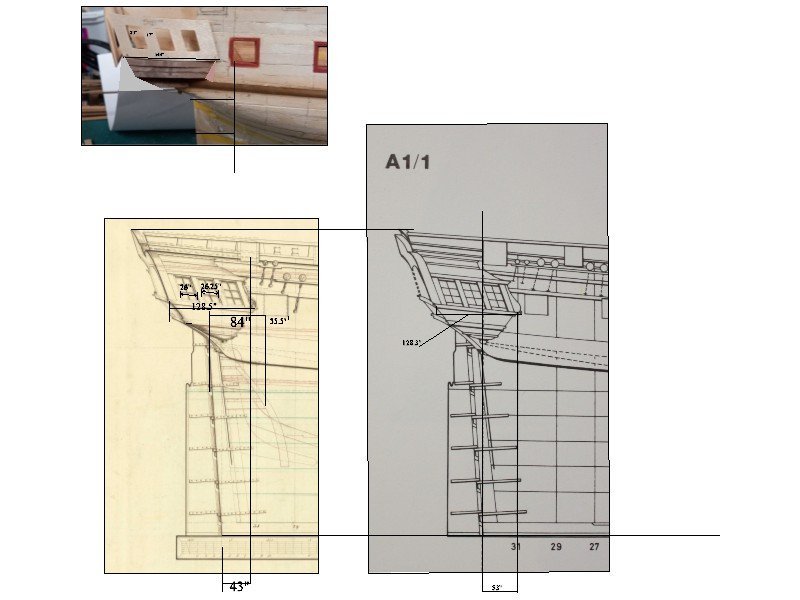
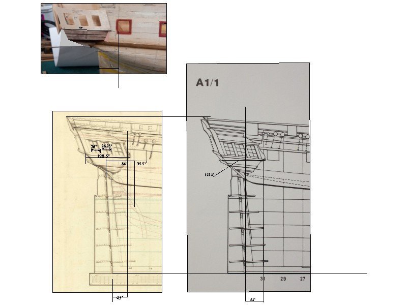
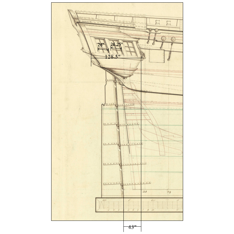
Sorry Dave but do you mean the 84" (I know it is hard to see on the small drawing attachment) which in THIS case is from the aft edge of the aft most gun port to the aft perpendicular which I believe is the aft side of the rudder post at the load water line. Cheers Allan
-
I scaled the drawing to 1:64 and get 17mm. IF the contemporary drawing is correct, it could be the kit got it wrong. I was curious to know what the AOTS book showed dimensionally so downloaded their drawing and compared. (Forgot I had that book 😕) There is a 10" difference between the AOTS and the drawing from 1774. Note that the widest part of the quarter gallery is the same on the original drawing and the AOTS drawing. Allan
-
Hi Dave FWIW, the scantlings in The Shipbuilder's Repository shows these ports for a 38 at 35" fore and aft and Steel's Elements and Practice of Naval Architecture gives them at 34" Further they both give the distance from the aft side of the after most port as being 7 feet 0 inches forward of the aft perpendicular. Even with these scantlings I would compare them to a contemporary as-built drawing or at least a contemporary design drawing or a contract. I would not rely on modern drawings without first comparing them to contemporary based drawings and/or scantlings. Once bitten, twice shy. Allan
-
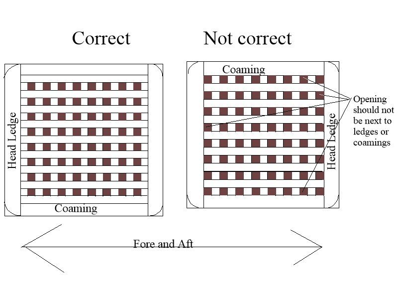
Yes, but originally the sketch was meant to also show open edges on one which is not correct, Sorry for the confusion. Thanks for pointing this out😀
- 341 replies
-
- 1
-

-
- Sophie
- Vanguard Models
- (and 1 more)
-
I got curious and inserted your photo into the drawing as well. The gun ports per the drawing should be 35.5" fore and aft. I sized your photo to match the gun port width of the drawing. Given that port dimension on your model is correct, the dimension I gave above of 128.5" looks to be closer to 144" on your model. The openings for the lights are 22" and the space between 17" compared to the 26" and 7" on the drawing. I am probably not making any sense, but maybe the below will help. I realize this is not accounting for the slight curve in the z axis, but should be pretty close IF the dimensions I am guessing at on the model photo are close. Sorry for the full size dimensions, but it is easier on the CAD drawing for me. Allan

-
David Sorry, I should have marked it better. I uploaded the drawing into CAD then scaled it to full size. The 25.5 inches is actually a slight mistake. I just re-measured and it should be closer to 26 inches. It is the width of the lights on the quarter galleries. Revised pic is below Allan
-
HMS SUSSEX by KarenM - FINISHED - 1:48
allanyed replied to KarenM's topic in - Build logs for subjects built 1501 - 1750
Thank you Karen, I wonder if the style on the museum model is atypical rather than a more common design. I can understand how the drawings were done by McArdle if he based them on the contemporary model. Again, your workmanship is outstanding. Allan -
HMS SUSSEX by KarenM - FINISHED - 1:48
allanyed replied to KarenM's topic in - Build logs for subjects built 1501 - 1750
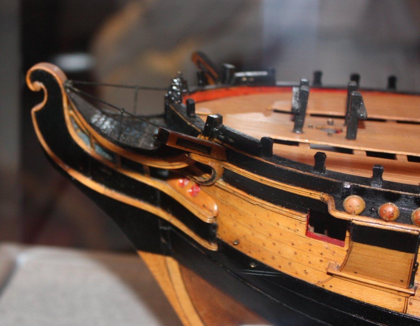
This is one of the finiest builds here at MSW, thank you very much for sharing with us. I have a question regarding the lights on the stern and the quarter galleries, there seem to be an inordinate amount of panes, 30 on each stern light, 25 on the quarter gallery lights. Was this actually done in this time period and if so, was it common? I cannot find any contemporary models or plans for the late 17th century showing more than three panes across or up and down. Photo of the contemporary model of Boyne (80) 1692 is below Thanks Allan1692.thumb.jpg.c3f400417f4bf837188aae4f4aee702f.jpg)
-
The gratings look nice but for future consideration keep in mind that the battens run fore and aft rather than athwartships.. Probably not a big deal to most folks, and they do look more realistic than metal etched. Enjoy your voyage to Maine!! Allan
- 341 replies
-
- 3
-
-
- Sophie
- Vanguard Models
- (and 1 more)
-
Hard to tell from the photos what is what dimensionally, but you are right it does look oversized. David, maybe the below will help. From RMG for Diana, Artois et al In the photos it seems the counters do not curve far enough forward. Might just be the angle of the photos. Pic at the QD is below to check. Allan


-
Glenn, What of the upper decks? 😀 If you do go with treenails, they really should be barely visible. Bamboo is easy to draw to very small diameter and is subtle in color. But, for 1:64 they should be about 0.011 to 0.015" (0.3mm to 0.4mm) Drill bits that small exist, but making treenails that small can be an exercise in futility. It is easier to just drill the holes then fill the holes with watered down white or yellow glue then sand the deck while the glue is still wet which will fill the holes. Small sections at a time are called for. Alternatively you can drill, sand and then spray a clear coat to keep the dust in the holes. Testing scrap pieces is of course a good idea if you have not done this before. Cheap bits are not worth the trouble, but good jobber bit prices may be prohibitive. It is easier for the hull as they have bigger treenails closer to 0.6mm diameter at 1:64. The downside is that there were well over 100 frames that would have been be treenailed so even if only in the areas not painted or coppered there are several thousand needed. Fun times!!! Allan
- 587 replies
-
- 1
-
-
- Indefatigable
- Vanguard Models
- (and 1 more)
-
Hi Glenn, At your scale it is a very nice change to see a fine job of planking that has not been ruined with stark out of scale trennals as seen in so many build logs. Less is more, and none is probably best. Allan
- 587 replies
-
- 2
-

-
-
- Indefatigable
- Vanguard Models
- (and 1 more)
-
Technical drawings & Dutch shell first
allanyed replied to Jules van Beek's topic in Nautical/Naval History
Best quote of the day!! -
It is so good to see such a well executed card model. After following Doris' build in years past, and now your build it is great to know card models are an alternative way to create a masterpiece. What is the material of the sails in the first photo? Thanks Allan
-
Regarding your builds for the Mayflower and Golden Hind, what do you mean by "set"? Cannon were not typically run out unless being used. If you want them as they would normally be sitting they would either be inboard with the muzzle of the barrels secured up against the bulwarks or sometimes the cannon were turned to lay next to the bulkheads in a fore and aft position. With the tight quarters and the passengers on Mayflower having only about 70 feet of deck space, having the cannon laying fore and aft against the bulkhead may make more sense. Many folks probably don't care but keep in mind that English cannon patterns and carriages in 1577 and 1620 were different than later patterns starting with the Browne and Pitt patterns in the 1627. Even the carriages were quite different. Small caliber cannon carriages such as those for minions and sakers that Mayflower carried sometimes only had two rolling trucks and the rigging was different than in later years. Allan
-
Great video Kevin What is extra nice is that you show the mistakes and explain what causes these and how to avoid them. Thanks for sharing. Allan
-
Thanks for posting this video Keith. VERY nicely done. Time to go to their earlier segments.😀 Allan


1692.jpg.d28ee15e4d83305b5101f98e83a4d909.jpg)