allanyed
-
Posts
8,149 -
Joined
-
Last visited
Content Type
Profiles
Forums
Gallery
Events
Everything posted by allanyed
-

Technical drawings & Dutch shell first
allanyed replied to Jules van Beek's topic in Nautical/Naval History
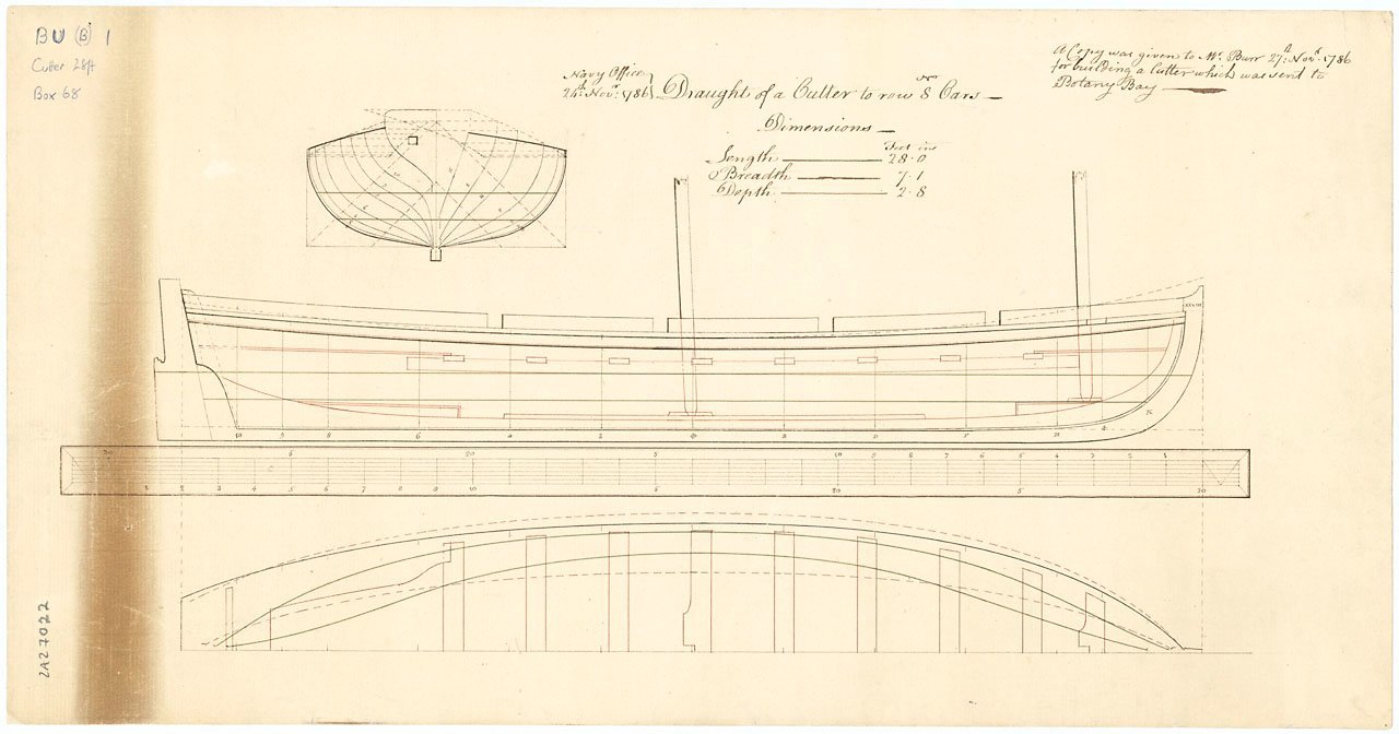
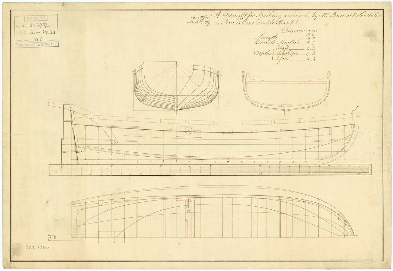
I hope you do not mind a disagreement on this as I think it is good to have a discussion like this. 😁. I have no idea what you mean by "normal" ship model drawings. Many of us use contemporary drawings, contracts when available and scantlings from the Establishments and elsewhere when appropriate. There are many small boat drawings showing the thwarts and tholes properly located including several below. Cheers Allan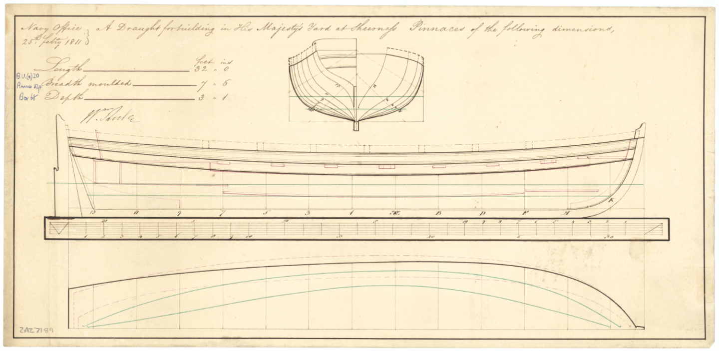
-
Technical drawings & Dutch shell first
allanyed replied to Jules van Beek's topic in Nautical/Naval History
Hi Jules I just inserted the plate of the 24 foot sloop of 1690 into a CAD program, brought it to full size using the scale. The dimensions are what they are, not my interpretation. Unlike the 24 foot sloop drawing, the Hohenzollern model looks realistic with evenly spaced thwarts and tholes. This thread is very interesting, thank you for posting it. Allan -
Totally agree. If done this way I have never had a problem sliding the rudder in place. A number of kits provide the hardware but some are way out of scale so may be this is part of the problem. You may find some useful information from the below example from the original contract for Elephant (74) 1786 for that particular size vessel. Picture and a 1000 words, etc. showing the rother of the Elephant below ROTHER The Rother-head to be made long enough to receive a Tiller above the Upper Deck, to be strapped and hooped with Iron as usual, to be 2 feet 2 inches Thwartships: Fore and Aft 2 feet 4 inches, and 5 feet 6 inches broad at the lower End, and 4 feet 6 inches at the lower Hance height above the Deck as the Draught shall Direct. To be well made, the Pieces tabled to each other, and all but the Main and Bearding Pieces, to be Fir. To have 7 Pair of Rother Irons, the upper brace to have long Straps, that may turn and meet round the Post. The second Brace 4 feet 6 inches long from the Rabbit, the lower one from the Back of the Post 7 feet; to be hung Flemish Fashion, and well secured with Chocks above Water to prevent its unhanging. The Pintles to be 3⅜ inches diameter, all of them to be 1 foot 1½ inches long, except the lower one, that to be 1 foot 3½ inches long; the Straps of the Rother Braces and Pintles to be 4½ inches broad, and 2 inches thick in the Shoulder of the Return, and to have an iron strap on the Back of the Rother, and a Ring Bolt with two Rings by 1⅞ inches diameter drove through the Rother; the Rings of sufficient bigness; and to have an Eye bolt on each Side at the Ends of the Wing Transom, with Bolts of 1¼ inches diameter for the Rother Tackles, that all, both Braces and Pintles be carefully let in, that the Irons bear an equal Strain, that every Pintle and Brace have Bolts in the strap as close to the Shoulder as may be, drove through with a Saucer-head, and well clenched on the other side, the hole for the Tiller in the Rotherhead to be cut both that above & below the Upper Deck of equal bigness, square on the foreside 11⅛ inch on the aft side 10 inches that the same Tiller may fit either hole. The Bearding of the Rother, between the Pintles and Back of the Stern Post, to be covered with Lead turned and nailed on the Sides; also to Lead the Helm Port, as is done in His Majesty’s Yards.

-
Technical drawings & Dutch shell first
allanyed replied to Jules van Beek's topic in Nautical/Naval History
Great picture Mark. The tholes look to be the same distance from the thwarts and alternate to set up for single banked rowing unlike the drawing above. A few inches is probably not unusual, but I cannot get my head around there being about 14 inches from one thwart to the tholes and another 30 inches. Allan -
Very good point about the line size. If you can squeeze double the line through the holes in the blocks the line is twice the circumference that it should be. In general most builders find that undersize is better looking than over size on ship models. Allan
-
Technical drawings & Dutch shell first
allanyed replied to Jules van Beek's topic in Nautical/Naval History
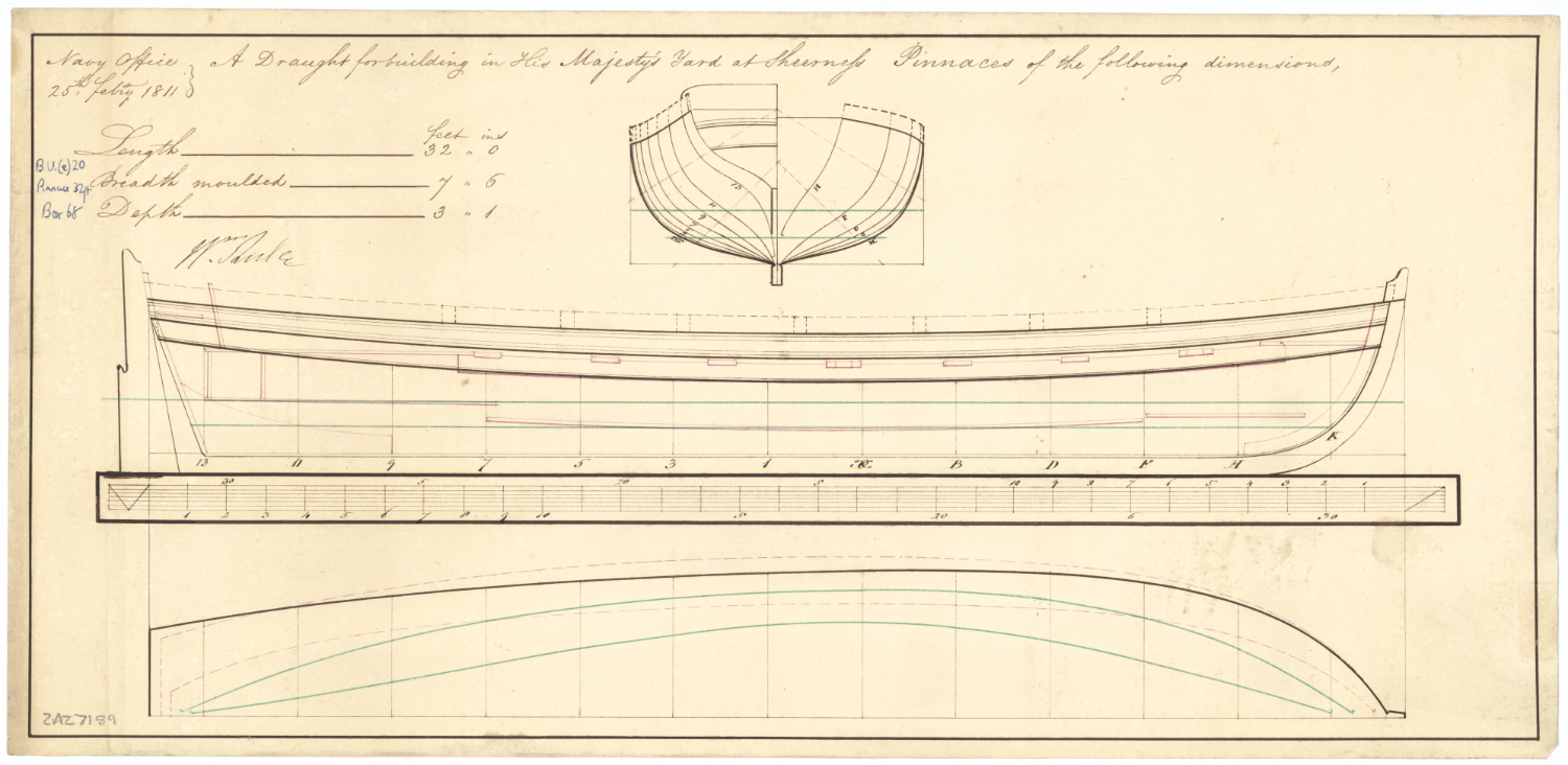
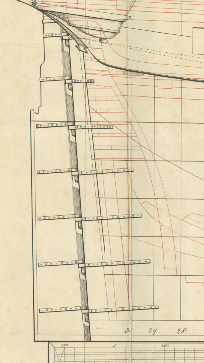
I just now read this topic and it is indeed interesting, thank you very much for sharing. I do question the knowledge of his father in at least one instance. In the below drawing ----the boat is wide enough to be double banked so it makes sense that there are openings in the gunnels for the oars to sit port and starboard. But, assuming the rowers were pulling oars as was normal they would be seated facing aft, how could they possibly row with the varying distances between oar placement and seating placement? Add to this that the aft most thwart has no openings in the gunnel at all. Maybe this was just an extra thwart for passengers. The distance varies from about 30" (a long reach for a rower) to 14", so no room to maneuver an oar at all without hitting the rower in front of him in the back. This is exaggerated in the aft most position as the openings are even with the thwart. It might just be me but this design makes no sense at all. Hope someone can explain things if I am missing something. Allan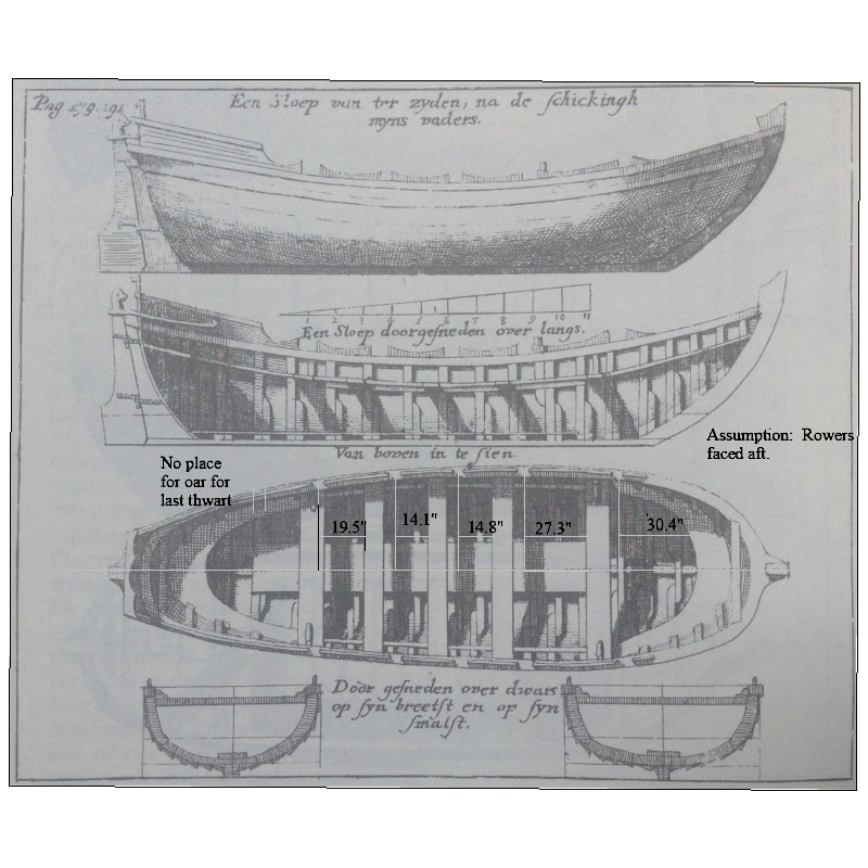
-
Amati/Victory Models HMS Vanguard, examples of natural wood finish?
allanyed replied to Esap's topic in Wood ship model kits
What kind of wood came with the kit? For the hull above the coppering Alaskan cedar and castello boxwood are popular and are very tight grained so look terrific when left natural. The wales and the strake above the main wales of course can be any wood as they would be painted/stained black. For items such as bitts and such, Swiss pear is a reddish color that may alleviate the need of red paint. Same goes for the stops in the ports, spirketting and quickwork on the bulwarks, although the red may be too subtle for you compared to what is usually seen on contemporary models. Rosewood, especially Brazilian rosewood, is a great red color wood, but needs to be wiped down with IPA or Xylene to remove the surface oil to eliminate the gluing issues. For decks, holly is grand and the whitish color gives a contrast to the other woods in the build. Allan -
Hi Gary Welcome to MSW!!! It would be very nice if you would please post a little intro about yourself in the new member forum. Please consider starting a build log as it will bring a lot of viewers and help if you wish to have it. In general, one of the most popular methods of threading rope through a block is to wet maybe a quarter inch or even half inch of the end of the rope with cyanoacrylate glue (liquid, not gel) then when cured, using a scalpel or even nail clippers, snip off a tiny piece of this stiffened portion, cutting on a bias, to create a point on what is now a needle of sorts. I realize this is your first build, but it is good to start with good habits and have useful information so I hope the following is not unwelcome. It sounds like the rope is too large or the hole in the block is too small in diameter. There were dozens of rope sizes on a given ship, but for modeling purposes 6 to 8 usually suffice for most folks. There are spread sheets by Danny Vadas available in the articles data base here at MSW that will give you every rope size of a wide range of British ship sizes and eras. Typically the circumference of the rope was 0.25 the size (length) of the respective common blocks. (Lees' Masting and Rigging of English Ships of War, page 189) Tiller rope was 0.25 the size of the main stay and the circumference of the main stay was 1/2 the diameter of the main mast. Note that rope sizes were given in circumference, not diameter, so you will have to convert when getting properly sized rope if you do not have any. The use of miniature rope in place of some, not all, kit supplied thread (which often looks nothing like rope,) will enhance your model a lot. Allan
-
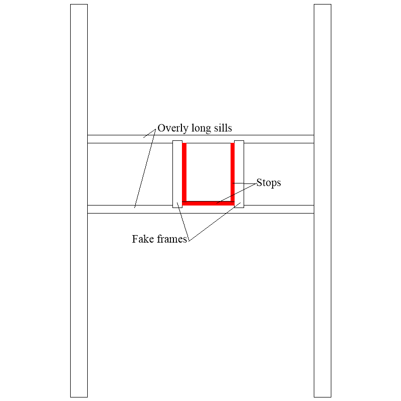
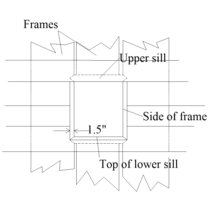
I have seen both on contemporary models but not sure why they did that. It has always been my understanding that there were no port lids where the ports were on open deck areas such as in the waste or on the QD and FC so there was no reason for having stops. I was indeed asking about the red lining areas which were actually edges of the frames and lower sill. I realize there always seems to be exceptions but the sketch below is what I was asking about, hope it is more clear than words. The first sketch is based on what I recently learned here at MSW and should be close to how these were done on the actual ships, and the second is closer to what can be done on a POB model. Allan
- 43 replies
-
- 2
-

-
- Essex
- Model Shipways
- (and 2 more)
-
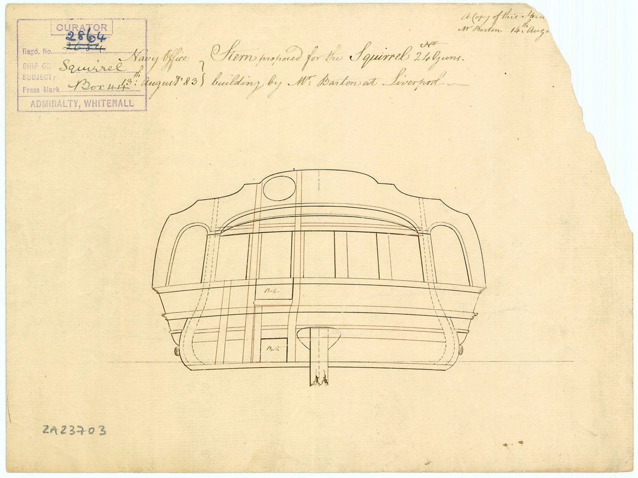
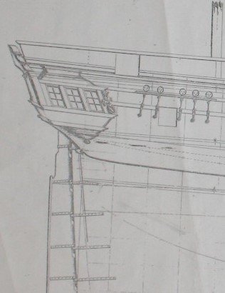
I found a few others as well and the quarter galleries seem to be more prevalent than the badges going back as far as 1715. Stern view and side view of a 24 gun that hopefully describes a little better. In addition, you are lucky as Greyhound was built to the 1719 Establishment and all the scantlings are readily available to help you on your project.
-
Hi Rick, Very neat work all around, kudos! Do you know if other US ships were planked to create stops at the upper sills of the gun ports as you show or was this peculiar to the Essex? I know RN ships typically did not create stops on top of the ports, just the sides and bottom, but I am unfamiliar with US ships. Thanks Allan
- 43 replies
-
- 1
-
-
- Essex
- Model Shipways
- (and 2 more)
-
Srenner The only thing that looks a little different for a quarter gallery in 1720 is the area at the level of the lights (what you call windows) as it curves back towards hull . The curve back would start at the level of the bottom of the lights, not above it at the time of Greyhound. Hard to describe in words so the pics posted above should help and maybe the one below. Actually would a 20 gun of 1720 have badges rather than quarter galleries?? Just curious. Allan
-
Charlie, unfortunately the answer to your last question is a little complex. Given 1774 as the date, on 4th rate and 5th rate ships there were likely truss pendants on the lower yards that were rigged differently in different eras plus they had the jeers with two pair of blocks, each pair having a single on the yard and a double on a sling over the cross trees. Sixth rates had two single and one double block, but in 1773 some were changed to have a jeer tie when this was reintroduced on ships of 28 guns and under. Note that parrels with trucks on the lower yards were superseded by truss pendants in 1760. The topsail yards would have had ties and two row truck parrels. Topgallants had a tie and truss parrel. There is a lot to this, and again it can all be found in The Masting & Rigging of English Ships of War. Way too much for me to copy and paste here while respecting copyrights. I am sorry to keep going back to Lees' book, but it does have a wealth of information. Allan
-
Thanks Patrick Based on comments from those who have tried this kind of adhesive, the kit maker may not be giving very good advice. I would hate to be looking at my model 10 years down the road and watch planks start popping loose!!! Allan
-
Hi Patrick, Sorry I must have misread the earlier post, I thought you went with contact cement. Others wrote that OcCre plans suggest using contact cement which seems a very odd thing to do if it is indeed such a bad choice for this kind of application. Was that the case in your kit as well? Regarding CA, I have never used it on planking models so cannot offer a solution. Have you tried to wipe it clean with acetone? As the wood in the kit is so open grained and porous, I hope the CA did not penetrate to the point that it cannot be removed. Looking at the photos you posted, it does not jump out to these old eyes. I can see that your planking looks exemplary! Allan
-
Hi Charlie Which Black Prince, there were a number of them? James Lees' The Masting & Rigging of English Ships of War gives a very detailed and complete order of dressing on pages 158-160, It covers from circa 1611 through circa 1860 as the order did change over time as the configuration of masts, spars, and rigging changed. If your particular model is the USS Alfred 1774 later renamed the Black Prince, the order of dressing likely would still apply. Regarding your questions regarding the shrouds, it depends. Again from Lees' book, this is described in great detail on page 42. For the most part the forward most shrouds are in pairs, that is two starboard, then two port, two starboard, two port and so on. The bight round the mast was between one and a quarter and one and a sixth the circumference of the mast head. If there was an odd number of shrouds, the swifter (the aft most shroud) was fitted round the mast head with an eye splice (center splice) as you describe. Hope this helps Allan
-
Your planking is extremely neat, but I hope you do not have problems with the glue as contact cement is reportedly short lived compared to other commonly used glues for wood. This came up on another post the other day so I did a bit of research. One of many similar comments that I read --- Over time, rubber cement loses its "stickiness." Items bonded with rubber cement will gradually just "let go" of each other. The adhesive does not simply evaporate; rather, it dries out and leaves a brittle residue where the pieces come apart. Allan
-
Welcome to MSW Igmar. I think the process of meticulous work is in our blood. My father was a master of pysanky (one of his eggs below) which is as detailed as our ship modeling. I hope to see some of your work posted here at MSW. Allan x

- 20 replies
-
- 11
-
-

-
I hope you do not have additional problems down the road. From doing a little research it SEEMS rubber contact cement is not highly recommended for anything permanent. One of many comments that I read --- Over time, rubber cement loses its "stickiness." Items bonded with rubber cement will gradually just "let go" of each other. The adhesive does not simply evaporate; rather, it dries out and leaves a brittle residue where the pieces come apart. Allan
-
Gun Port Hatches
allanyed replied to acaron41120's topic in Building, Framing, Planking and plating a ships hull and deck
The more I think about this, you may be right Druxey. The key word is as you wrote, neatly. Cutting back the planking on both sides and the bottom of many dozens of gun ports exactly 0.5mm or 0.75 depending on scale would be a real challenge. Allan -
Gun Port Hatches
allanyed replied to acaron41120's topic in Building, Framing, Planking and plating a ships hull and deck
Very well explained Mark, thank you. This would certainly be easier from a modeling standpoint as well as real world for POF. Allan -
Gun Port Hatches
allanyed replied to acaron41120's topic in Building, Framing, Planking and plating a ships hull and deck
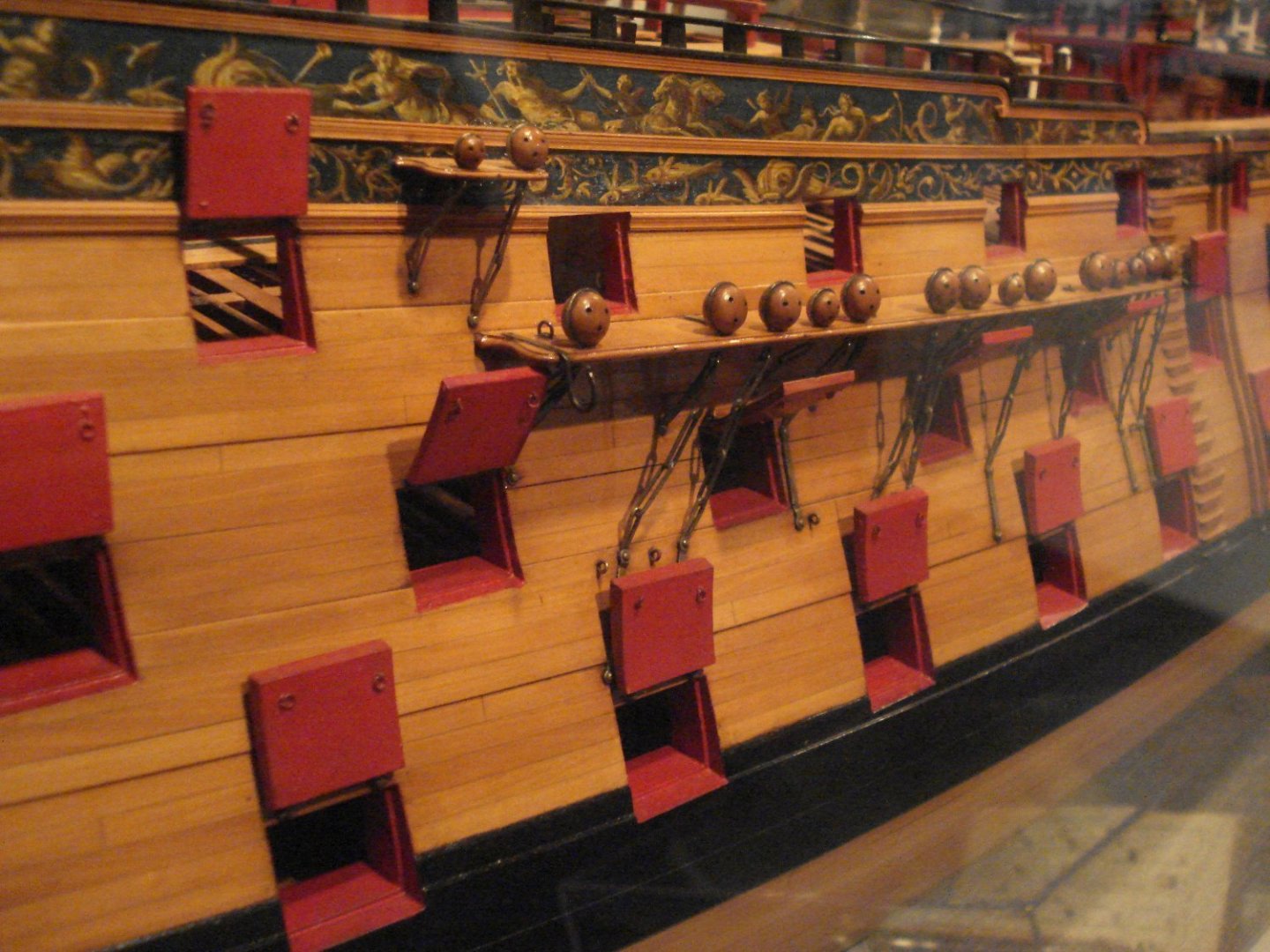
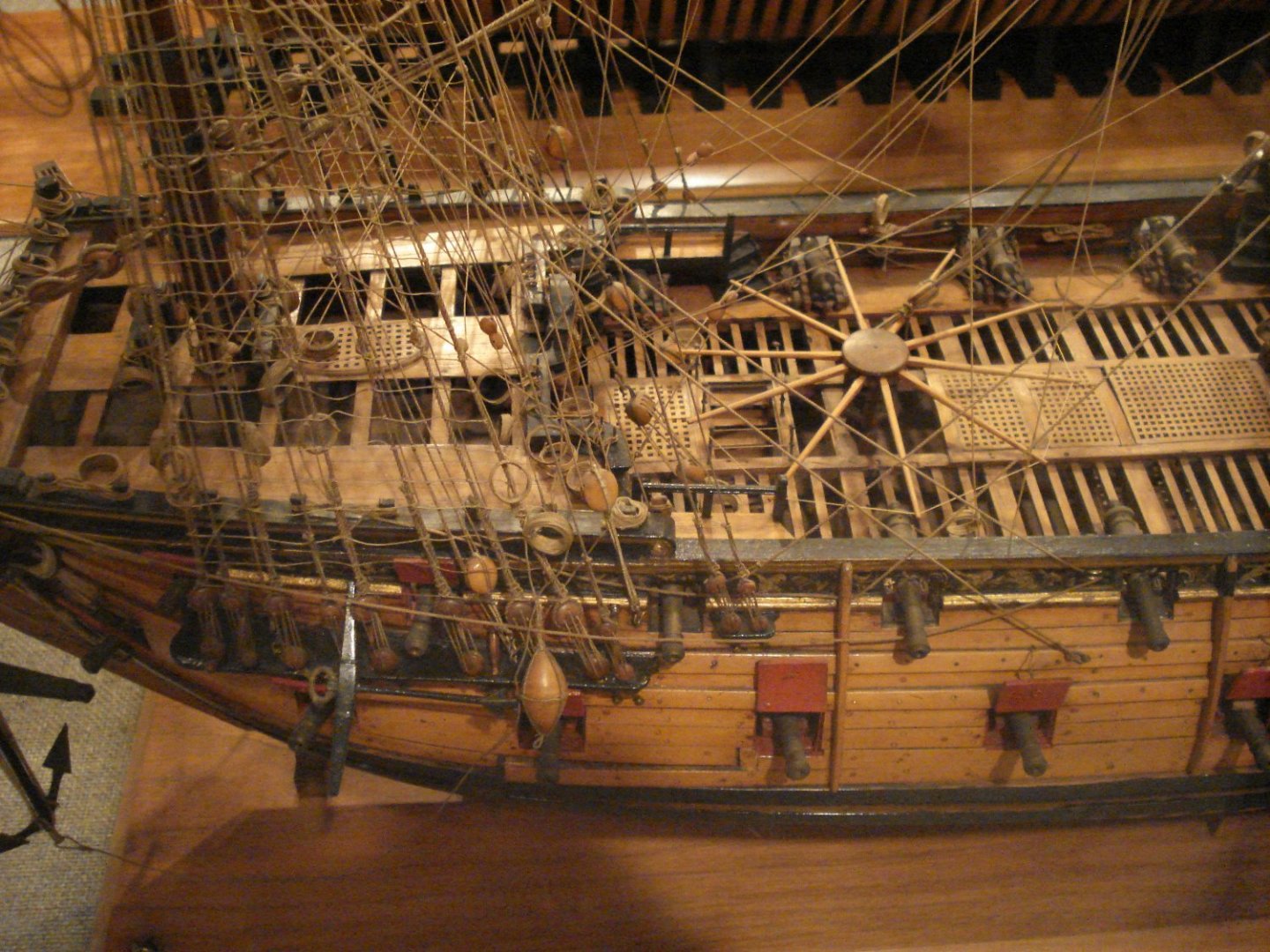
You can see the linings very clearly on a number of contemporary models. Note that the linings fayed to the frames rest on top the lining on the bottom sill. There are usually no linings on the top sill. Based on contemporary model, there are sometimes no linings in the ports which carried no lids such as those on the upper deck at the waste as in the third pic. Pics are from Preble Hall, Annapolis. Allan
-
Use the search tool and it makes things go quickly. I typed in a few key words and came up with a number of posts in Ed's build log, including #3079 that might be a good one for you. Allan
-
What are ground toes?
allanyed replied to allanyed's topic in Building, Framing, Planking and plating a ships hull and deck
Thanks for the feedback everyone. Craig, I know of TOCS but only in the sense of modern terms, the theory of constraints which is a management paradigm😁 Looking further at the "c's" and "e's" in the contract, it could very well be toc versus toe. Either way I am at a loss. It sounds like flying is new stuff and ground is used material which makes sense, but what exactly is toe, toc, tow? It really is not an issue for our model scales, but I did find it to be an interesting item none the less. Dean, To me the word looks nothing like tow, BUT, you may be right based on what I found when looking up TOW. MIddle English - touw from Old English tow (“spinning”) in compounds, e.g. towcraeft, towhus, towlic, from Old Norse tó (“uncleansed wool”), Dutch touw (rope) Bob Just saw your post after I wrote this, so my follow up post is a bit late, but maybe fits in with your dissertation which looks to be spot on. Thank you very much! Allan -
Thanks Keith. This model is way too big for our house but it still might be interesting to go see it. I will PM the person that posted. Allan