


allanyed
-
Posts
8,149 -
Joined
-
Last visited
Content Type
Profiles
Forums
Gallery
Events
Everything posted by allanyed
-
 Rio Congrats!! Am I correct in assuming you do not have a scroll saw or coping saw to cut them out yourself? I am pretty sure there are a number of folks here that will be interested in knowing how you do with laser cutting, including number of bulkheads you will be getting and total cost. Will you be using your paper plans or will you redraw them first? Thanks in advance. Allan
 -
EURYALUS 1803 by Peter6172 - 1:48
allanyed replied to Peter6172's topic in - Build logs for subjects built 1801 - 1850
So far, so (VERY) good!!! Just as an FYI, there is no margin line on any transom other than the wing transom. The margin line has to do with strip of molding that covers where the lower counter planks and hull planks meet. Allan -
Andrew If you want to scratch a boat, there are several build logs for a 23 foot launch that may give you some ideas. The methods can be applied to any boat and there are a lot of boat plans on line at RMG and the Wiki Commons site but if you are looking at boats for your Bounty build, these will apply. The one below is centered on the launch which Bligh used. modelshipworld.com/topic/33539-23-foot-launch-by-allanyed-bounty-late-18th-century/ If you are interested in the plans PM me. Allan
- 310 replies
-
- 1
-

-
- Diana
- Caldercraft
- (and 1 more)
-
Looks like a takeaway from a torture dungeon 😀
-
EURYALUS 1803 by Peter6172 - 1:48
allanyed replied to Peter6172's topic in - Build logs for subjects built 1801 - 1850
Don't forget to keep the margin line, which is about 3 or 4 inches, on the aft face of the wing transom, flat. Allan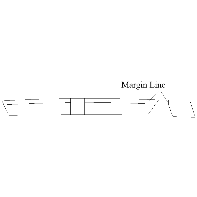
-
I remember seeing the intersection of branches and trunks, and roots at the stumps used for knees and the like but training bends in trees for frame parts was a new one for me. How on earth did they do that with an oak tree? For model size parts, apple orchards prune every year and have thousands of branches that are miniature versions of what the shipbuiilders harvested from the forests in full size. Pear and cherry would also work well. Not so sure about citrus. A few months in a dry basement or a day in a kiln then cut away to your heart's content. For smaller scales I found this to be tedious beyond belief, but for large scales like yours, it might worth the effort. Allan
-
Hi Chiomp What about the deck rounding? Decks other than the platforms and orlop were rounded as much as 9 inches depending on the deck and size of ship rather than lay flat. Allan ..............................................................................................................................................................................................................................Don't the bulkheads have rounding where the decks lie?
-
Syren. I would add rope as well as it looks like rope rather than thread. Allan
-
Looking for correctly scaled lines and rope
allanyed replied to Michael Smith's topic in Masting, rigging and sails
Do it before the striped bass start heading your way in the spring!😀 They caused me many a missed day in the ship model shop (and work) when they got down the shore. Allan -
It is very nice to see you continuing to amaze us in 2023!! Happy New Year Tiziano e per favore porgi i miei migliori saluti alla tua famiglia (please give my best to your family) Allan
-
Very happy to see you return to the fray Aiken Allan
-
EURYALUS 1803 by Peter6172 - 1:48
allanyed replied to Peter6172's topic in - Build logs for subjects built 1801 - 1850
I admire both your workmanship and courage in nearly starting from square one Peter Allan -
Perhaps speak with whoever had the sense to throw it to the curb. He may have it right, but then again, if monetary value is not a concern, perhaps to story behind it may have some value to share with friends and family. Allan
-
Hi Tim. I notice you have not marked the width of the strakes on the frames. How are you going to be able to know the strakes are the right width at each frame if they are not marked before hand? As you know the width is dynamic so if you do not taper the widths as needed there will be problems later. At your scale, probably every other frame should be marked. Tick strips are the easiest way to go. There is a detailed explanation in the Articles Data base here at MSW in the paper by David Antscherl. https://thenrg.org/resources/Documents/articles/APrimerOnPlanking.pdf I like your clamps. Allan
-
There are drawings of masts and spars from RMG in high resolution on the Wiki Commons site. Allan
-
Very cool! The most interesting thing I ever found when digging our veggie garden MANY years ago were three ceramic insulators and a racoon skeleton. Your find is WAYYYY better. Allan
- 11 replies
-
- 2
-
-
- Lowell Grand Banks Dory
- dory
- (and 2 more)
-
Thanks Mark, Now we have another challenge in our model making if we so choose, made spars to go with more commonly seen made masts. I doubt more than a small few will do this, but it would be interesting to see how they would make them at our scales and how well they turn out. Allan
-
Sorry I have no answer for your question regarding the frame height. But, I do have a question for you as you have piqued my curiosity. What is the object you are using as a weight in the photo. If you mentioned it already and I missed it, my apologies. Allan
- 11 replies
-
- 1
-
-
- Lowell Grand Banks Dory
- dory
- (and 2 more)
-
hello -old shipbuilder signing in for first time
allanyed replied to manning16's topic in New member Introductions
Welocme aboard John, It was a great pleasure chatting on the phone John, including my very minor and your major driving experiences in auto racing. I look forward to meeting at an upcoming Naples area club meeting. Allan -
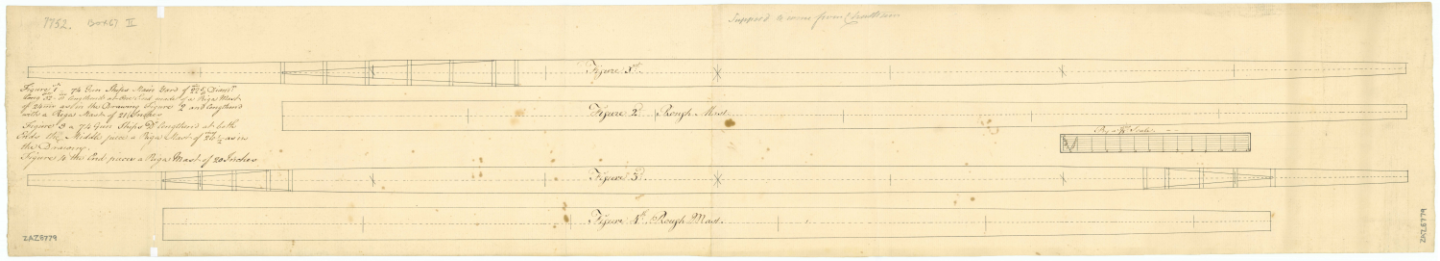
Until recently I have never seen a yard constructed of multiple pieces. The contemporary plan, figure #1, below has scarphed end pieces rather than a yard made of a single piece. It is from a British 74 gun ship of 1779. Does anyone know of other instances where this might have been common practice? At most common scales this would be visible but I have yet to see it on a contemporary or modern day model. I realize it is probably not of much importance for our scales, but I am curious about this. It is almost as if the legend on the left is mislabled as it calls it a main yard of 22 5/8" diameter TIA Allan
-
I am thoroughly enjoying your build log and your willingness to press forward when finding a problem! In order to avoid a confrontation with the Admiral if you happen to use HER hair dryer, there are industrial heat guns with a higher heat capability for $20 or less. (Don't overdo, it can burn the wood) Allan
-
Looking for correctly scaled lines and rope
allanyed replied to Michael Smith's topic in Masting, rigging and sails
For masts, spars, and rigging line sizes go to the spread sheet (based on David Lees' formulas) in the articles database here at MSW developed by Danny Vadas. Except for the period 1670-1710 it works very well. For that specific time period it is completely wrong and should not be used. Allan -
I thought you might find the below transcription of the original contract for the Elephant 1786 which was originally written in 1781 and which has the as-built scantlings that were added to the contract at time of her launching. Let me if it this doc file opens OK for you. If it does not, please feel free to PM me with your email address (mine is in my profile) and I can email it as an attachment as a doc or pdf Allan CONTRACT Elephant 74 gun 1781.docx
-
Welcome to MSW If you research Elephant 1786 at the RMG Collections site, there are a dozen low resolution contemporary plans including deck plans and inboard profile that you can use to get exact dimensions in all three axes. There is also a full set of high resolution drawings of 74's from the same period at the Wiki Commons site which includes Hannibal 1786, Venerable 1784, Victorious 1785, and Theseus 1786. Allan
-
Legos work in a lot of instances. Machinest squares work better in other cases. As for your situation Legos may not be well suited. I look forward to seeing your solution. As to examples, there are many hundreds of build logs here at MSW, some of which have photos of their building set up. They can be as sophisticated as that shown by Ed Tosti in his build logs or something simpler but using the same principals. If you spend some hours perusing the build logs you might find something you feel fits your needs. Look at the both scratch bulit and kit build logs. Allan
- 11 replies
-
- 2
-
-
- Lowell Grand Banks Dory
- dory
- (and 2 more)
