


allanyed
-
Posts
8,149 -
Joined
-
Last visited
Content Type
Profiles
Forums
Gallery
Events
Everything posted by allanyed
-
 I do the same thing, collecting saw dust from my thickness sander. I turn off the vacuum that collects the dust for a few passes then collect the dust in small jars for each species. I dab a little white PVA glue in the tiny gaps and push in some of the sawdust with a finger, let it dry, then sand. Is it perfect? Nah, but it does look MUCH better than those tiny slits. Is it easy to sand, yes, very easy, in my experience. Obviously, tight fights without those little gaps is best, but.........stuff happens. Allan
 -
Occre Diana (Spanish frigate 1792), low quarter gallery windows?
allanyed replied to Esap's topic in Wood ship model kits
Thanks, that is what I thought might be the case. The middle piece has three gallery lights, but they probably had no way to translate from Spanish to English so called them windows by mistake. Again, just a minor matter of nautical terminology which must be a very difficult thing for the folks making the instruction manual and drawings when it comes to translating. Thanks again Allan -
Occre Diana (Spanish frigate 1792), low quarter gallery windows?
allanyed replied to Esap's topic in Wood ship model kits
Do your instructions call these windows or something else? There are lights (not to be confused with lanterns) and ports but no windows on these ships. I realize this is a terminology thing so a very minor point to many folks, but I am curious. 😀. The translation from Spanish or Italian to English for many nautical terms has to be very difficult for kit makers as it is something of a language of its own. Allan -
Occre Diana (Spanish frigate 1792), low quarter gallery windows?
allanyed replied to Esap's topic in Wood ship model kits
The only way to know for sure is if you can find an image of the contemporary plans. OcCre probably based their plans on something, so maybe check with them or the Maritime Museum in Barcelona and the Naval Museum in Madrid to see what they have available. As with scratch building, research for kit builds is a good idea before plowing ahead. Allan Something to consider, but that is up to you in the end. Look at the various build logs here at MSW and compare to photos of contemporary models on the RMG Collections and other museum sites and you will be able to see which kits would approach what you are looking for. While the below is the HMS Diana 1794, not the Spanish ship, I suspect the gallery lights (windows) are closer to what would be the case even on the Spanish ship Diana Allan https://www.rmg.co.uk/collections/objects/rmgc-object-82174 -
FWIW, the Lettie Howard looks to have it as on the left. This of course is a modern photo so who knows if it is how things were done late 19th century. There are a bunch of photos of Ernestina (Effie M. Morrisey) on the Library of Congress website that may help as this is prior to reconstruction. The latest rebuild for Ernestina was recently finished at Bristol Marine in Booth Bay so they may have better information for you. Allan
-
Hi Doug, When the time comes, just as an FYI, if you have not seen it, there are two new build logs on the Bounty launch that may interest you in the scratch build forum. One is for a large scale, and the other for 1:48 (which can be changed for whatever is needed.) It is set up so anyone can build it with a minumum of tools. IF this is of interest, let me know and I can PM or email you (or anyone interested) the drawings at whatever scale you want. Allan
-
Hairy/fuzzy rigging thread
allanyed replied to The Gimps Chimp's topic in Masting, rigging and sails
I see this is your first post Ricky (apologies if I got the wrong R. Hortman), so welcome to MSW. Allan -
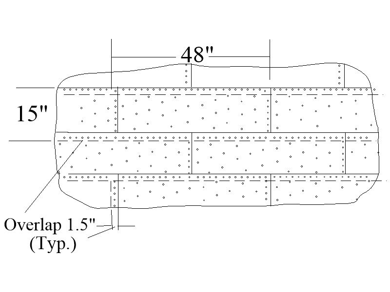
Hi Kiwiron, Lovely build, thank you for sharing your log. For future consideration note that actually the plates overlap 1 1/2", they never butted together. This might be difficult and may not look good with the kit plates as they look to be much too thick. At your scale they should only be about one to two thousandths thick so likely have no choice unless you go to copper foil which is a good choice. At your scale, nail dents (not raised bumps) would be barely visible. See the sketch below. (The copper paint looks very good by itself.) One point about which I am curious, hope you don't mind. Did the kit call for the port lid stops on all four sides? I am pretty sure Victory is like most ships of that era in that they were only on the bottom and sides of the port to keep the lid from swinging in.
-
Welcome aboard MSW VeeBee Hope you enjoy the voyage!!! Allan
-
Incredible work! Have you, or would you, consider doing a little YouTube video on your techniques or perhaps a video the moderators can use to add to the Articles data base here at MSW? Thanks Allan
-
Hi Henry, This seems about 100 years too early for jackstays. From David Lees' The Masting and Rigging British Ships of War 1625-1860, page 159 1811 Introduction of jackstays on the yards. Allan
-
Very happy to see you join this motley crew at MSW Tim Allan
-
All things considered, what you have achieved so far is very impressive!! Will you be planking the second later the same as the first layer? The tutorial on planking here in the Articles section and the Chuck Passaro video on planking are a tremendous help for anyone wanting realistic planking on their model rather than what some kits propose. When it comes time to build the launch that Bligh used (he did not use the jolly boat, it was rotted through) consider taking a look at the build log on making this launch yourself. https://modelshipworld.com/topic/33539-23-foot-launch-by-allanyed-bounty-late-18th-century/ I look forward to your next post Allan
-
Lyle, The model is looking really nice! I realize the launch on your ship is a kit conception, and not to steal your log, but for the future, if you or anyone is interested in this little vessel from the Bounty a lot has been discussed here lately at MSW in the Plans forum and maybe check out the following build log if you wish. modelshipworld.com/topic/33539-23-foot-launch-bounty-late-18th-century. Allan
-
Your photo needed more than a simple "like". Great pic!! Allan
-
I can attest to this situation being hair raising. Happened to us when we were out in our boat fishing for striped bass one Spring morning between Sandy Hook and the Verrazano Narrows Bridge. We were out of the shipping lane that comes down the Raritan Reach so we just sat ---- untl we heard thunder. We pulled anchor to run for shore. Which way??? The compass showed us our heading. (Of course the GPS made it even easier😁) Still a scary situation.
-
David, You would only be dumb if you have a question and fail to ask it. For me, it seems we too often forget to ask those questions or do even a modicum of research before plunging ahead. Ask away!!!! Allan
-
Greetings from North Carolina
allanyed replied to PostCaptainAubrey's topic in New member Introductions
Welcome aboard and good luck on your project. Allan -
Further to what Gregory posted, it is my understanding that the binnacle was not a permanent structure but rather was lashed down when in use and was put out of the way when not in use so not shown on contemorary plans. I also wonder if it was not stowed when preparing for battle to protect it from damage or, at times such as Gregory mentioned. Up to three binnacles, (or abitacli, or habitacles) were carried at times but by order of the Admiralty this was reduced to two in 1779 unless demanded by flag officers. In these cases it is not clear where these additional units were kept, possibly below as spares. If you study some contemporary plans you will usually see the capstans and wheel hub, but not the binnacle. I just took a quick look at about 50 profiles and inboard profiles and only saw one structure that might be a binnacle. Look at ZAZ3401 at the RMG Collections site, HMS Coventry 1757, et al. There is something just forward of the wheel that MAY be a binnacle. A high res plan can be seen at https://upload.wikimedia.org/wikipedia/commons/8/8b/Coventry_(1757)%2C_Lizard_(1757)%2CLiverpool_(1757)%2C_Maidstone_(1758)%2C_Acteon_(1757)%2C_Shannon_(1757)%2C_Levant_(1757)%2C_Cerberus_(1757)%2C_Griffin_(1757)%2C_Hussar_(1757)%2C_Bureas_(1757)%2C_Trent_(1757)_RMG_J6339.png Whatever this object is, it is not shown on the deck plans, so might be temporarily in place, thus the binnacle. Hope others have more information to share. Allan
-
EURYALUS 1803 by Peter6172 - 1:48
allanyed replied to Peter6172's topic in - Build logs for subjects built 1801 - 1850
Thank you for mentioning the need to taper this. The failure to taper the knee of the head both vertically and fore and aft is one of those things that seems to be prevalent but so easy to fix. -
I am basing this on the drawings we have been using as they show only one mast. Maybe she was built to have two masts originally, but then these drawings are open to question and possibly not reliable in other respects. The logs etc. indicate two masts but the drawings supposedly included in the Bligh papers show only one. Very confusing, at least to me. There is a lot of misinformation, including the modern models at RMG. Another example is at https://historycollection.com/the-mutinous-voyage-of-william-bligh-and-the-bountys-launch/8/ He posts a plan showing one mast but then goes on to say in the very first sentence that the launch had two masts. Allan
-
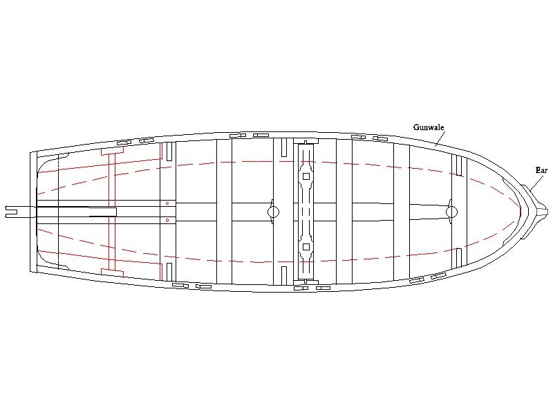
Hi Roger, No argument from me on that at all. That said, the lines such as stays and shrouds may still be valid. In addition I have played with the rig holding up the yard as alternative to the yard having a parrel and halyard reeving over a sheave within the mast. I have drawn both versions but not sure which was most likely used in this case. I am good with either choice unless if I can a find more definitive information. Lavery mentions that the shrouds were for stresses from both the sides and aft on page 227 of The Arming and Fitting of English Ships of War and "forestays braced the mast against pressures from forward on page 228." He makes no mention of backstays, so that question that I had seems to be answered. This may very well have been the case but as the launch was single masted when built, then modified during the Bounty voyage to the South Pacific, it has not been possible to find if the masts were farther apart or not. I show it about 6 inches aft of midships. The basis I used was a two masted cutter drawing ZAZ7022 of 1786. The aft mast is just about dead center along her length. Note that in this plan the forward mast is only about 10% of her overall length aft of the bow where as the launch original mast was 18% of the overall length aft of the bow. I have no idea if this played a factor in locating the aft mast. Also Lavery shows a photo on page 217 where the masts are separated by only two thwarts between the two that support the masts as I have shown. I realize this is a cutter in his photo, but the spacing principals may still apply. In any case the below is what I have come up with for now. Again, any definitive information to the contrary on any of the above is MOST welcome. Thanks for everyone's input, it is greatly appreciated. Allan
-
EURYALUS 1803 by Peter6172 - 1:48
allanyed replied to Peter6172's topic in - Build logs for subjects built 1801 - 1850
I totally agree with Giampiero, the build log from Matiz is awesome. For other templates, you can try to scan a part on a drawing then print it on label paper rather than using plain paper and glue. If you are missing any drawings or other information from the books with the transfer from Russell, feel free to PM Wayne or me. Allan -
Craig, The only reference as to length is Bligh's request to replace the 20 foot launch with a 23 foot launch. The plans you and I have been referencing are for 23 foot launches and they do fit the time frame. Roger, I agree that back stays may not be needed, but stays leading forward?? There is so little contemporary information on boat rigging that guesses are not unusual for us. The only detailed contemporary model I can find that is rigged is the Medway long boat. RMG has modern models as well but I have my doubts as to their accuracy. I have yet to find a detailed contemporary rigging plan and would sure welcome one! Thanks guys. Allan

