


allanyed
-
Posts
8,149 -
Joined
-
Last visited
Content Type
Profiles
Forums
Gallery
Events
Everything posted by allanyed
-
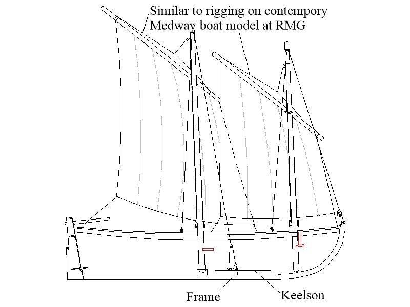
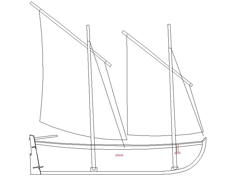
A little more detail has been added. Thoughts? The two indicated lines had me in a quandry until I studied the photos of the Medway boat model at RMG. I am still debating if there would be a single shroud for each mast on each side, or two as on the Medway model. Thanks!! Allan
-

Planking improvement
allanyed replied to Picard's topic in Building, Framing, Planking and plating a ships hull and deck
Did you bevel the frames before planking? If so, it looks like the plank above the one with the left red arrow is not seated completely against the bulkhead. I have found that soaking the plank thoroughly then clamping it to the frames without glue works well. Be sure the clamps have soft faces or put a piece of cardboard or soft wood between the wet plank and face of the clamp to prevent denting the plank. Then, heat it with a hot air gun for a minute or two. (Her hair dryer will work, but there are consequences if you get caught.) Once done you can remove the plank and it will hold the shape. Then you can glue it in place with finger pressure, no clamps. This will help assure the plank is seated well. Be sure it is completely dry as it will be expanded while wet, then shrink once dry. Alternatively, spile the planks. There is an excellent tutorial on here in the MSW articles data base by David Antscherl on how to do this. I find this a much better way to shape the planks for harder wood species. If your build is a kit, you will have to get sheet stock as you cannot use strip wood to spile a plank. Allan -
Exactly what I was contemplating Eberhard, Thanks again! Allan
-
LIke below? Thanks Eberhard Allan
-
Very neatly done planking Malcom. Also very inventive on the salt water corrosion!! Regarding the copper sheathing, unlike instructions in some kits, the plates should be installed so there are dents showing, not bumps as they were nailed to the hull, not riveted or bolted and they overlapped by 1.5 inches much like roof shingles. Just as an FYI for future builds, the actual plates were typically 15" X 48" and about 0.03 thick, thus 0.23"X0.75" and less than 1/1000th thick at your scale. A lot of modelers use copper tape as it is close to scale thickness and can be properly overlapped. AL has come out with a pinwheel punch to mark copper tape with nail dents. It is set up for 1/72 scale, so not to far off for 1/64. Looking forward to your future posts. Allan
-
Your build continues to be exceptional. One small thing that comes up on occasion, and I for one have not resolved in my own mind is the gun rigging. According to Adrian Caruana in volume II of The History of English Sea Ordnance 1715-1815 page 386, cannon on British vessels smaller than 32 pounders used two single blocks, not a single and double for the running out tackle. Same for the train tackle. I realize from the pics in your post #43, the drawing showd otherwise. Plate VII in the Universal Dictionary of the Marine, by William Falconer seems to show the upper deck guns with what looks like a single and double and these would be guns smaller than 32's being on the upper deck. Caruana shows a portion of this same plate on page 386 as well so it does not seem to be clear, at least to me. Is it likely that different blocks were used on different ships or was there a rule regarding the blocks? Hopefully a member can shed more light on this. Thanks for sharing your build with us. Allan
-
Sorry I cannot help in your quest, but please accept a warm welcome to MSW BG. Please post an intro about yourself in the new member section, it may generate more responses. Allan
-
Welcome to MSW Charlie!! Great having you aboard. Allan
-
Hi Srenner If you find that this kit does not suit you there are high quality kits from which to choose. If you think 20 guns are boring, what happens when you get to a first rate?😀 Consider studying some of the thousands of photos of contemporary models at the RMG collections site and you will see they do not always include the cannon, and when they do, they are often rigged with only the breach line or nothing at all. One of many examples of a sixth rate can be found at: https://www.rmg.co.uk/collections/objects/rmgc-object-66518 Good luck with your endeavors, it should be fun and rewarding. Allan
-
Prize Papers lecture from the National Archives, U.K.
allanyed replied to druxey's topic in Nautical/Naval History
That link takes me to my Yahoo account. Hope there is a good link as this sound interesting!! -
Your comment brought up an interesting point. What was the smallest ship in the RN considered a ship of the line. I thought a ship of the line was a fourth rate or larger but could be dead wrong on this. Not the most important piece of info in the world, just curious. Thanks Allan
-
Thank you for presenting this. It is good to see plates with nail detents instead of raised rivet-like bumps. Will you be making this tool for other scales? As the plates were typically 48" X 15", this appears to be made for models at about 1:72 scale. Thanks
-
I THINK he is referring to the fact that the topgallant yard on a model is not heavy enough to stay down and in position easily where as on a ship, it is. Allan
-
1:16, now that will be awesome. I would love to go that route, but I was thinking the 1:48 or even 1:64 would be useful to some folks needing a boat for their ship. 1:16.....hmmmmm, sounds like a fun project with the details you will be able to achieve. Now I am having second thoughts, but for a pinnace or longboat. FUN TIMES!!😀
-
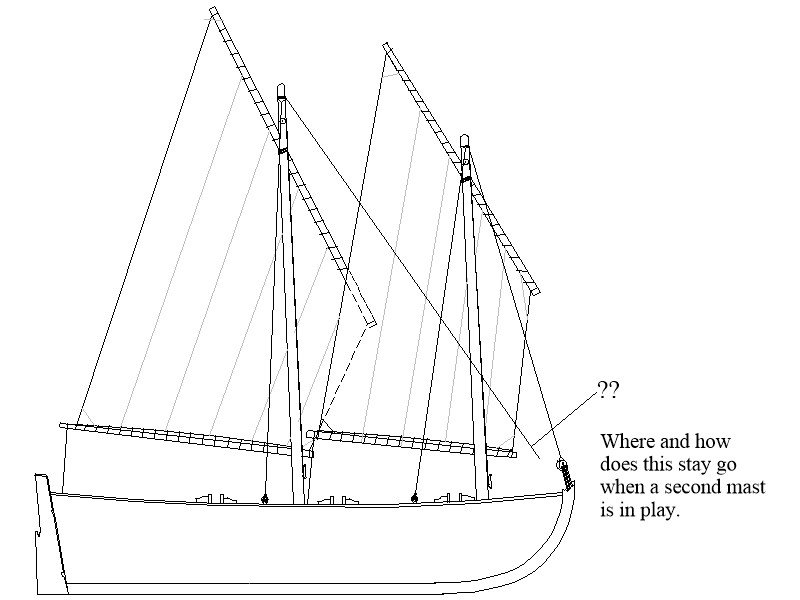
Contemporary drawings show three holes for which the forestay is rigged. When a second mast is present, how would the stay be rigged? Sketch below explains better than words, I hope. Allan
-
Your thoughtfullness to post the drawings is encouraging me (and hopefully others) to do the same. In my case, I am working on the 23 foot launch again. Two methods have been tried, the second keeping in mind folks with only a modicum of tools that can still do a scratch build in any scale. Drawings are done, and the second build method is about half way home. Allan
-
This continues to be a fun journey BE!!! Oars are some of the trickiest things to make, at least in my own experience. Laser cut means only shaping so a big plus versus making from scratch. I mostly use David Steel's scantlings for barge oars as well as for other ships' boats and wonder how they compare with what comes with the kit. Allan
- 106 replies
-
- 3
-

-
- Admirals Barge
- Vanguard Models
- (and 1 more)
-
Welcome to MSW Botra You have 43,000 new friends and helpers here to share their thoughts on everything from what tools to buy or avoid, kits to buy or avoid, recommended books and more Your comment on reading everything you can here will help you alot. Allan
-
I agree, more illustrations would be helpful, but what is there is beyond any other book as there are drawings showing the differences for each era. Unfortunately no book I have found has an abundance of belaying information. I wonder if this is due to the fact that each ship seemed to have some differences based on what the sailing master and/or captain and others preferred. Studying appropriate a contemporary model is very helpful as Petersson did, but having access to them is not usually possible for the majority of us. Maybe some member with access to a slew of contemproary models of different periods can put together a book, The Ultimate Book on Belaying Points! Allan
-
The list Gregoy gives is super. Keep in mind Rigging Period Ship Models is based on one contemporary model so somewhat limited. It is applicable to other ships, but.... Lees book is excellent and is applicable to over 200 years of rigging. It is highly detailed and worth the investment. If you are interested in modeling a ship built from 1600 to 1720, Anderson's book The Rigging of Ships in the Days of the Spritsail Topmast is a great addition to your library as well. No matter kit or scratch, a good reference book on rigging is very important. Allan
-
How to Seize a Block to a Sail Peak
allanyed replied to Yorky1's topic in Masting, rigging and sails
This is a fantastic post with the response from Phil Watson that you have shared with us. VERY COOL. Allan -
Thanks Gregory! I missed her when down loading the high res drawings from the Wiki Commons list into folders. These folders are set up by number of guns and misc. folders such as bomb vessels, boats, etc. I would love to share but there are over 40GB. MSW expressed an interest to set up a file for all members to access but other priorities over the past year or so have prevented this being done. If there is an easy way to do this for free, I would love to know so these can be shared. I have added contracts to the folders where appropriate and low res plans if a set was incomplete for a given vessel. Allan
-
Out of curiousity, which Rattlesnake is your model? There were several in the RN and two in the USN. (1780 and 1813) Thanks Allan
-
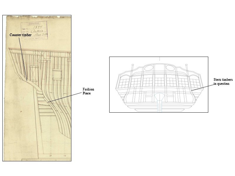
Those are counter timbers. Fashion piece is the aft most frame to which some of the transoms fay. I don't know the shape for Rattlesnake, but they look like the below on most ships. I think the buldges down low are less pronounced on Rattlesnake based on the dashed lines on the drawing you posted. Allan
-
J As you are more or less in the beginning stages, seriously consider the three vessel series designed by David Antscherl available from Model Shipways. They will teach a lot skills that will be used in your scratch build adventures. https://modelexpo-online.com/Model-Shipways-Shipwright-3-Kit-Combo-Series_p_5465.html Allan
