HOLIDAY DONATION DRIVE - SUPPORT MSW - DO YOUR PART TO KEEP THIS GREAT FORUM GOING! (Only 72 donations so far out of 49,000 members - Can we at least get 100? C'mon guys!)
×


allanyed
-
Posts
8,149 -
Joined
-
Last visited
Content Type
Profiles
Forums
Gallery
Events
Everything posted by allanyed
-
 Welcome to MSW. You can make a simple jig fixture to hold everything straight while assembling the various parts. It can be set up so you can take the boat out of the fixture to glue on a part, then back into the fixture to hold everything true while the glue dries. Allan
- 11 replies
-
- 2
-

-
- Lowell Grand Banks Dory
- dory
- (and 2 more)
-
Very well done model BE. Your research time has paid off to be sure, including the work you put into the shape of the oars. Great job!! Allan
- 106 replies
-
- 5
-
-

-
- Admirals Barge
- Vanguard Models
- (and 1 more)
-
Looking for correctly scaled lines and rope
allanyed replied to Michael Smith's topic in Masting, rigging and sails
The gurus of micro scales may be of help, especially including wire rope as Bob has mentioned. If you find a used copy of a book by Donald McNarry and or Lloyd McCaffery these may be of a big help for you. There are copies on the cheap on line. The rope is one thing, making to-scale realistic looking blocks at that scale is another challenge in which they delve. Allan -
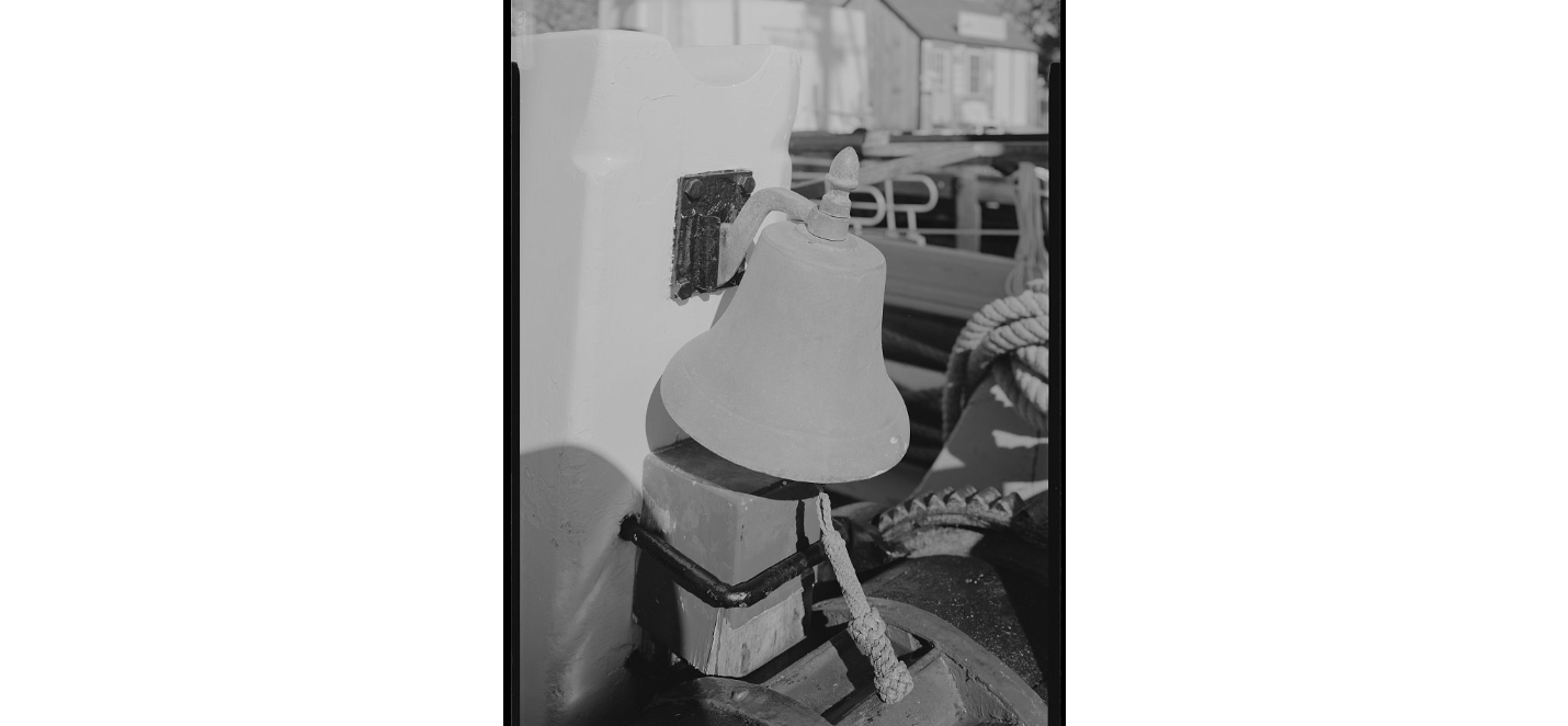
I did a quick search of contemporary cutter models and cannot find any with a bell. I am sure they were there, but they are not on any of the models or contemporary plans that I found so the world may indeed be your oyster on this one. I do see the bells on schooners including on the post at the windlass on the Effie M. Morrisey which was launched in 1894 so may be a good example for your RN cutter. Allan
-
Probably a bit late, but do you have the following photo from RMG? https://www.rmg.co.uk/collections/objects/rmgc-object-66464 Allan
-
Hello from Southeast Michigan, USA
allanyed replied to DonBMichigan's topic in New member Introductions
You could not have a better way to start into the hobby. Learn from these and the experiences can be applied to other kits that are more complex but may not be as well designed as these. Another plus is that these tricks of the trade will apply to many aspects of scratch builds if that is the road you will be taking. Welcome to MSW! Allan -
There are more than 20 low resolution contemporary plans of Diana 1794 at RMG Collections as well as a contemporary model. You may want to download these and compare to the AOTS book to look for any differences that might be there. https://www.rmg.co.uk/collections/objects/search/Diana plans 1794 Seven of these plans can be found in high resolution on the Wiki Commons site and are downloadable for free. I think they are on pages 4 and 5 and labeled as Artois. These are more than likely applicable to any of the Artois class 38 gun ship, including Diana 1794 as pointed out on the RMG site which lists eight of the nine the ships of the class on each plan description. https://commons.wikimedia.org/wiki/Category:Ship_plans_of_the_Royal_Museums_Greenwich You might also find it a good idea to use these contemporary plans as you can have them printed at any scale you want on single large sheets. Allan
-
Hi Patrick Very neatly done. It seems odd to me to see a two butt shift pattern, rather 3 or 4. Is this a kit convention or were you able to find this in a contemporary source? Thanks for sharing your build with us. Allan
-
Welcome to MSW J Please post a little intro in the new member section. You might get a few more responses to your query as well. Not sure what you mean on this. Could you post a photo with arrows or some such pointing out your concern? Looking at the photos of other build logs that Chris noted in his post there does not seem to be any problem. The keel piece does extend high up but the tops of the frames which look to represent top timbers that will have the bulwark planking looks right to me although the moulded dimension appears to be much to large. The top of the top timbers would be in the neighborhood of 2", perhaps, 3" (~0.04" at 1:60 scale) Allan
-
Regarding boats, there are several new build logs here in the scratch build forum for building a 23 foot launch (from the Bounty archives). The methods can be used for any boat, just need to use different plans to start which can be found at RMG Collections. I big array of power tools is not required, and actually can be done with small tools, either power or hand tools. I am guessing, but based on May's book on boats, Beagle likely carried at least three boats, maybe four or even five, including a 26 foot launch, 23 foot pinnace and two cutters, probably a 24 foot and 18 foot. These can be fun projects in themselves. Allan
-
Very good advice and maybe this should be carried even further. Check everything against contemporary plans and models of the Beagle or other similar brigs of the same era if they are available to see what the kit provides and what you might want to change to something more realistic. I am not talking about historical accuracy as everyone seems to have a different opinion of its relative importance, but little things like bowling pins used as belaying pins, realistic sails, realistic boats, et al. The AOTS book on the Beagle by Karl Marquardt should be a great help as well. Allan
-
A critique includes postives and negatives and many folks do not take kindly to the negatives so a lot of the more experienced builders avoid saying anything to avoid repercussions. Allan
- 43 replies
-
- 1
-
-
- Lowell Grand Banks Dory
- Model Shipways
- (and 2 more)
-
A belated welcome to MSW. It would be a nice thing if you posted an introduction about yourself in the new member forum and definitely mention your current build. It may lead more members to your build log. Look at the bottom of the main page as it shows the number of members as well as the number that are on the site at any given time. There are usually several hundred and as many as 2000 or more. Also, look at the number of views your log has had which is shown next to your build log name in the build log forum. You have already had 125 views of your build log. It may just be that no one had an answer at that moment, and as pointed out by Druxey, the holidays find many members with higher priorities such as family activities. Remember that patience is perhaps the most important personal characteristics one requires to be a successful ship model builder. That said we all have our moments 😀 Again, welcome to MSW Allan
- 43 replies
-
- 3
-
-
- Lowell Grand Banks Dory
- Model Shipways
- (and 2 more)
-
Got it, thanks! What confused me was that rather than round house or poop you mentioned "upper deck" which cannot be seen in that photo. Just another case of terminology confusion, not a biggie. Thanks again Allan
-
Welcome to our motley crew Andy. Hope to see you start a build log. As a POF newbie you are in a great place to learn from others' trials and tribulations in this endeavor. Allan
-
Recommended pins for planking?
allanyed replied to Capella's topic in Modeling tools and Workshop Equipment
If you pre-shape the plank by spiling or heat and edge bending, finger pressure and PVA (or CA if you choose) for less than a minute is all you need MOST of the time. Clamps certainly come into play at times, but if the plank is shaped beforehand, pins and clamps are not usually needed. Scale matters as well. If you are building at 1:48, the pin hole should be the same as a trennal, about 0.03". At 1:96 it would be 0.015. Trennals would then fill the hole, but at scales smaller than 1:64, they are extremely difficullt to make to scale, even using bamboo. Allan -
As mentioned above the species will dictate the amount of time needed to saturate the wood, not to mention how thick the piece is. If I am not spiling a plank I use room temp water then form ala Chuck Passaro method or right on the framing with clamps. A hot air gun works much better for me than an iron. A minute or two is sufficient, then remove the plank from the framing or formers and let it sit for a while to be sure it is thoroughly dry as it will have expanded while wet and will shrink again when dry. Hot air guns are cheap and get plenty hot (compared to the admiral's hair dryer) Spiling eliminates a lot of this if you want to go that route, especially for harder species. Allan
-
New to ship modelling? But what do you build first?
allanyed replied to MSW's topic in Wood ship model kits
Your model is a testament to your abilities as well as what a top quality, well designed, kit can yield. Kudos to you and Chuck both. Allan -
Hi Yves The majority of us do this from time to time, you certainly are not alone. I have spent hours searching for the right word even knowing I had used it previously but forgot what the word was. Windows instead of lights, thick instead of moulded, the list goes on. I am curious though about the beam you mentioned on the forward part of the upper deck. I just can't find anything like what you describe in the above photos of the contemporary models. Thanks again! Allan
-
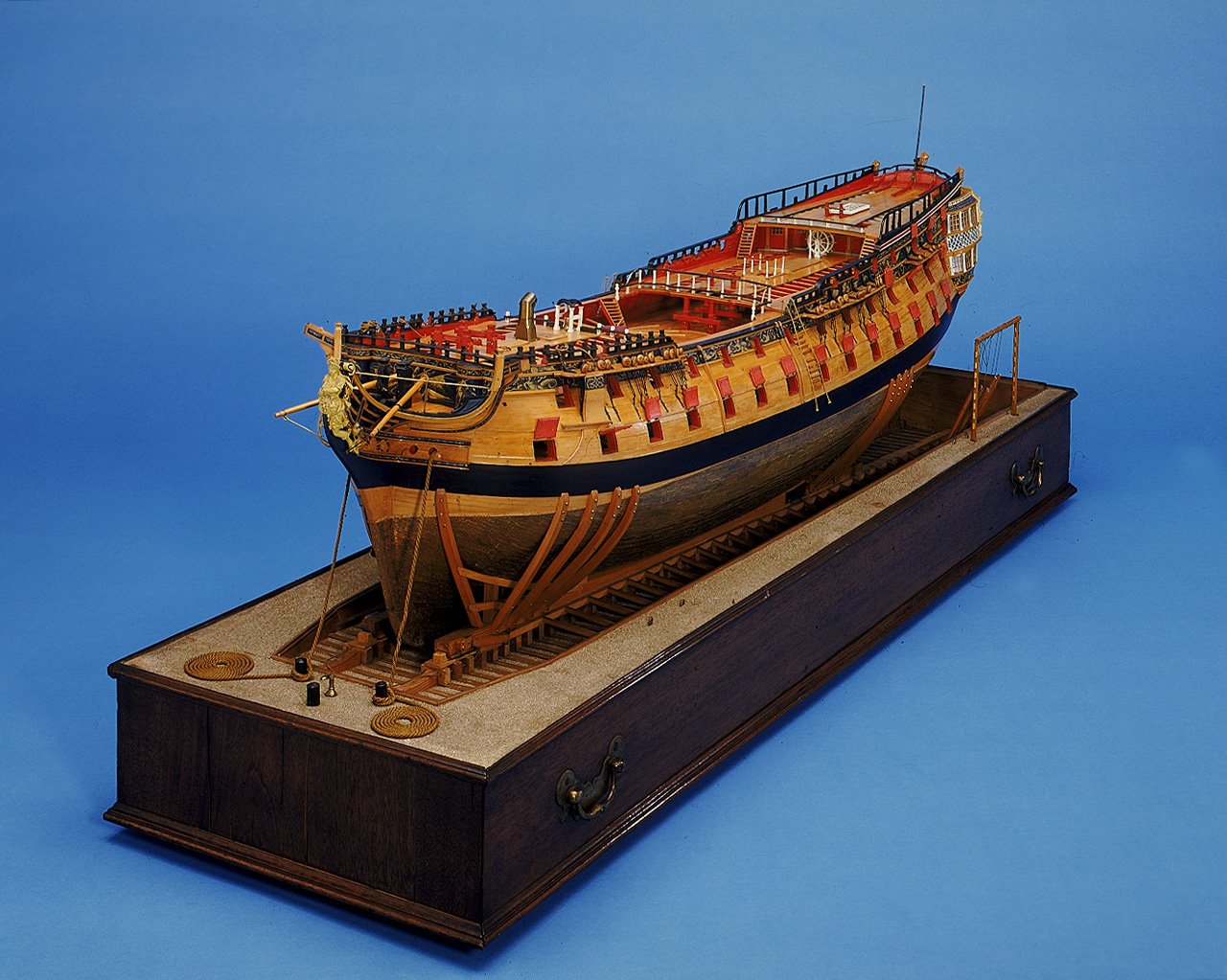
Hi Yves First and foremost, thanks for sharing your lovely build! To what beam are you referring? The upper deck is not shown in the first photo you added in post #362 so a bit confusing. I searched the National Gallery of Art but cannot find any photos of this model. There are a number of photos of a contemporary model of Bellona at The Royal Museum Greenwich that I found. (Maybe you can ID the beam you mention on the photo below from RMG as part of the upper deck in the waist can be seen in this photo) Prior to skid beams being introduced about five years after Bellona was launched, spare spars were laid from the fore edge of the quarter deck to the aft edge of the forecastle and the boats sat on top of these which would probably be appropriate at time of her launch. I would guess the gangways and skid beams were added at some point later on so could be appropriate on the model depending on the year. I may be completely wrong but pretty sure the Bellona did not carry any dinghies. At her time of launching in 1760 third rates carried five boats, a 32 foot long boat and 2 pinnaces and 2 cutters. By about 1780 she would have probably had a 32 foot launch in place of the long boat, as well as a 32 foot and a 28 foot pinnace, and two 25 foot cutters. (W.E. May The Boats of Men of War) Allan
-
Jim Rather than base a decision on advertising, there are hundreds of build logs of dozens of vessels here at MSW. Some kits get five stars, some don't. Spend a few days or weeks studying the many choices available. Look at the wide price ranges and when it comes to quality remember the old adage you get what you pay for. Allan
-
I agree it looks nice on the carriage. Unless having room for building a bulkhead and stanchions on which to mount a swivel gun the carriage is an alternative way to go. Allan
-
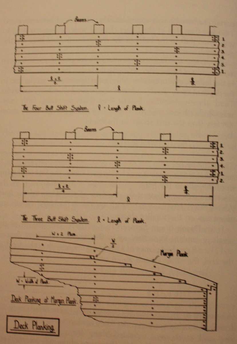
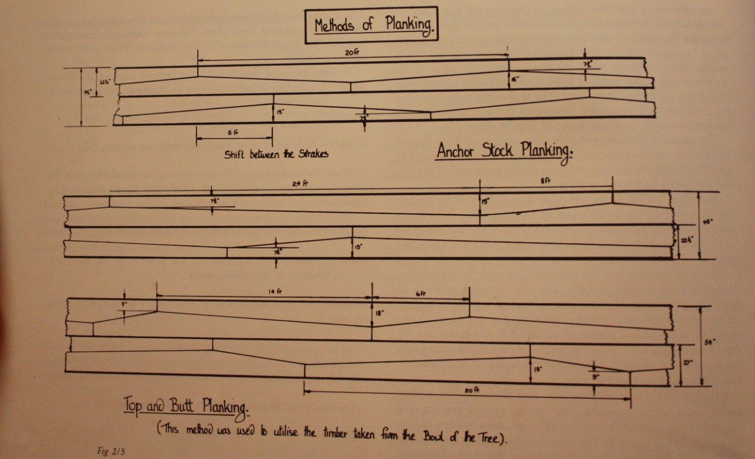
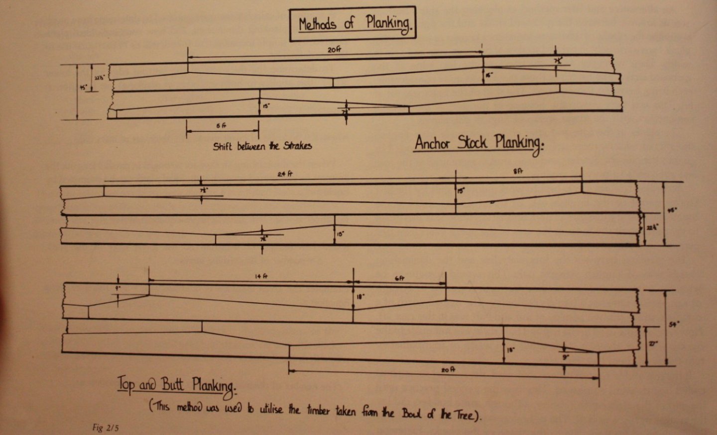
Good choice at this scale. At 1:85 any caulking is really not necessary and more often than not, it is out of scale and obtrusive looking. Still, your choice is a good one. Black tissue paper glued to the edges also does a very nice job of it as it is thin enough to be to scale and is much cleaner looking than pencil. You can find this on-line and at most craft stores. One package will last for many many years. Your planking looks very neatly done. You mentioned lengths. The lengths you chose are hard to tell in the photos. The lengths of deck planks near the center line of course varied a lot with the deck furniture and openings, but the longest "straight"pieces would be in the neighborhood of 3 1/2"- 4" at your scale. It is too late now, but they were normally laid in a three or four butt shift. (see first drawing below) It appears in the photos that you used a two butt shift pattern. I assume this is a kit error, but something to keep in mind for future builds. Regardless of kit or scratch, maybe consider getting a copy of Goodwin's The Construction and Fitting of the English Man of War or other book that covers an array of items. Much/most will apply to ships of other nationalities. There are dozens of other books as well, but this one covers a lot. An example is the deck planking of decks carrying cannon. The four or so outboard most strakes were often anchor stock or top and butt pattern for the added strength on decks that had cannon rather than straight pieces. See second drawing below. Both drawings below are from Goodwin's book. The first is on page 58 and the second is on page 52. Is there a reason you are not using PVA glue? I don't think there are many fans of contact glue in ship modeling, but may be wrong on this. Allan

-
Occre Diana (Spanish frigate 1792), low quarter gallery windows?
allanyed replied to Esap's topic in Wood ship model kits
That is quite a compliment, but alas, I am no expert compared to some. There are a number of written sources of terms and meanings mentioned in other logs and forums here at MSW. I will be honored to follow your build and help where I can and I very much admire you for wanting to learn. Allan -
Looks a lot like the drawing of the 1/2 pounder swivel gun (3 feet long ) from Fort Ticonderoga on page 59 of volume I of The History of English Sea Ordnance by Adrian Caruana. Using the photo as a basis, I estimated the bore diameter at about 1.5" which is close to the Caruana drawing for the 1/2 pounder. As the carriage is modern, MAYBE there was none to begin with and it was on a swivel as Caruana describes for his example. Were 1/2 pounders ever carriage mounted? Allan