allanyed
-
Posts
8,149 -
Joined
-
Last visited
Content Type
Profiles
Forums
Gallery
Events
Everything posted by allanyed
-
 Hi Yves. I am curious to learn how you arrived at this figure. I tried some calculations using scantlings from both Steel and the Shipbuilder's Repository, for a 74, Both put the sided dimension of the stem at the head at 24". Assuming the knee of the head is about the same or slightly smaller where it fays to the stem and then tapers as it moves forward to about half the thickness as was normal practice, it would be about 12". At 1:48 --- 12/48 X25.4 = 6.34mm I cannot find any other way of calculating this but would love to know of any. Thanks in advance for your help on this. Allan
 -
Hi Grant Blocks and their construction varied a lot so there is no set answer to your question without more information including, but not necessarily limited to, the nationality, ship, and year of the model you are building. Allan
-
That sounds like a great idea to try. I have used Permatex marker pens with success as well as I can cut the applicator tip to 2" scale width but can see how this can also be done with a soft coloring pencil. A bit a difficulty in this part of this step is finding a pencil or pen that is a color that is appropriate for the sail color. Either way, it looks so much better than out of scale cloth sails and stitching lines. Allan
-
How to Seize a Block to a Sail Peak
allanyed replied to Yorky1's topic in Masting, rigging and sails
Great question Yorky Chapelle's American Schooners gives some details on the halyards but for the clew line, the sketches are as clear as yours. It does mention on one sketch that the block for the clew is a single and made fast to the head of the sail. No mention of how it is made fast is given. Allan -
I thought this would be an interesting material to try....... then I saw the price for one piece 2"X6"X 12" is $161. Ouch. Allan
-
Welcome to MSW JC

-
Welcome to MSW Wonko!!! Please post an intro with a little about yourself in the new member forum here at MSW. Your machining work and carriage assembly is extremely neat and your designs for each are interesting. Allan
-
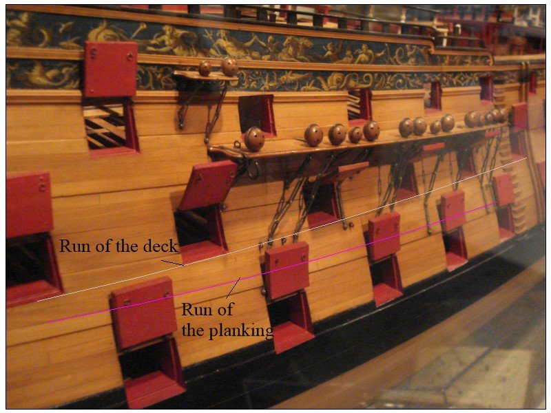
No worries Cisco. Looking at many contemporary models at Preble Hall and RMG, I could not find one where the planking is parallel to the deck line. This brings up an interesting point..... why are they different? I assume it has to do with structural strength but I cannot wrap my head around this. You are so lucky to only be about an hour or so from Preble Hall. I would probably do a lot less modeling due to the time I would be spending over there if I was that close! Regarding Chuck's videos, Ihis methods to work very well but I still like to soak the wood for the heaviest bends and I have stopped using an iron and gone to an industrial hot air gun that was about $20, delivered. I find it much easier to use than the iron but to each his own. Allan
-
Your work is VERY neat and clean, kudos!! For future projects, keep in mind that the gun ports are rectangular with corners that are pretty much square midships, but they are trapezoidal fore and aft. The top and bottom do not follow the line of the planking but rather the line of the deck which was different. Below is a contemporary model at Preble Hall that shows what I mean better than in words. Have you seen the planking videos on YouTube by Chuck Passaro? Allan
-
Cutty Sark Photos - Free!
allanyed replied to Kevin-the-lubber's topic in Masting, rigging and sails
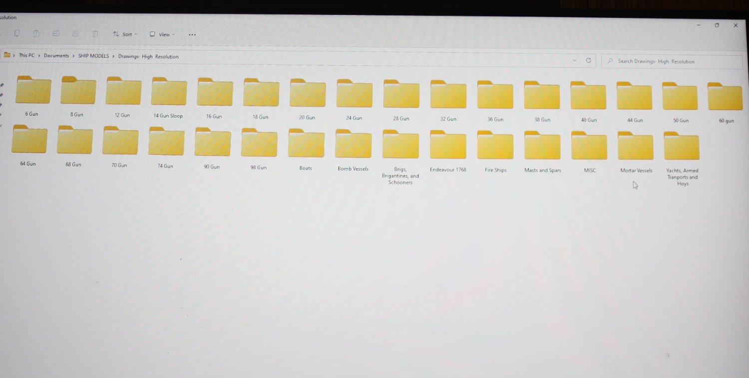
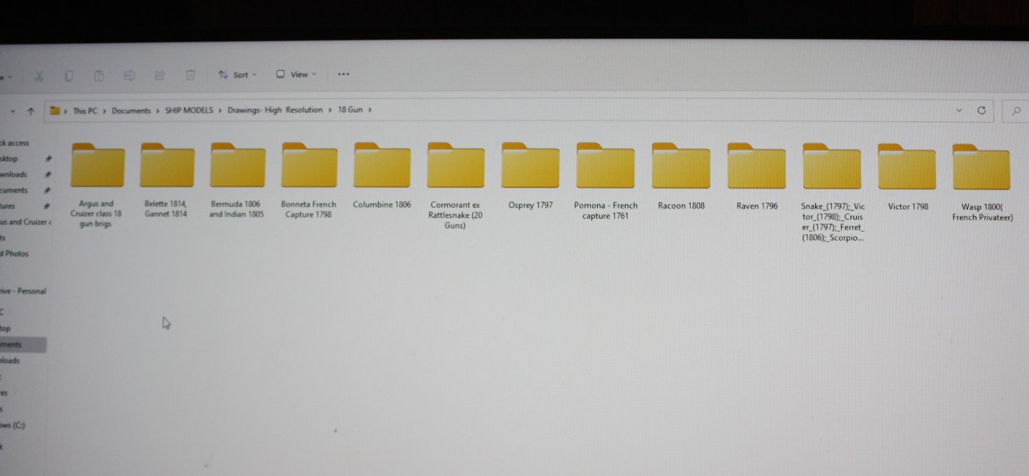
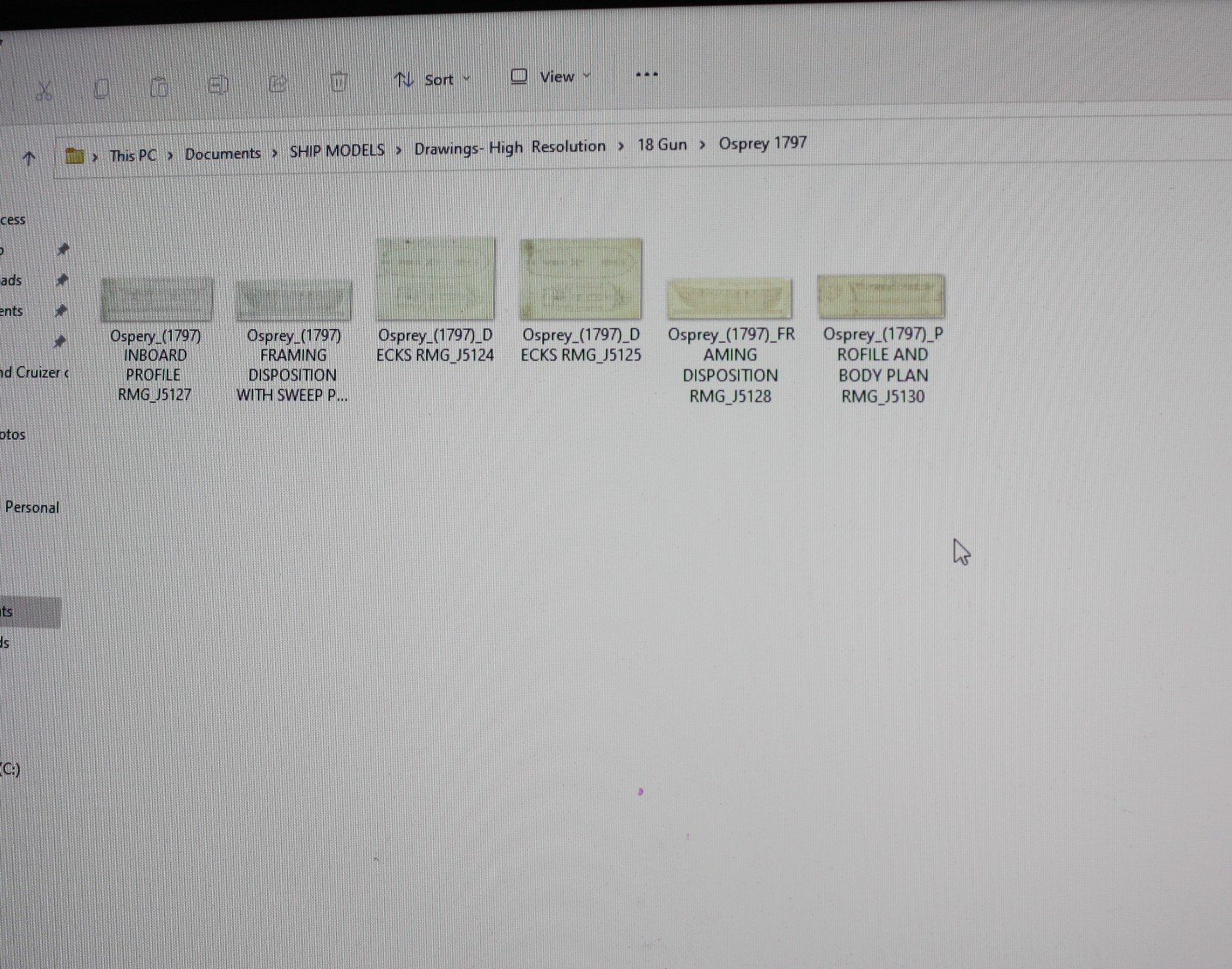
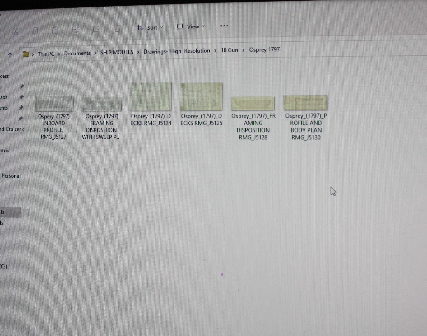
What is the limitation? I have saved 800 high resolution plans from the Wiki Commons site. The original thought was to have them in the articles base or similar place here at MSW with access for all members and set up for it to be live, thus able to take on new high res plans and grow. Seems this is not going to happen due to other priorities which I totally understand but I really hate to see all these plans sitting in folders on my computer rather than easily accessible to the entire membership. Maybe a dropbox set up is an alternative way to go. Most plans in my folders are between 20mb and 50mb each so we are looking at about 30gb maybe more. The plans are set up as follows and example shown below. First are the main category folders, second are the individual vessel/class folders, and last are the plans. Allan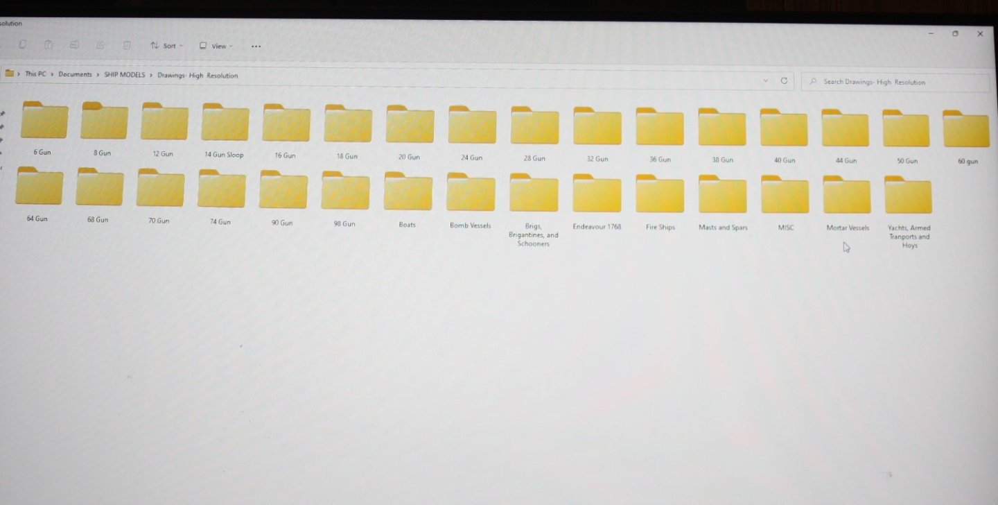

-
Slipping in from Massachusetts and Minnesota
allanyed replied to Janelle's topic in New member Introductions
Welcome to the fray!! Hope to see pics of your boats!!! Allan -
Cruizer-class Brig-Sloops of the Royal Navy
allanyed replied to molasses's topic in Nautical/Naval History
Andrew The post from nearly 9 years ago may not be valid. Keep in mind that the RMG has changed things and many files (plans, photos, documents) can no longer be easily found, if at all. Allan -
Bravo Chuck!! Phil Rizzuto's catch phrase says it all. Allan
-
Cruizer-class Brig-Sloops of the Royal Navy
allanyed replied to molasses's topic in Nautical/Naval History
Guy, Yes, the four of the Columbine 1806 are great! There are also those of the Argus 1813, Belette 1814, and probably some others, As there were 52 ships in her class and all being built in private yards, there may be a number of contracts available which will give you scantlings and more information. If the contracts are of interest contact RMG and the National Archives in Kew to see if they have any available for any ships of the Cruizer class. You may have to actually list the names of each ship in order to get info. The NA site is difficult to navigate for me, but you may have better luck. The RMG site is awful since they reformatted some years back, but they have been great in responding to emails if you can find a contact. I had a few names there but I am not so sure they are there any more, but you can always start with "plans and photos at rmg. co. uk" Allan -
Cruizer-class Brig-Sloops of the Royal Navy
allanyed replied to molasses's topic in Nautical/Naval History
Hi Guy, Which drawings do you have? I found five high resolution plans of Cruizer Class vessels on the Wiki Commons site as well as a low res planking expansion on the RMG site. Looking forward to your build!! Allan -
I am not a kit builder (so far) but I can see this as a beautiful project if/when the time comes that I am relegated to a small living space with a few hand tools and sandpaper to make at least a little bit of sawdust. Allan
-
I use the booklet as well with a variation or two. First I use tape to hold the span to the frame. Also, make sure to use the plug when wetting for the first shrink and again when painting. Do remove once wetted or when the paint is applied so it does not stick. I like to do two coats of diluted tubed artist acrylic. Allan'
-
Tthe blocks sizes can be determined from the tackle circumferences. For example, the circumference for the tackle for a 32 pounder, based on the mid 18th century Naval Regulations was 3". For the smaller guns they were 2" to 2.5" circumference. The lengths varied slightly and are also given. For the 32 pounders the tackles were 60 feet long. For 18 pounders as a comparison they were 54 feet long. Using Lees formula for calculating the lengths of the blocks on page 164 of The Masting and Rigging of English Ships of War, the block sizes would be as follows. For 3" circumference rope for 32 pounders 3/3.14= .96 0.96X1.1X1.0625 =~9" at your scale .09"X25.4 = 2.3mm long For the 2.5" circumference rope for 28 pounders 2.5/3.14= .8" 0.8"X1.1X1.0625X8 = ~7.5" /100 = .075X25.4 = 2mm For single blocks for 2" circumference rope for the 12 pounders the blocks would be 1.5mm long at your scale. While the blocks would vary in size for the size of the gun, keep in mind that with the exception of the 32 pounders, for the running out tackles there would be only single blocks used. For the 32 pounders there would be one single and one double block for each tackle. Caruana goes into this on page 386 in volume II of The History of English Sea Ordnance. Same holds true for the training tackle. We often see incorrect blocks on models where one or two doubles are mistakenly used on guns smaller than 32 pounders. Allan
-
Royal navy - stern colours?
allanyed replied to Vane's topic in Painting, finishing and weathering products and techniques
Jason, While they do not usually make mention of paint, do you have a copy of the Jason contract? I have found that if you can find a contract for the ship you are modeling, the scantlings and such are extremely helpful overall. There is a 14 page contract for a number of Artois class ships, including Jason 1794 at RMG. https://www.rmg.co.uk/collections/objects/rmgc-object-459306. As it is a relatively modern ship, the contract was probably printed with typeset so easy to read compared to the hand written contracts from earlier years. Allan -
What is a harbored hardboard plank? Are you sure you do not mean the garboard as in your other post? Thanks Allan
- 1 reply
-
- 1
-

-
Hi Mr. Design, What vessel are you building? The planking tutorial in the article data base by David Antscherl is worth some hours of study and use when doing your build. https://thenrg.org/resources/Documents/articles/APrimerOnPlanking.pdf Of particular importance is the following comment in that article. The point of this photo is to show the forward end of the first strake, the garboard strake. It should not be carried high up the bow rabbet: a common beginners’ error. If the garboard is carried up too high, the remainder of the hooding ends of the planks (the ends that fit into the rabbet) will be crowded together and be too narrow, or too many drop strakes will be required forward to compensate. There are details in a number of books and you can also study contemporary planking expansion drawings found on the RMG Collections site. https://www.rmg.co.uk/collections/objects/search/planking expansion plan If you use these, notice that there are both inboards and outboard planking expansions which must obviously be done differently. Allan
-
Royal navy - stern colours?
allanyed replied to Vane's topic in Painting, finishing and weathering products and techniques
You are absolutely correct Mark. I went to the site and it does indeed give credit to Mr. LIghtley. Thanks for the catch!! Allan -
shaping masts, yards and bowsprits
allanyed replied to Charlie pal's topic in Masting, rigging and sails
Further to Bob's comments, if you start with round stock (dowels) you can anchor a hand drill and use it as a mini lather, but are probably limited in the type of wood. Obviously oak is not a great choice as it is so grainy, but some of the other common species used for dowels might work for you. In addition, for British ships there are quite a few scaled and/or dimensioned contemporary drawings of masts and spars on the RMG site and I think a few on the Wiki Commons site. David Lees gives dimensions of all spars and masts covering 1625 to 1820 using ratios as an appendix in his book The Masting and Rigging of English Ships of War. There are also spread sheets available here at MSW in the articles data base by Dan Vadas, (https://thenrg.org/resource/articles) The Vadas sheets use the same ratios as Lees except for the period 1670-1710 where unfortunately he made up his own formulas rather than use those provided by Lees. Allan -
Royal navy - stern colours?
allanyed replied to Vane's topic in Painting, finishing and weathering products and techniques
From Naval Miscellany by Angus Konstam, 2010. (I have no idea what his sources are): The Nelson Chequer was a color scheme adopted by vessels of the Royal Navy, modelled on that used by Nelson in battle. It consisted of bands of black and yellow paint along the sides of the hull, broken up by black ports. In the 18th and 19th centuries, vessels of all nations were painted in a variety of colors. Captains were allowed great latitude in the way they painted their vessels, as it aided identification in battle. Periodically the Royal Navy sought a uniform color scheme; In 1715, an Admiralty order decreed the use of yellow and black, and a uniform color within. However, this was generally ignored. Again in 1780 the Admiralty then issued a further order allowing captains to paint in yellow or black. Below is the stern of a contemporary 50 gun model at RMG circa1715. https://www.rmg.co.uk/collections/objects/rmgc-object-66365 Someone apparently did not get the memo.🤪 Allan -
Royal navy - stern colours?
allanyed replied to Vane's topic in Painting, finishing and weathering products and techniques
In addition to colors keep in mind that the names were not normally painted on the stern of RN ships prior to the 1771 order of the Admiralty. They were allowed until the Admiralty rescinded this in 1782 so it is only a ten or eleven year window where the names were commonly found. Were there exceptions, probably. This order from the Admiralty obviously changed again many years later, but I am not sure if was in the late 19th or 20th century. Common sense comes into play here. Flying false colors and such was supposedly used on occasion when coming on the enemy. Having your ship's name on the stern would pretty much negate the idea of flying a false flag. I don't know which Granado you are building as there were several built by the RN over time, but look at photos of contemporary models in your time frame on the RMG collections site for some ideas. Their model of the Granado 1742 has the lower counter painted black and no name is on the stern.