

DocRob
-
Posts
1,149 -
Joined
-
Last visited
Content Type
Profiles
Forums
Gallery
Events
Posts posted by DocRob
-
-
Absolutely fantastic result Dan. I love, how colors and decals blend and the restrained weathering. Getting the spinners right must have been a chore.
Cheers Rob -
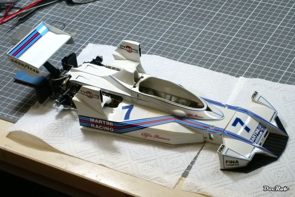
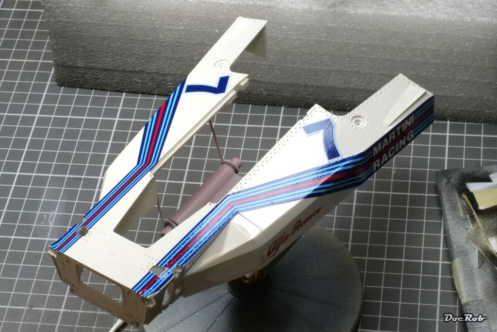
There are few steps more rewarding in modeling than to finish a car body to a high shine surface. All the work going into took a while, but I love doing the polishing as a last step. I used Tamiya´s polishing compounds starting with coarse, then fine, followed by finish. I didn´t apply wax now, because there are still many parts to add to the body, so this will be kept to the finish.
The coarse polishing is by far the most important and also time consuming one to my eye, as you remove all the tiny imperfections, check against the light and continue until all looks good, always taking care not to polish through the clear coat.
I couldn´t resist a little workbench mock up.


Cheers Rob -
9 hours ago, kgstakes said:
From the looks of the parts it’s going to be a lot of time at the spray booth as well.
Looking forward to the progress as you build this one!!
Airbrushing is already done and didn´t take up much time. There are three sessions, first primer, than three coats of body paint and finally three coats of clear. The prep and polishing time exceeds the spraying time by far.
Cheers Rob -
Clear coating went very well. I used Zero Paints lacquer clear, which did a fantastic job on my Cobra Coupe. My approach is similar to the application of the base coat and it works for me.
First, I spray a thin un-thinned layer, which dries very quickly with the help of the airbrush blow, to hinder the aggressive lacquers to attack the decals.
The second layer after about 15 minutes consists of about 25%-30% leveling thinner and is applied "wet"
After again 15 minutes of drying and leveling time, I applied the third layer, this time with 50%-60% of levelling thinner, this time very "wet".
The brief drying time leads to later layers "melting into the layers applied before and give a better surface. I may could push my luck with the application of pure leveling thinner as a fourth coat, but I fear running paint.
The result looks far better to the real eye than on the pictures, but I learnt through other builds, that´s always the case with high shine finishes.
Anyway, today or tomorrow I will slightly sand and polish the surfaces.

Cheers Rob -
19 hours ago, gsdpic said:
I had to react with the open-mouthed "wow" emoji because that is exactly what I did in real life when I scrolled down and saw the picture. The body and decals look flawless. Thanks for the warning about the MFH decals.
Thank you Gary, in fact the decals are perfect to work with, beside that cover foil thing. I guess, it is meant to be a protective layer, but can easily be overseen. The good about the decals is, they are robust, perfectly printed with vivid color, high opacity and perfect size. They apply very good with lukewarm soap water alone. For the rivet holes on the body, I applied a bit of Micro Sol, which made them easily settle into the holes contours.
The newer MFH kits have Cartograph decals without that foil, but the Cobra Coupe and the BT45 had them both.
Cheers Rob- rcweir, Canute, Old Collingwood and 3 others
-
 6
6
-
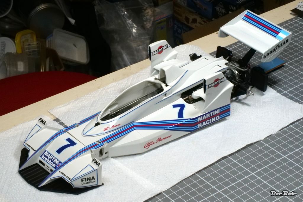
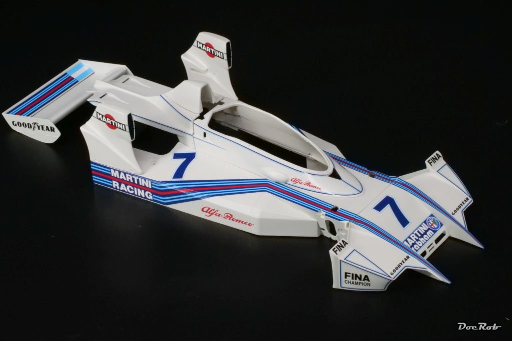
Finally some serious progress. I finished decaling the body parts, after a long period of prep work.
My usual method is read the manual, understand the manual, drill all needed holes, fill and sand where needed, sand all resin surfaces carefully with 4000 grit, clean all the parts first in soap water (helps to reduce the static, these resin parts possess, which makes them like dust magnets) and wipe it with alcohol. Next was Mr. Color 1500 white primer, which sprayed fantastic like always. After a day of drying time, I checked the surfaces again and then applied the body color, in this case Number Five´s Brabham BT44 white, which is a tiny bit off white.
I sprayed the first layer un thinned, let it cure for some minutes, followed with a mix of about 25 % leveling thinner and paint and let dry for some more minutes. The last layer was applied with about 50 % of thinner and the relatively short drying times helped, that the later layers "soaked" into the base layer.
There was extremely minimal orange peel, which completely vanished after half an hour of drying.
I have to say, these Number Five colors are fantastic to work with an give the best possible surface results. I used them for the Cobra Coupe as well.
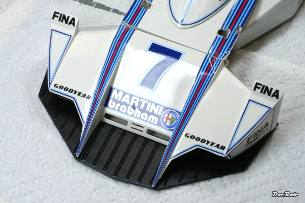
I feared decaling a bit with the thin pinstripes and huge decal bands slung around the body. I didn´t need to worry, the decals were fantastic to work with and were applied using warm soapy water only. One word of warning though, MFH decals are covered with a very thin very transparent plastic sheet which slightly adheres. Take care, you remove it before applying the decal, because it sticks to the foil much better than to the backing paper after soaking and you have to carefully peel the decal off the foil with a scalpel blade, which is really no fun. I only missed to remove the foil with two decals, but man, was I sweating.
Cheers Rob -
The preparation of the resin and metal parts for all body and the front suspension is quite time consuming, but the fit is overall very good. All body parts got cleaned up, surface sanded, washed in soap water, swiped with an alcohol soaked cotton rag and finally primed with Mr Surfacer 1500 whit primer, which laid down beautifully.
In the meanwhile, I glued together the polished cockpit tub and added some accessories. The battery and fire extinguisher will be hidden under the seat later.
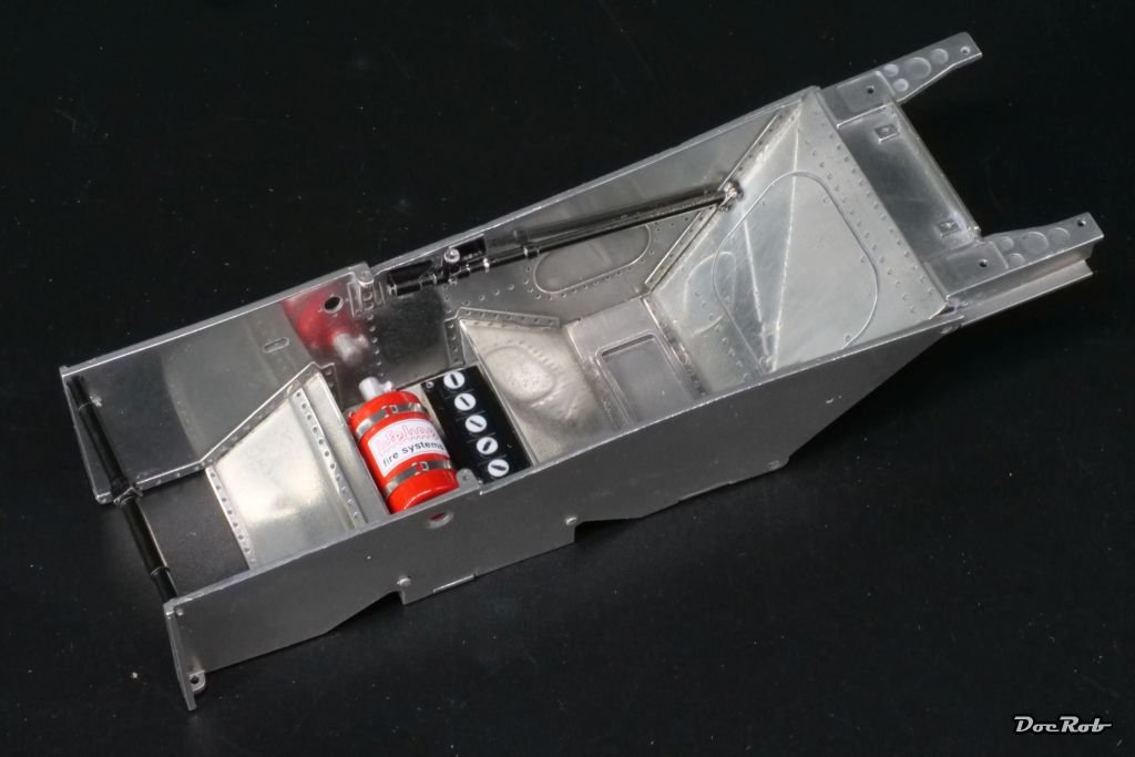
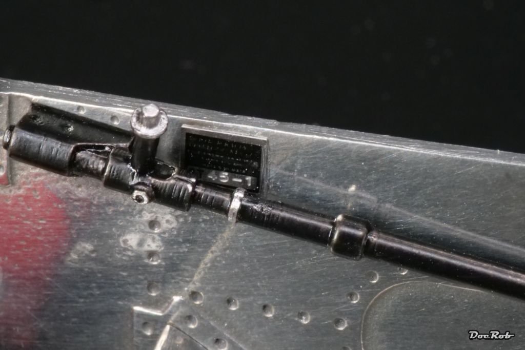
One beautiful detail is the number plate of the chassis. It has an etched part as a base, with the chassis number etched in. Onto that, you apply a transparent and black decal with the labeling, a bit hard to see on the pic.
Cheers Rob -
Very nice work and a joy to follow.
Cheers Rob -
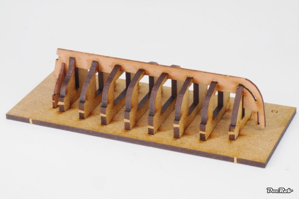
There is not too much to show at the moment, as I´m preparing all the resin parts and some of the metal parts for the next steps. Test fitting is time consuming, but helps to recognize, where everything fits and how.
During this test fitting period, I made a mock up workbench build up.
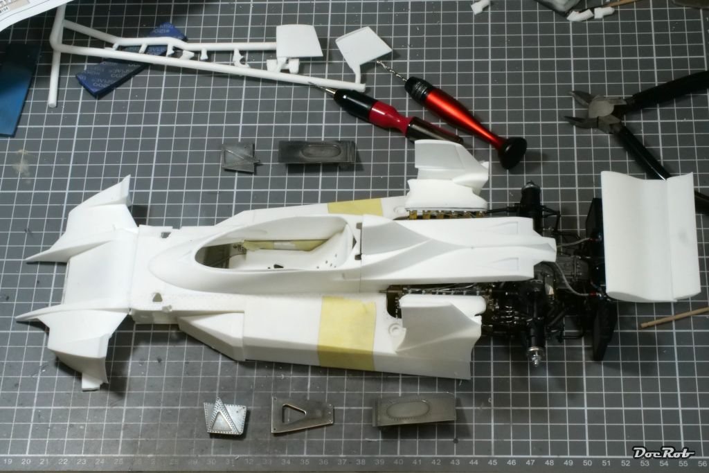
Cheers Rob -
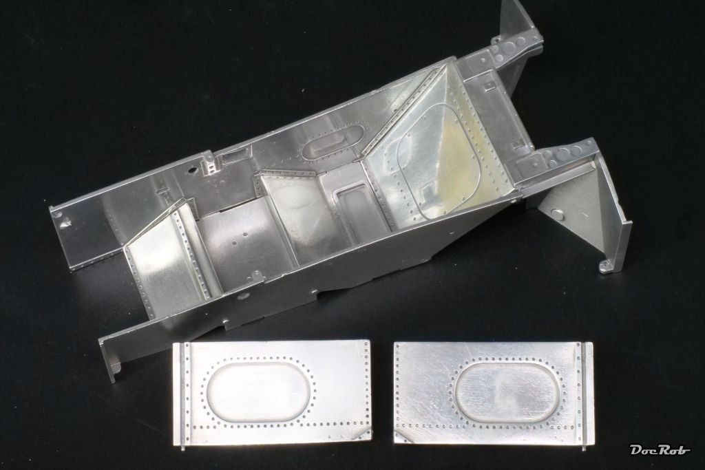
Yesterday was the day of mano negra, the black hand
 . Polishing white metal makes your fingers black with the metal residues, but despite the dirt, it is fun.
I used sanding sponges of 1200 to 6000 grit, to get rid off the cast imperfections, then it was about polishing with a cotton swab and Autosol metal polishing paste with works really well. I like the shiny look a lot and it could pass for polished aluminum to my eye.
Today, i test fitted for some hours, as now is the decisive step, where the tub has to fit into the body, along all the mating parts.
Cheers Rob -
18 hours ago, yvesvidal said:
Thank you Rob. You may not have the courage to do a wooden ship model, but I will not have the courage to put together an Hiro Factory model the way you do it for all these beautiful automobiles. I am glad that we can admire and appreciate each other master-pieces in different domains.
You are absolutely right Yves, it´s always a pleasure to see how fellow modelers skillful work on their models. It´s not only entertaining but I learned a lot through the build logs of others, even if the subjects are of a kind, I may never tackle myself. I once ventured into wooden ship modelling building Vanguard´s Duchess of Kingston in three month sans rigging and had immense fun doing it. When I ever finish the rigging, a task I´m really afraid of, I have the HMS Sphinx as my next wooden ship on line or maybe a heavy weathered Fifie fishing vessel from Amati.
I sometimes looked at the CAF kits, but decided, it´s far over my skill level, but who knows, maybe in a decade or two...
Cheers Rob- Paul Le Wol and yvesvidal
-
2
-
Very fine figure painting skills you show here Alan. You make it look like a much bigger figure and I always have to remember its only 75 mm.
Cheers Rob- Jack12477, Old Collingwood, Canute and 1 other
-
4
-
What a masterpiece, Yves. It´s a joy to follow your great build and log, even, when I never will have the courage to build something similar.
Cheers Rob- yvesvidal and Paul Le Wol
-
1
-
 1
1
-
2 hours ago, yvesvidal said:
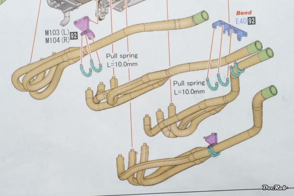
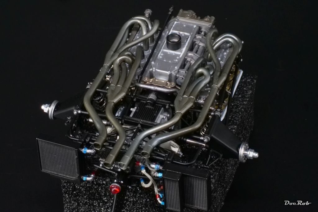
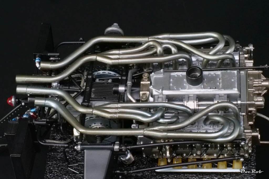
Just amazing. These exhaust pipes seem to come out of an Alien Movie.
You are right Yves, the exhausts look like Alien entrails and they are slippery as eels, when test fitting. It must be hard to design the exhausts with the idea of getting all twelve tubes at the same length.
Cheers Rob
-
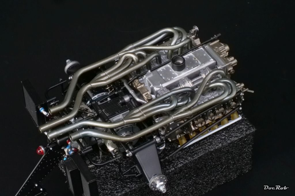
After a little pause, caused by one of my birthday presents, a week trip to the beautiful town of Valencia, I continue with the Brabham. I left the kit with the prep work for the exhausts just started and dreaded continuation, as F1 car exhausts can be a nightmare to build up. I cleaned all the parts and grouped them, followed by drilling all needed connecting holes. I then test fit the manifolds and glued the parts together with CA.
MFH claims silver for the exhausts, but what I saw on pictures led me to think of brownish stainless steel. I used metal etch primer, followed by AK´s exhaust manifold and accentuated it with metallic blue for heat staining.
While assembling, I tried to install the always dreaded coil springs before ore after inserting the exhaust, but failed. If I have a good idea, how to install these, I do it later or improvise somehow.
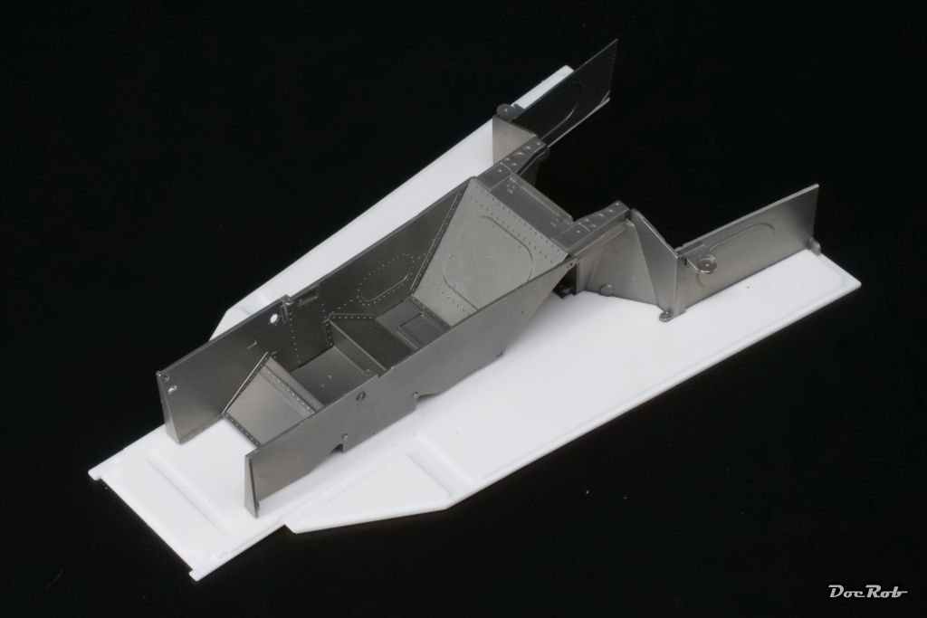
As a preview, I started to prepare the monocoque parts, which need to be finished in polished aluminum. I´m unsure, If I airbrush the aluminum or if I polish it, which will be difficult due to the shape of the parts.
Cheers Rob -
The tyres and rims look very promising Craig, especially for a first try. With the body and doors, I´m not so sure. lots of visible fragments, which will be nightmare to remove without losing detail. At least, it looks so in your pics.
It seems you can do about everything with a 3D printer right now, but I vaguely followed some discussions about resin types, software glitches, etc. and decided for myself, that I will not plunge into it. I have too many time consuming hobbies to add another, but as a hobby 3D animation producer and CAD user many years ago, I´m not sure, if I can resist forever.
To see your good work doesn´t make it easier to let the dive into "new" technology pass.
Cheers Rob- CDW, Canute, thibaultron and 4 others
-
7
-
1 hour ago, CDW said:
Very nice progress. Are you following the MFH paint guide or using your own choices? Whichever, it looks very authentic.
Thank you Craig, I don´t follow the MFH paint recommendations to the letter, as I don´t have any Mr. Color paints. Generally, I found the paint instructions from MFH well researched, but I try to use photos for reference as well, wherever possible.
I have some go-to colors, like Tamiya LP-5 semi matte black and LP silver for detail painting of nuts and bolts. For metal colors, I use primarily Ak´s Extreme metallic paints, which are spraying very good and fine grained and are more durable than Alclads. For aluminum tones, where MFH claims silver, I use the appropriate paint from AK´s range.
For metal parts, I generally refer to pics and my knowledge about materials (I was a metal engineer in a former life), to get the tone right.
Cheers Rob- CDW, Ryland Craze, Jack12477 and 2 others
-
5
-
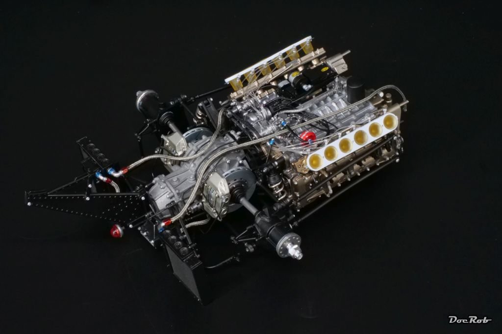
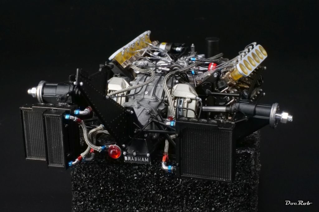
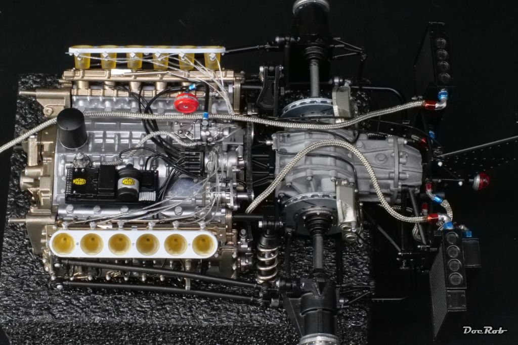
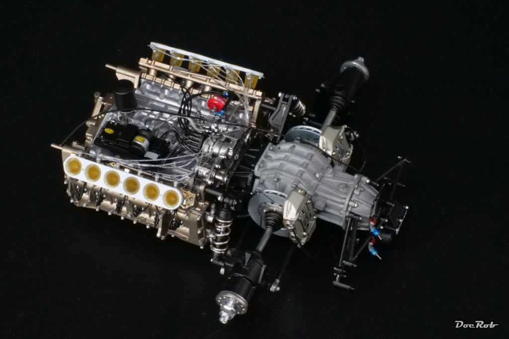
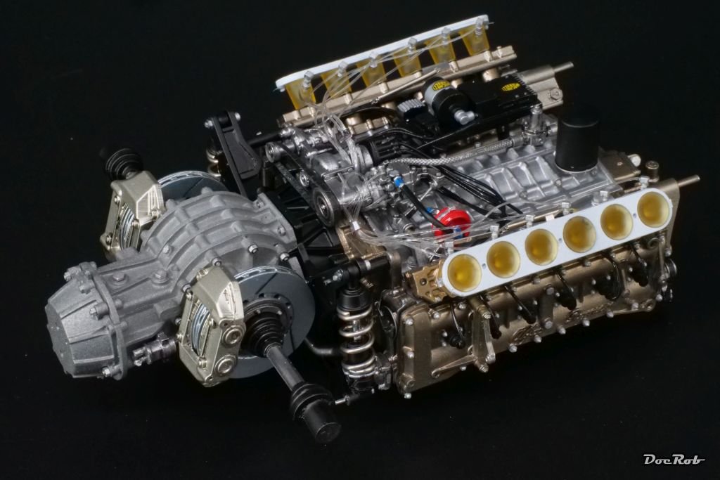
Chapter 9 of 20 in the manual is done and the rear section got finished sans the wing. Connecting the gearbox with the engine proved a little tricky due to numerous connection points, there is the suspension with adjustment bars, side rods and a shaft to connect all at the same time, trying to insert the screws for fixing everything. In the end it worked.
Another annoying part were the brake lines. The angled tube fittings provided by MFH were badly cast and I used resin ones from the spare box, but two of them broke and needed to be drilled out again.
I also substituted the white cast braided lines from MFH with braided textile hoses from Top Studio, which were far easier to work with. The cast ones need to be lengthened and bent, then drilled out with a 0,5 mm drill bit at the ends, to accept the fittings. Needless to say, that wiggling some of them in is nerve testing. The textile Top Studio stuff only needs to to be lengthened and then stuck on the 0,5 mm rods of the fittings with a drop of CA. Even my relatively liquid go to CA doesn´t soak and darken the braided hose.
Cheers Rob -
What a classic beauty, Craig. Your Ferrari came out perfect with it´s high shine finish and great detail all around.
Cheers Rob- CDW, Old Collingwood, Canute and 1 other
-
4
-
-
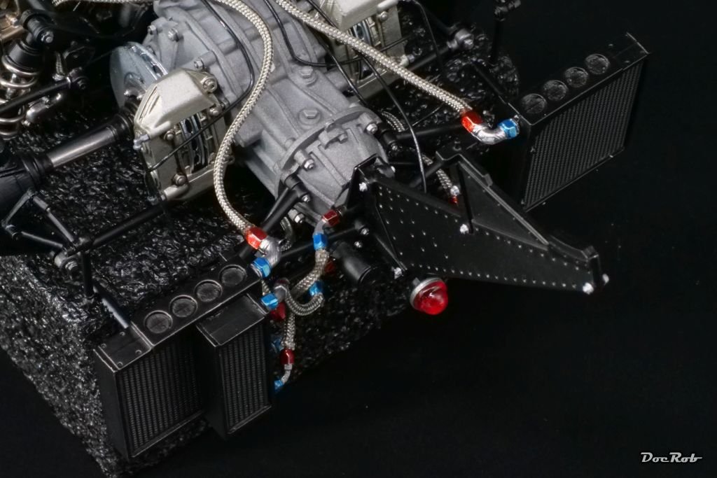
I finished the gearbox assembly step and started with the braking tubes. The fittings were badly casted by MFH, so I substituted them with resin ones. I stopped with the tubing and wiring for now, as I think, it´s easier to do it later, where it becomes more clear, which hose leads where.
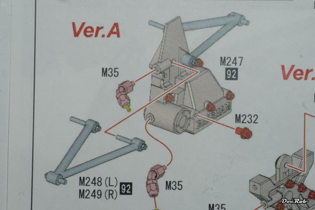
If there is anybody out there building the same "Press Version" of the BT45 be aware, there is a mistake in the manual, which can only be discovered, when analyzing later steps. Part 248 (9) doesn´t go into the shown hole, but in the one to the left. It took me a while to figure out, how the supports for the coolers (248 (9)) will properly sit. The shown hole accepts the rear wing support later.
Cheers Rob -
12 hours ago, yvesvidal said:
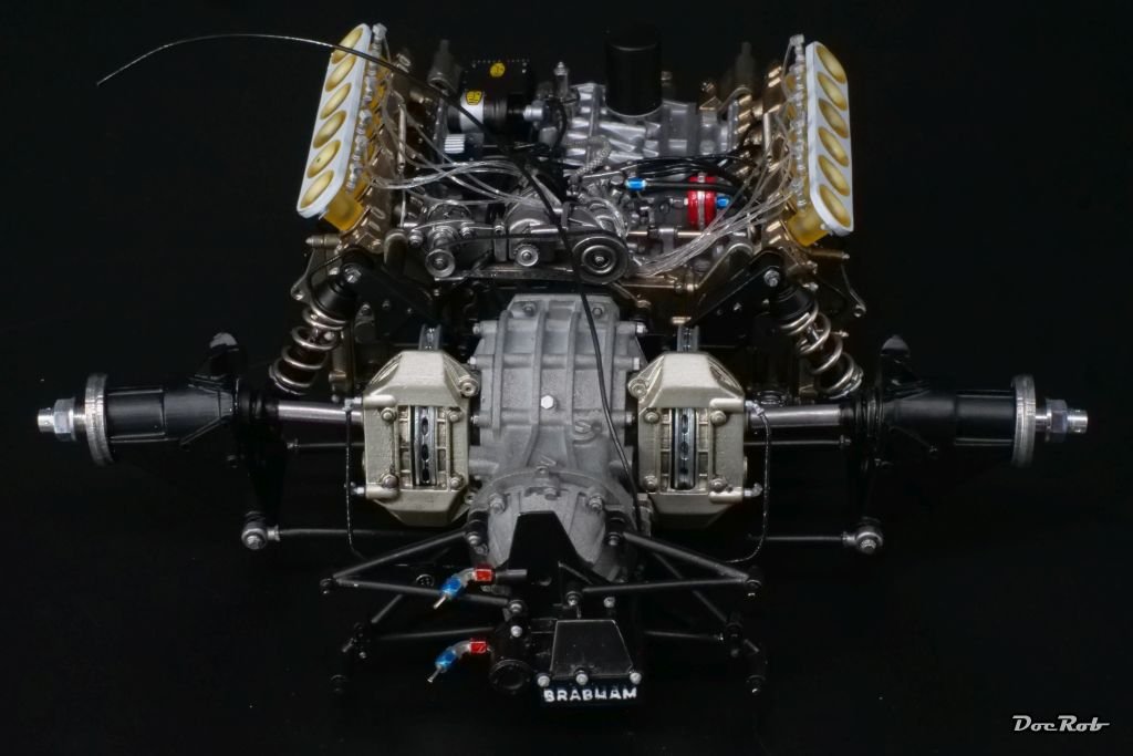
These brakes reminds me of the disc brakes used on the Citroen ID and DS and later on XM. Having the brakes next to the gearbox, reduced the UN-suspended weight and allowed for massive stopping power.
Indeed Yves, there are several advantages, but ease of maintenance and heat distribution were speaking against it. I love the DS, what an innovative beauty, there are so many modern ideas implemented, it would last for a decade with other manufacturers. I had to really laugh, when Mercedes announced the first steerable headlights around the century mark.
The DS is my favorite car and I would buy one, but the terrain, where I live and the possibility for proper maintenance is not given, unfortunately.
BTW: The Brabham BT45 was the first car, with carbon/carbon brakes used in an actual race. Mine has steel disks though.
Cheers Rob- yvesvidal, king derelict, CDW and 2 others
-
5
-
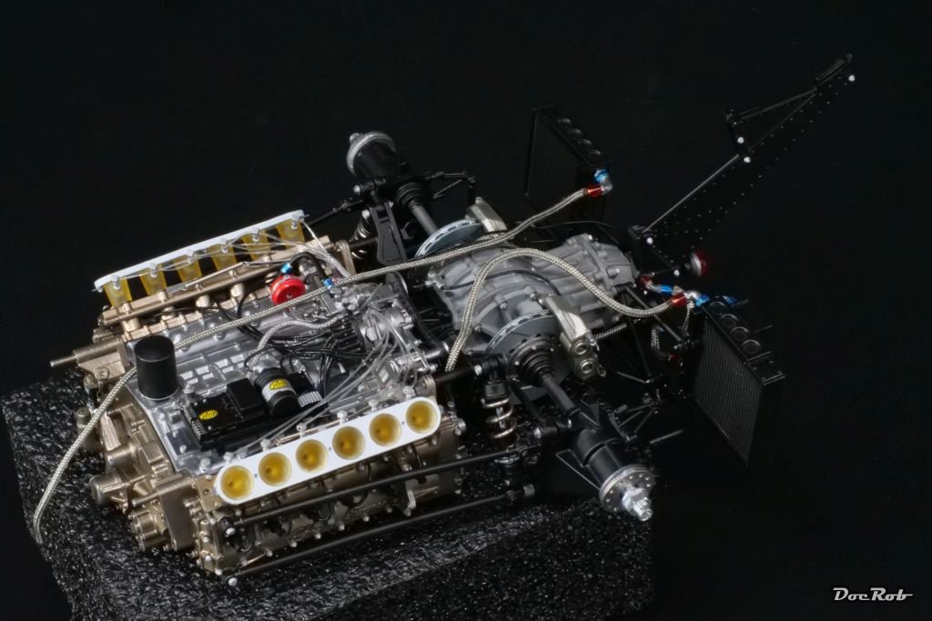
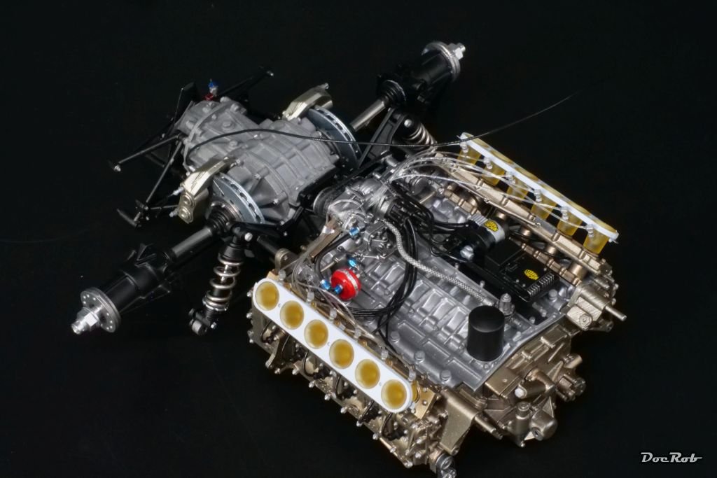
Next was the suspension, which is directly attached to the engine. The damper rods were painted with AK´s chrome marker and look really chromish, not like the to my experience really bad Molotow marker.
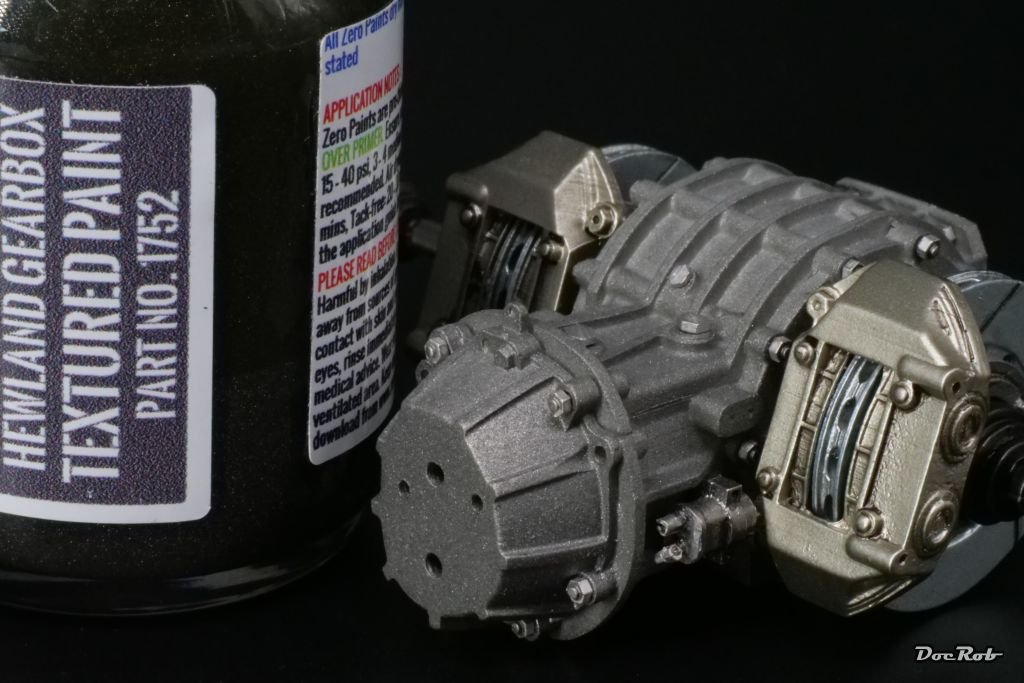
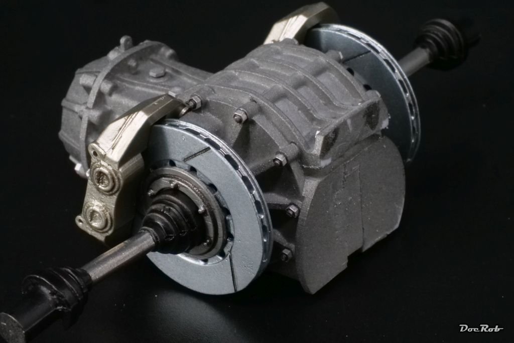
This was followed by prep work and drilling for the gearbox section, where a lot of bolts and screws are to be added. For painting the gearbox, I used Zero Paints Hewland Gearbox Texture paint for the first time, because it is a Hewland gearbox and have to say, I like the result, at least for a 1/12 kit.
I followed the recommendation of using a larger nozzle on my airbrush (0,4 mm) and raised the air pressure to almost 3 bar or 40 psi, to prevent clogging.
The brake disks were sprayed with Extreme Color stainless steel, therefore the slight bluish tint and the calipers were sprayed with duralumin.
Cheers Rob
-
Wow, what a fantastic looking Ferrari, Craig. The blood red paint job is gorgeous and the white trimming on the seats is the cherry on the cake, like Dan said. The USCP wheels are clearly better than the supplied ones.
BTW: I checked the wire spoke wheels with my Fujimi 1/24 Ferrari GTO and decided against the USVP wheels, because mine have aluminum rims and layered etched spokes, which look extremely fine.
Cheers Rob- Canute, Ryland Craze, Danstream and 3 others
-
6

'34 Ford Chopped Top Coupe by CDW - 3D Resin Printed - 1/25 Scale
in Non-ship/categorised builds
Posted
Looks absolutely supercool, Craig.
Cheers Rob