HOLIDAY DONATION DRIVE - SUPPORT MSW - DO YOUR PART TO KEEP THIS GREAT FORUM GOING! (Only 24 donations so far out of 49,000 members - C'mon guys!)
×


Javelin
-
Posts
624 -
Joined
-
Last visited
Content Type
Profiles
Forums
Gallery
Events
Everything posted by Javelin
-
 And shorter, as you can see on the above drawing, the side of the boat rests against the fender on the davit arm when inboard. The hanging point, tip of the davit arm, is in the middle (transversally) of the boat. You'll have to shorten the arm so that the tip is half of the boat width outboard of that fender. Hope my explanation makes sense...
- 300 replies
-
- 8
-

-

-
- lightship
- Feuerschiff Elbe 1
- (and 1 more)
-
Hi Keith, I actually fully agree with Kuparu on this one. Hadn't thought of that before, since echosounders are normally keel mounted on big ships, but there's no space for that on this one. The cap forward of it, is probably installed to deflect bubbles created by the bow wave, a common issue on echo sounders. On big ships, with larger drafts, there's no cap, but they are mounted more aft (relative to the bow) than on Cangarda.
-
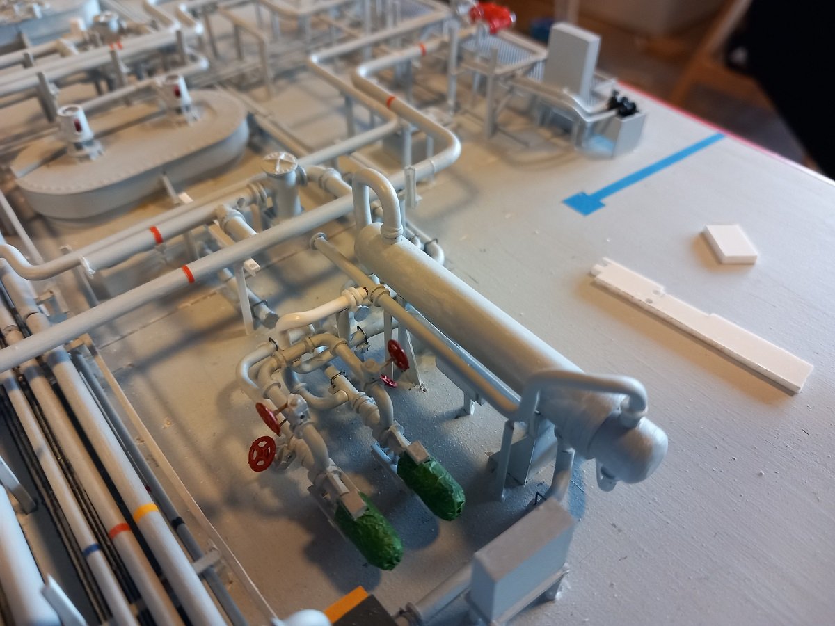
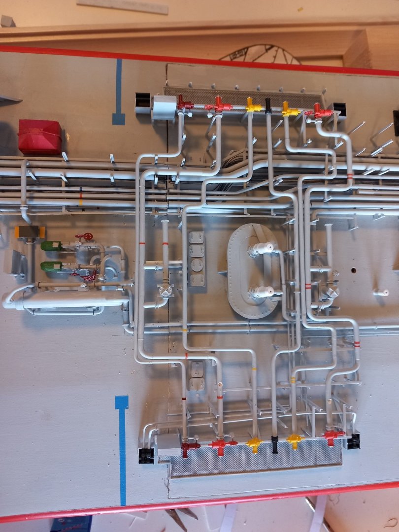
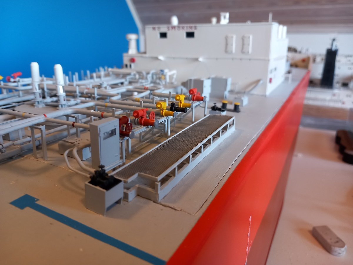
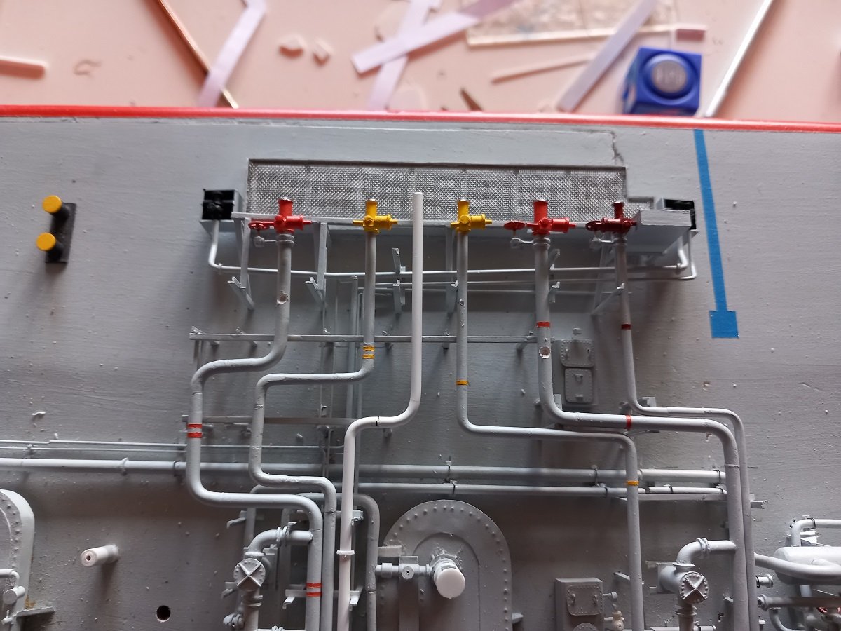
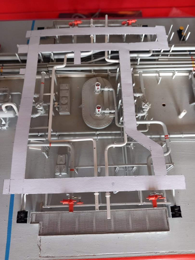
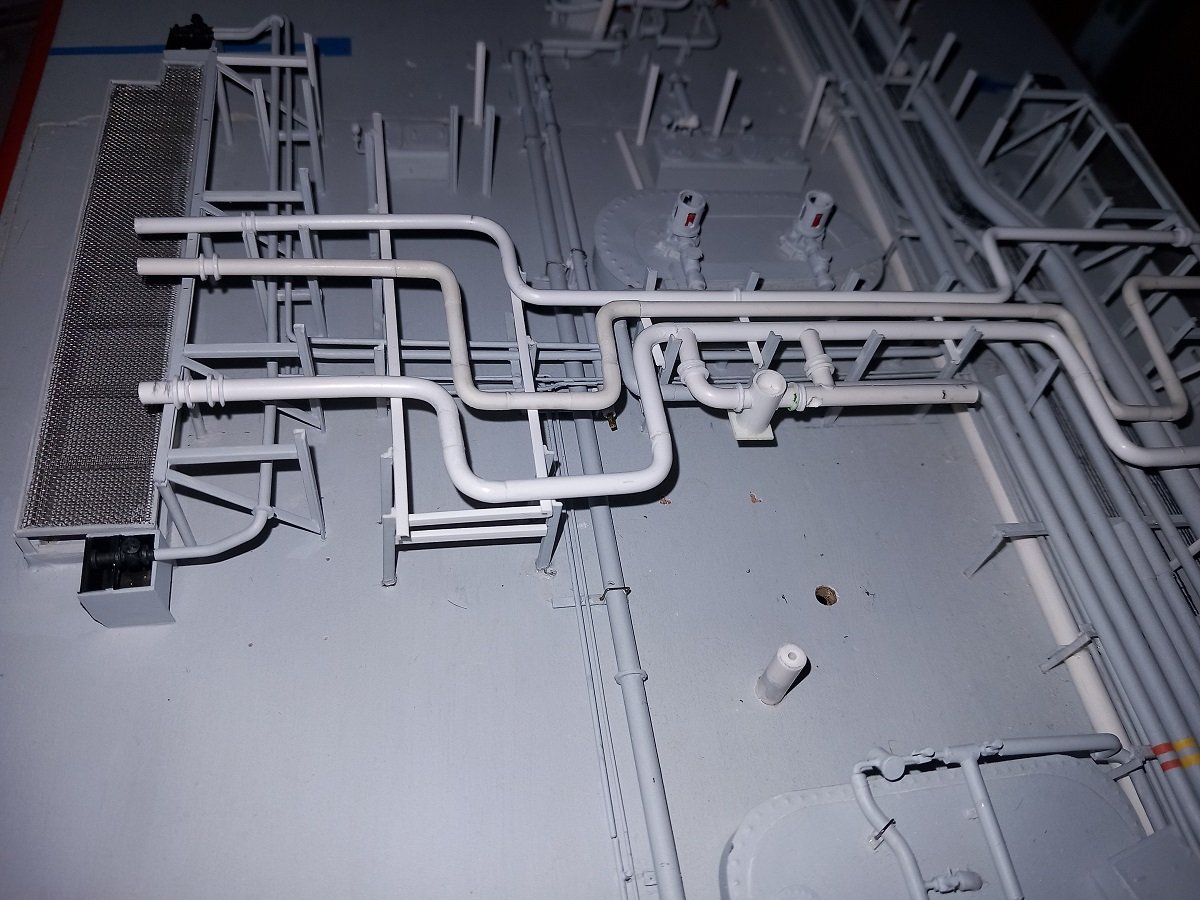
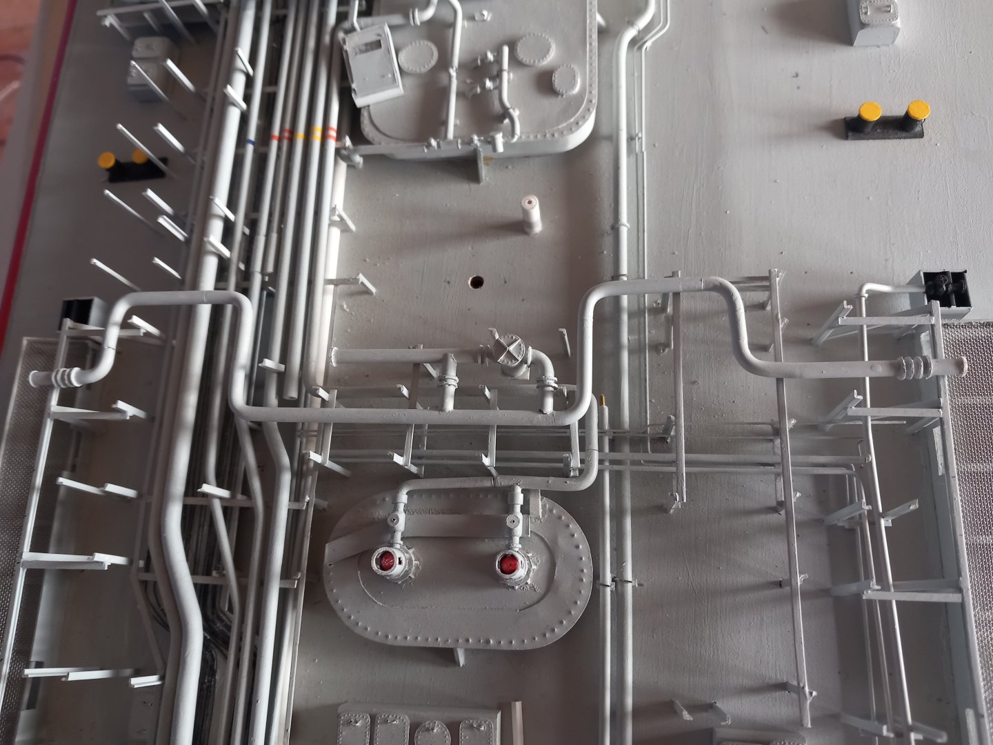
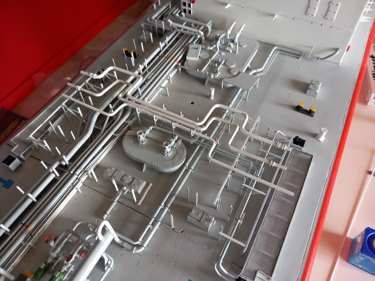
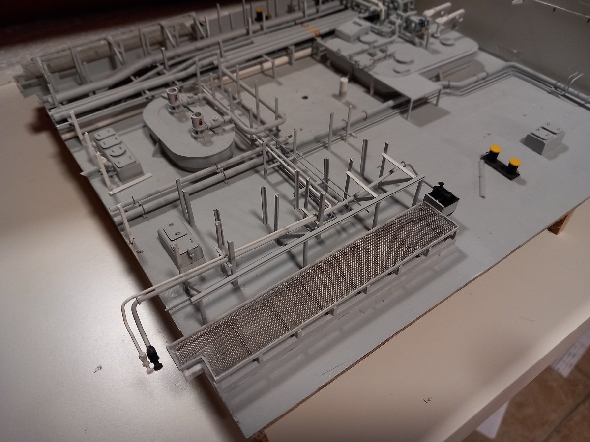
Time for another update as I'm finally finishing that manifold area, something I hadn't even thought possible apart from the very start of this model. I was waiting for yellow paint to arrive, so I continued with the dreaded last line on the booster-heater system. The line ran below the rest, then came up, turned over to finally arrive at the discharge. Quite a puzzle of mounting, fitting, adjusting etc. Then the yellow paint arrived, so I could finish the vapour lines on the manifold, fix them in place and start working on that last crucial Inert Gas line. Below was my initially bent pipe, bent around 10 years ago without really having anything else apart from the plan. You can see what I mean with having the distances between the lines symmetrical and having the pipes themselves parallel. This line clearly needed some adjustment, but bending it from one piece and matching all criteria is quite impossible. After clipping the longitudinal part and adjusting its length: And overview of the manifold. Vapour lines and IG line are also connected to the longitudinal pipes in the pipe rack. I left a little distance between the booster system and the High Pressure line, since the High Pressure line is on the hatch, while the booster system is on the vessel. In order to avoid damage, I've noticed that you can't quite make good joints, so leaving a little distance between should prevent some collisions between parts while opening the hatch. The small gap will probably be hardly visible since there will be a piece of catwalk above it after all. You can also see the instrumentation boxes behind the HP line. It took me a while to line them up as 2 feet are on the vessel, while the box itself is connected to 2 feet on the hatch. I haven't removed the hatch for quite a while, it's time to do that now since I need to fix the supports of the aft catwalk from the piping downward. I expect some adjustments to be made to avoid collisions during opening/closing of the hatch. In the last two pics you can also see the shape of the cargo pump upper parts. They'll be covered in the green tarpaulin, like the booster pump motors, so they are just roughly shapes, while the tarp will be glued over them with some small ropes to hold it (like the real thing). I think I'll use a light coloured sewing thread for that.
-
The detail you're looking for, is near the starboard bow, just above the keel. You can see it on the head-on shot you posted on the first page. No idea what it would be, but I'd guess some outlet and perhaps the sewage plant discharge straight down? Would indeed be interesting to see the internal layout in that area.
-
How could I have missed this? I only seem to notice your new builds when I see them in your signature. You really outdid yourself on those wheels. This will be a stunner again!
- 235 replies
-
- 4
-
-
-
- Banshee II
- Bottle
- (and 1 more)
-
Hi Nils, here you go, Colregs Annex 1.5 Colregs Annex 1 In point 5 it says: " 5. Screens for sidelights The sidelights of vessels of 20 m or more in length shall be fitted with inboard screens painted matt black, and meeting the requirements of section 9 of this annex. On vessels of less than 20 m in length the sidelights, if necessary to meet the requirements of section 9 of this annex, shall be fitted with inboard matt black screens. With a combined lantern, using a single vertical filament and a very narrow division between the green and red sections, external screens need not be fitted." As mentioned, I do not know when this particular requirement was written in the rules or where it originated before that. On the other side, your light vessel did operate until well after the Colreg implementation, so I do believe they would retroactively adapt to these rules.
- 300 replies
-
- 5
-
-
- lightship
- Feuerschiff Elbe 1
- (and 1 more)
-
Great progress again Nils. Although an old vessel, I do believe she would follow Colreg regulations, which stipulate that the background of navigation lights should be matt black. Only the glass of the lights is coloured red/green/yellow. This is to avoid reflections in unwanted directions. I believe you can still correct it, although it will hardly be visible in the end result, going by the magazine cover in your first post in this topic. Not sure when that rule came into effect though.
- 300 replies
-
- 5
-
-
- lightship
- Feuerschiff Elbe 1
- (and 1 more)
-
Very sharp planking and that tone of wood with those sharp hull lines makes for a very classy appearance.
-
There he goes again. Interesting choice of subject!
- 87 replies
-
- 4
-
-
- King of the Mississippi
- Artesania Latina
- (and 2 more)
-
Very sharp construction and painting. She will definately fit in a museum when finished.
-
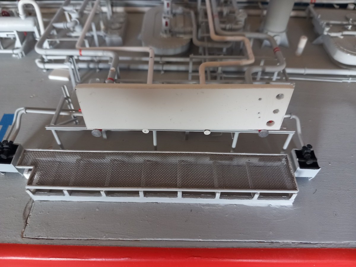
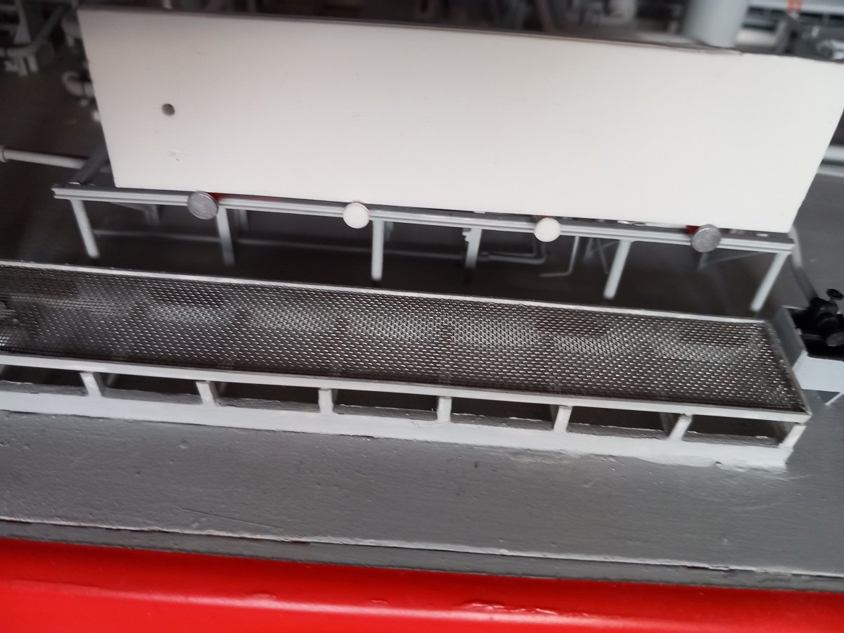
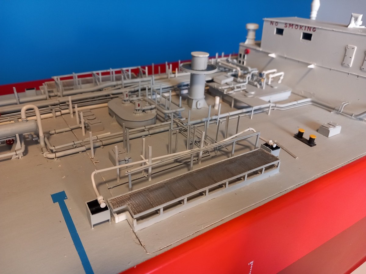
Waited to respond until I had something to show. Sorry for trying to put years of operations and many courses and manuals in a single post... I guess that was a bit much. In any case, as mentioned before, the first liquid line was the hardest as I had to line it out, get a good length etc. Once this one was done (and for those paying attention, in the last picture it had already its end flanges and orange painted extremities in place), I could continue with the others. I was very reluctant to glue it in place, due to so many things that need to line up at one time, that I didn't glue it in place for a long time. Although I wanted to continue aft with the vapor line next to my finished liquid line, I decided not to do that. Although everything is far from perfect, I had a feeling that the longitudinal distance between the manifold flanges would be very important for the overall view of the model. I therefore went ahead with the aft liquid line. Once that was done, I could go towards the center and make sure those distances were at least symmetrical. Again everything was laying dry fitted for a very long time, until I was sure that I had at least the space to cram in the other lines. I then glued the two liquid (orange tipped) lines in place and continued inward with the vapor lines etc. Here you see how I lined up all manifold flanges to be at a straight line transversally. Because I had the two liquid lines fixed, I could use a straight piece of styrene touching the flanges. I then marked the edge of the "new" pipes and cut them off at that mark. Once I had the flanges on on one side, I then used that piece of styrene against all flanges (with the white pipes still dry fitted) and used the same trick to mark out the other side. Then I cut that side and glued the flange. Up till that moment I had the "flanges", small rings, that I needed for valves, loose on the pipes. Once the flanges were in place, I could measure and glue the first flange for the first valve and so on. And a bit of extra. As you can see on the liquid manifold ends, there are two valves. 1 is manual, with a wheel (inboard), the other is hydraulic (outboard), with a big actuator. The manual valve is called a double shut valve and is installed because a single valve can leak, chances of having two valves leaking at the same time are much smaller. Since the liquid lines can go quite high in pressure, this is a requirement for liquid lines only. On the vapour line you can see there is no more manual valve behind the hydraulic actuator. The high pressure line also has a double valve (more work for me again). I've been thinking of making the manifold flanges bolted, in a similar way as the strainer lids. But eventually I decided against it. It would probably be out of scale, take a long time to make and I had already used blank discs as end flanges on other parts of the vessel, so it would be out of the normal to have them with bolts here. And last but not least I tested with a paper template, the walkway that's supposed to come on top. To my greater surprise (I had to make some things slightly out of scale and expected the accumulated error to be quite large), it fitted quite well. I will make a cardboard adapted version of this catwalk before I make the final one in the same way as I made the driptray gratings.
-
Not really my main interest, but I'm keeping an eye on this one for quite a while now. It's a funny hull shape and brilliant planking job!
-
Well actually, I doubt that. The reason for such slow promotions is often just long retention due to good employment conditions (if no one leaves, there's simply no place to promote anybody) and I consider time for model building etc. part of that. Additionally there would be training/certification requirements. To get a master licence it takes sailing time in rank and as officer of the watch (navigation watch that is). Often on such special ships, the time onboard is not fully considered as "sailing time". It might have a reduced validity of 50% compared to real sailing time. In the past this was the case for some dredgers as well. I've also encountered a system in offshore where the sailing time fully counted to retain a valid licence, but could not count for upgrading a licence. That of course resulted in a rather old crew, where all officer candidates already had their master licence.
- 300 replies
-
- 6
-
-
- lightship
- Feuerschiff Elbe 1
- (and 1 more)
-
oh sorry, got confused with Keith's Trinity House lightships. Propulsion or no propulsion doesn't make that much of a difference in this case when it comes to shipboard activities. You also stand a higher chance successfully fighting a fire with 11 or 12 than with 3...
- 300 replies
-
- 5
-
-
-
- lightship
- Feuerschiff Elbe 1
- (and 1 more)
-
I would assume there was quite some maintenance. Although there was no propulsion, they'd still have generators (need to keep that light on), which then means they'd have a fuel system, starting air system, fresh water production (or bunkering), sewage system, etc. All of that requires maintenance. Additionally I'm not sure if they had pneumatic chipping hammers, if they didn't, they'd have to chip with manual chipping hammers, which really takes a long time to do properly (in fact also also with pneumatic hammers). Cosmetic maintenance would therefore also take a lot of manpower. Additionally there is taking provisions, spare parts, bunkering, communications etc. Pretty sure they could keep themselves busy, although it would look to me like an end-of-career/retirement job considering the lack of prospects and for local people the idea of working closer to home.
- 300 replies
-
- 5
-
-
- lightship
- Feuerschiff Elbe 1
- (and 1 more)
-
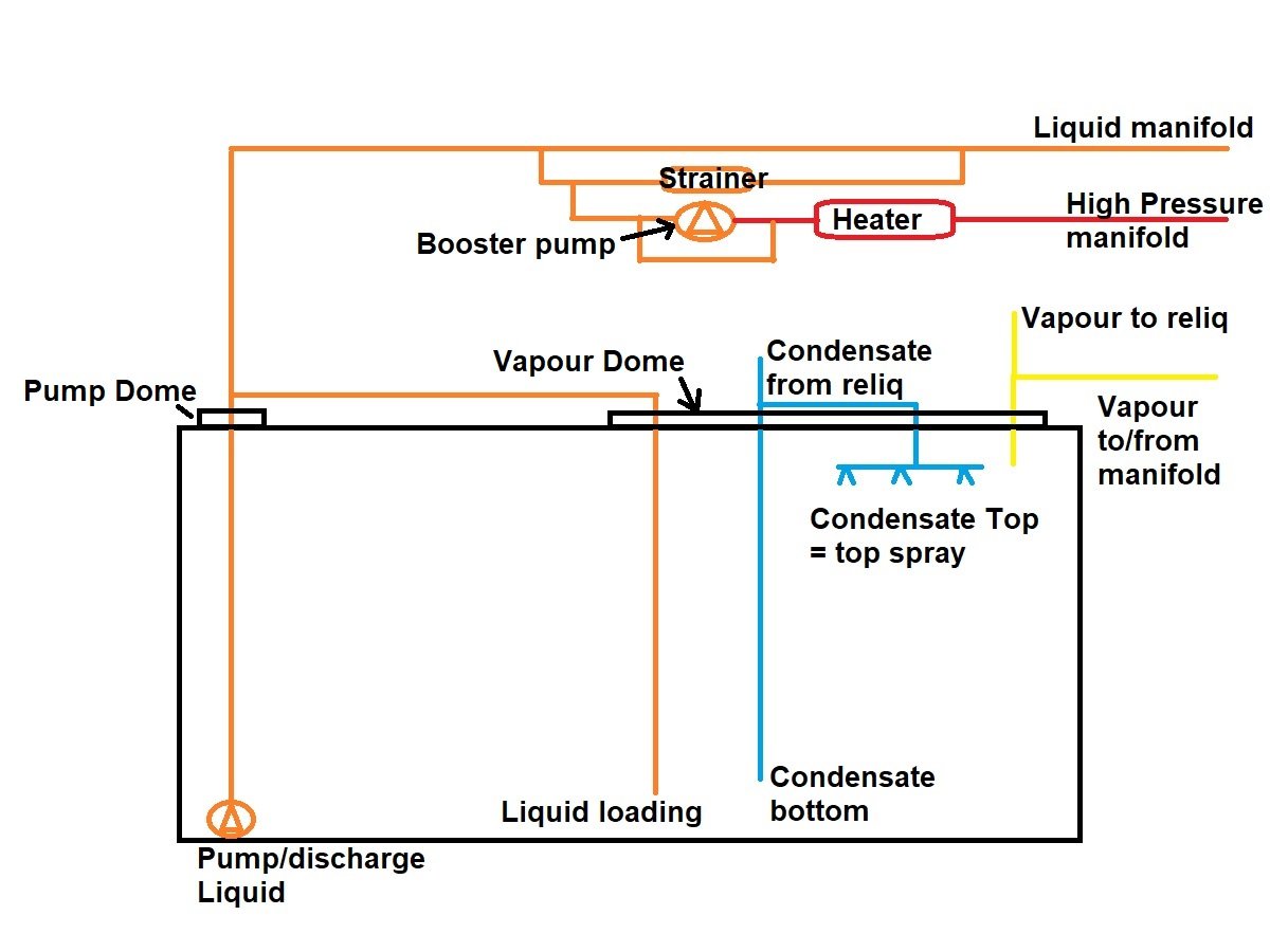
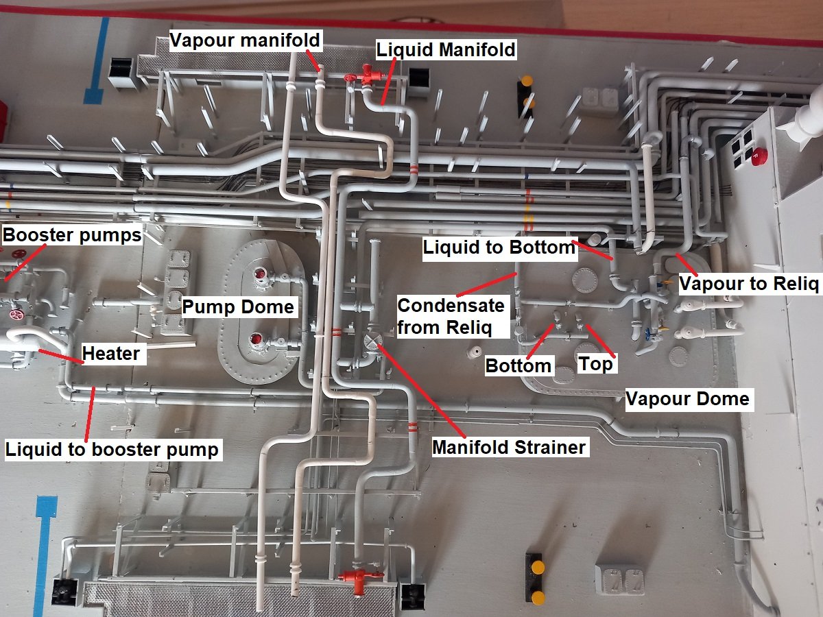
Well here we go then. Hope this clarifies a few things. Always a big difference between a regular diagram and the actual construction. A lot of complexity is added simply by having those 2 fully separated systems (marked on the lines by a single line or a double one). The diagram is a single tank depiction with only a single pump. To make things worse, the tanks are split longitudinally in 2 halves for stability reasons. 1 pump is located in each half. The top and condensate system however, are connected, to keep the pressures equal (so you can't mix put two products in 1 tank). For loading there is a (small) valve located between the pumps so you can equalize the liquid levels. The different lines on the drawing are colored in the same color as the lines on the ship, so that should be clear. I believe I marked everything from the drawing on the picture. This drawing would only explain loading or discharging, but there are additional lines that are used for "special operations", eg. dry docking, changing cargo etc. Normal life cycle would be something like this: - Dock: Ambient air - drying the tank (dry air) (ambient temperature, vessel underway to loading port) - Inerting the tank (removal of oxygen to avoid flammable mixtures when loading flammable gasses) (ambient temperature, vessel underway to loading port) - Filling the tank with cargo gas (depends on which gas you will load, done to remove the inert gas from the system, since that doesn't work in the reliquefaction plant later on and it would still retain some moisture in the system, which you want to avoid) (ambient temperature, arrived in either special port to receive small amount of cargo, or in loading port itself) - Cooling down of cargo tank (going from ambient to loading temperature using condensate line top spray) - Loading of cargo When going to dry dock: - discharging last cargo as much as you can (cold temperature) - sending warm gas to the bottom to remove last liquid cargo - warm-up of cargo tank to warm up the insulation and tank walls - inerting of cargo tank - aeration of cargo tank - once gas free, vessel can enter dry dock In the above sequences a lot of different non-fixed connections are made between the pipes and I'll avoid pointing all those out in detail. When changing cargo it's practically the reverse. First you prepare the vessel like going to dry dock and then you prepare it for the next cargo, much like after dry dock. With propane and butane you can often cheat a bit, but you can't do that when going from propane to ammonia etc. Hope it's a bit more clear, let me know if you want more details.
-
I'm definitely not designed it myself, I'd make it much simpler and wouldn't take 10+ years to build it if I were 😁. I have some plans, but a General Arrangement plan doesn't really show the whole piping. It mainly just covers the main pipes and does give a good indication of its location and dimensions. I combine that drawing with a LOT of pictures, 100's of them (much like the manifold picture I posted previous post). That's also why the research takes so much time. For a lot of the details I need to scan through the pictures to get an angle on some details, then determine what size they are and what their actual location is compared to their surroundings.
-
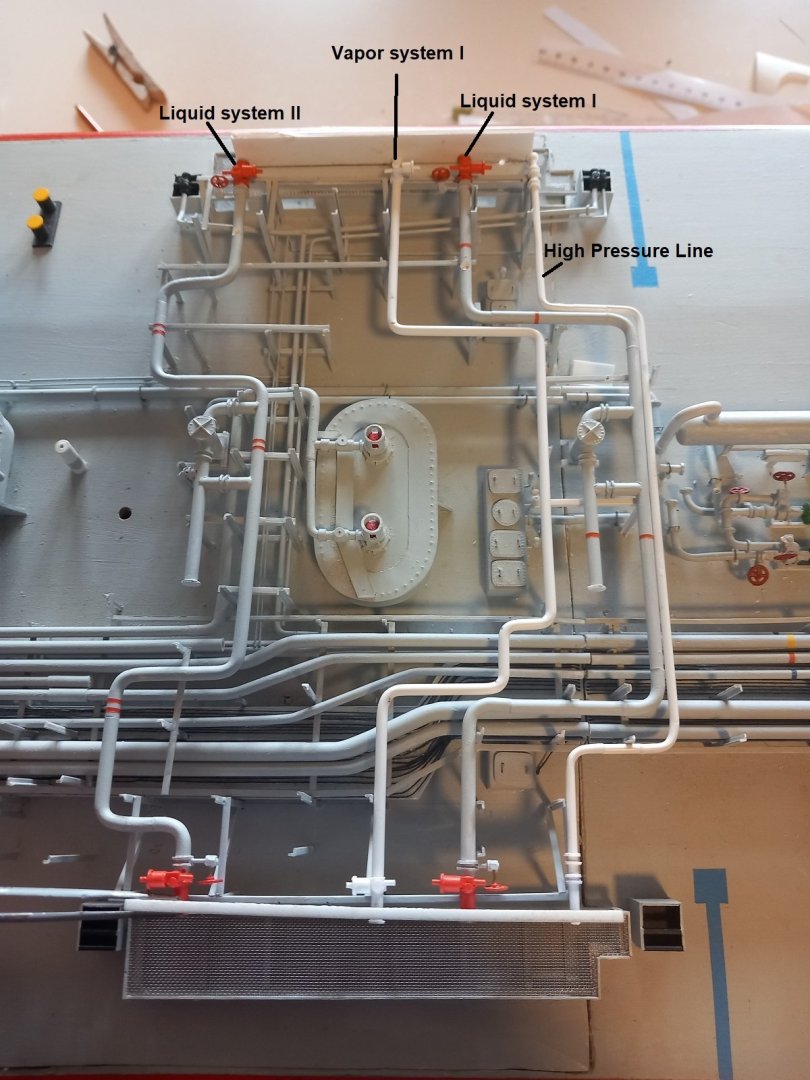
Hi Phil, it's actually quite a while ago that I served on this ship, around 15 years now... But technology is technology, so I remember most of it. The U-shapes are indeed to absorb expansion. I've always wondered why they had two bends on the transverse manifold lines, but during construction of this model it actually appeared to me. The liquid enters from the longitudinal lines through that strainer line into the transverse line, somewhere around the center. You load or discharge only on 1 side of the vessel, portside or starboard side is connected to shore, that means the other side is blinded off and contains a gas bubble. Since there is no liquid entering that side, it doesn't cool down (or at least much less so). Due to that effect they put one U-shape on each side, so you certainly pass the cold liquid through one of the U-shapes. And I agree on the complexity, I believe a fully rigged model is in the same league, you're basically also taking a lot of small steps to slowly build up that final complex appearance. In a very similar way you have to plan which lines to do first and which ones later. Thank you very much for actually saying that Ian. It appeared logical to me that people could pick out the new stuff on the pictures and relate that to the text. Now that I know it's not that obvious, I'll work on that to make it more clear. I'll take an overview picture today and mark the different parts on that overview. I've also been thinking to make a small diagram showing the piping and flow, perhaps I'll do that as well if people would be interested in that.
-
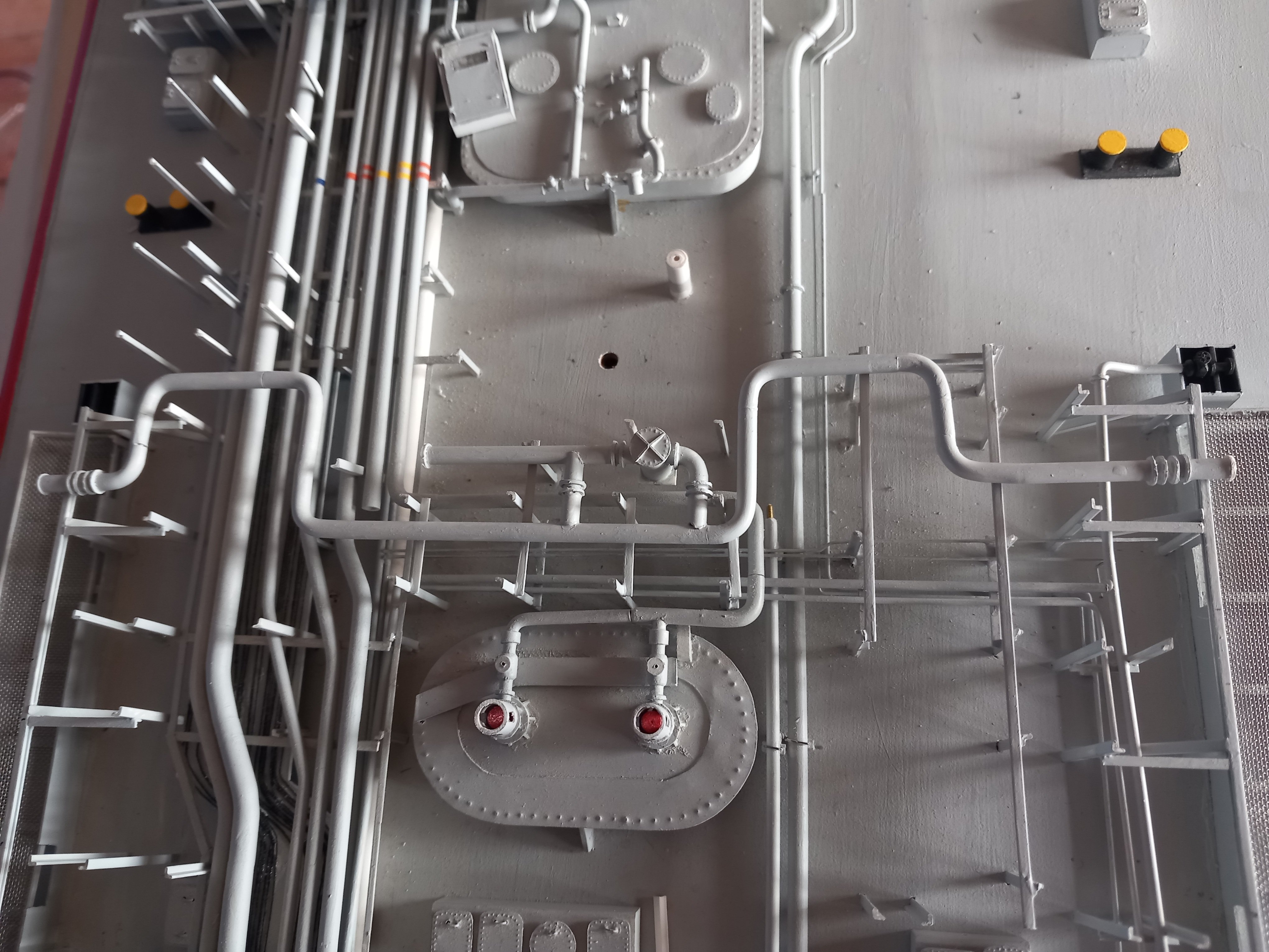
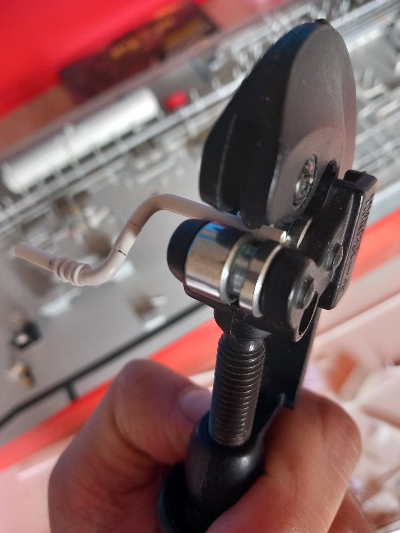
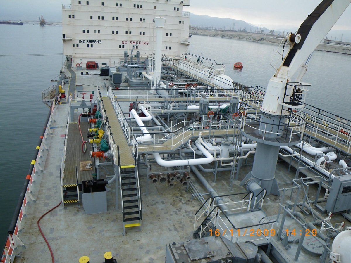
Not sure if you're talking about the model, or the real ship... On the real ship, as Roger explained there are quite a few "rules" that determine how this is all set up. A side note to that is that there is a certain pecking order in the design. With so many people involved, I would assume somebody designs the hull, then the "cargo guy" can do his thing and then the next one in line etc. That does complicate a lot of things for a lot of people I assume. The engineer who had to design the fresh water system and piping for example, was probably the last in line and had to arrange his piping from the fresh water tanks to the manifolds as well. On Chaconia I noticed they had dismantled most of that piping, using only the aft connection to bunker fresh water when required. The same counts for hydraulics etc. The engineer who designed the cargo system put some hydraulic valves in his system, but probably did not design the run of hydraulic piping. So in some cases, we do wonder why they did what they did, the way they did it... Your remark did remind me to put a picture of that real manifold in here, since I don't think I posted that yet. So yes, I still have a lot of work to do. On the other hand, it does show the real paint job on those ships, a reason I'm not too concerned about painting on the model. 😂 The big white pipes on the manifold are actually the liquid lines, they are frozen due to the cold liquid being pumped. As mentioned before, that liquid line was going to take a while. Once I have that one, it'll be easier. Below is that strainer and it's by-pass etc. To adjust piping and get a staight cut I use my old pipe cutter. It goes only down to diameters of 3mm, so it can't cut through, however, the cutter does leave a nice straight cut mark, which I can later on follow with a knife to get a 90° cut. I thought a while about the cross shaped reinforcement on the lid of the strainer, but decided it really was required to give a proper impression. The lid itself is a litho top with the bolts punched in, backed by a 0.3mm styrene plate to give a little more thickness. The cross is made up of 0.3mm styrene. The strainer body itself also has support beams, but those will be added later, in an opposite fashion, since you can't line up everything from bottom to top. Additionally there is still a pipeline that needs to go from this liquid line down to the booster pumps (part of that pipe can be seen near the deck level, with a piece of brass wire sticking out). I am nearly there when it comes to this pipe.
-
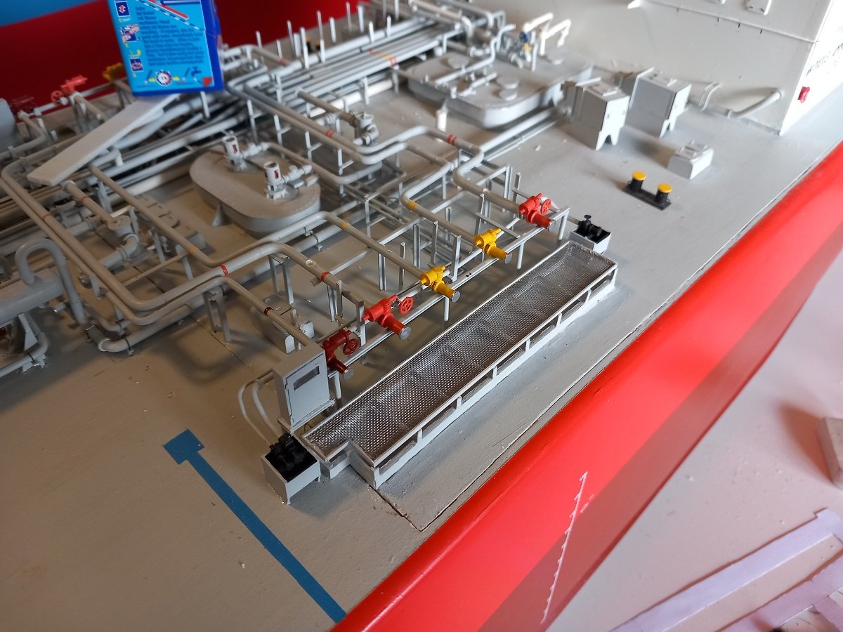
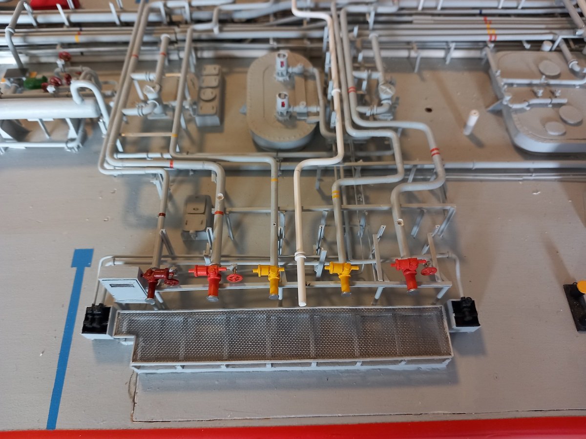
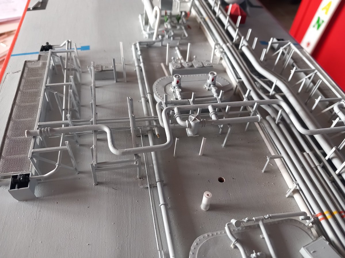
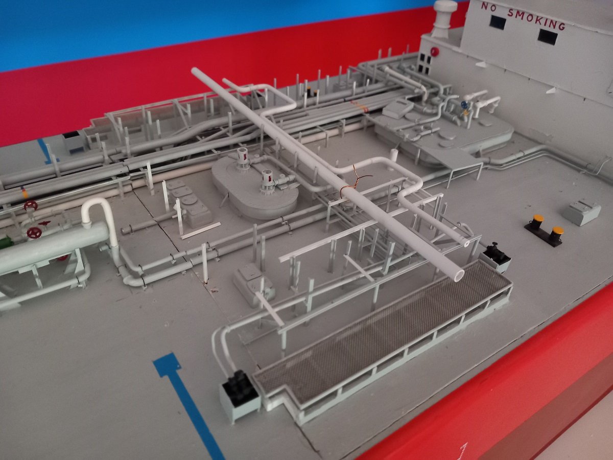
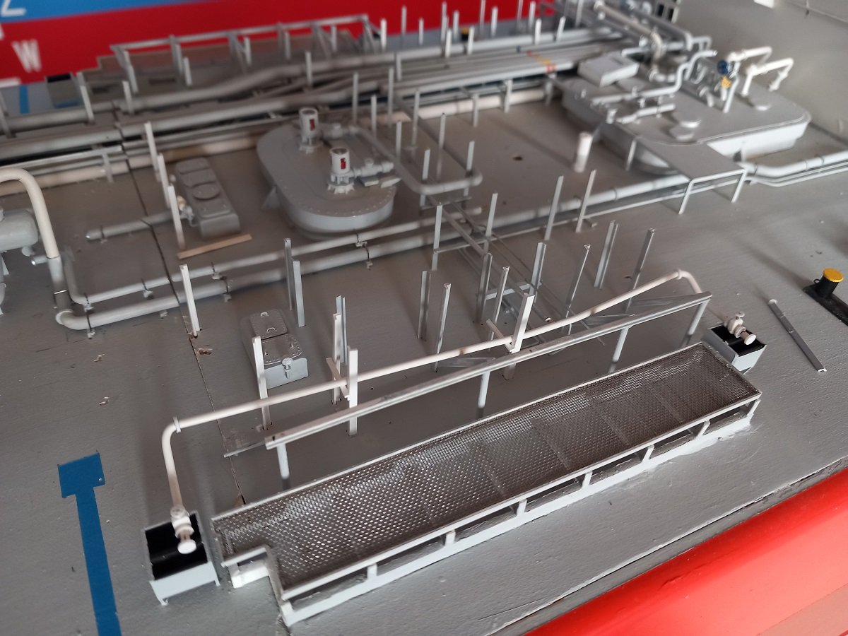
So now both bunker manifolds are in place. Not on Portside, because on that side the bunkerline is actually crossing over the cargo piping (due to the longitudinal piping rack). So first up is the transverse cargo piping and then PS HFO bunker pipe (DO pipe does run underneath the pipe rack, logics 🤪...) First was lining out the support bars for the piping. I wanted to start aft and connect to the cargo heater system, but decided against it and started on the forward piping. Aft part will be more difficult as it's the part going over the edge of the hatch. It would also have restricted my access for the forward piping probably causing damage to the aft piping, so, first forward. Since I had the two supports of the manifold piping in place, I could now put a transverse pipe in place to line out the supports. I used normal straight pipes. I'm also building the bent cargo piping on a flat surface to have the bends in a single plane. As you can see I held the supports up with some copper wire attached to the beams. I used CA on 1 or 2 vertical supports and normal plastic glue (= slower curing, but stronger bond) on the rest of the supports. One of the supports near the center was a bit angled in, not leaving enough space for the aft (Inert Gas manifold) pipe to pass. I used a spreader on top of the pipe to keep them at a correct distance while using the support to keep at the proper distance. Seems to have worked. The 3 forward pipes in place. Most forward is Liquid System 2, followed by Vapour System 2 and Inert Gas line. For normal cargo operations the Vapour Return is not used on LPG tankers. Normally the reliquefaction plant will liquefy the vapour coming from the tanks and send the liquid/condensate back to those tanks during the loading operation. If for some reason the reliquefaction plants can not handle the vapour and pressure rises too much in the tanks, the vapour return connection can be opened towards the terminal, but in that case the vessel will have to pay a fine (normally vapour return is sent to a flare and is therefore considered a loss). So it's almost always connected to the shore terminal, but rarely used. This may look like major progress, but it's not. As you can see I need to make a lot of flanges for valve connections on those pipes. Lining the pipes up transversally and longitudinally is a challenge as you need to keep the longitudinal distance on the manifold equal, while you also need to keep the bends in the correct places. Again a lot of fitting, adjusting, fitting again etc. The forward liquid system also has a big cargo strainer connected. During loading, you normally load through the strainer (you don't want dirt in your tanks), while during discharging, this strainer is generally bypassed (but often stainers are using inside the manifold connections). Of course this means you need valves to by-pass this strainer, so again more valves to add on the system. The stainer you can see already on the starboard side, unpainted. It will take a while before I finish these lines, but once they are done, it will be quite a step forward to completion of the vessel.
-
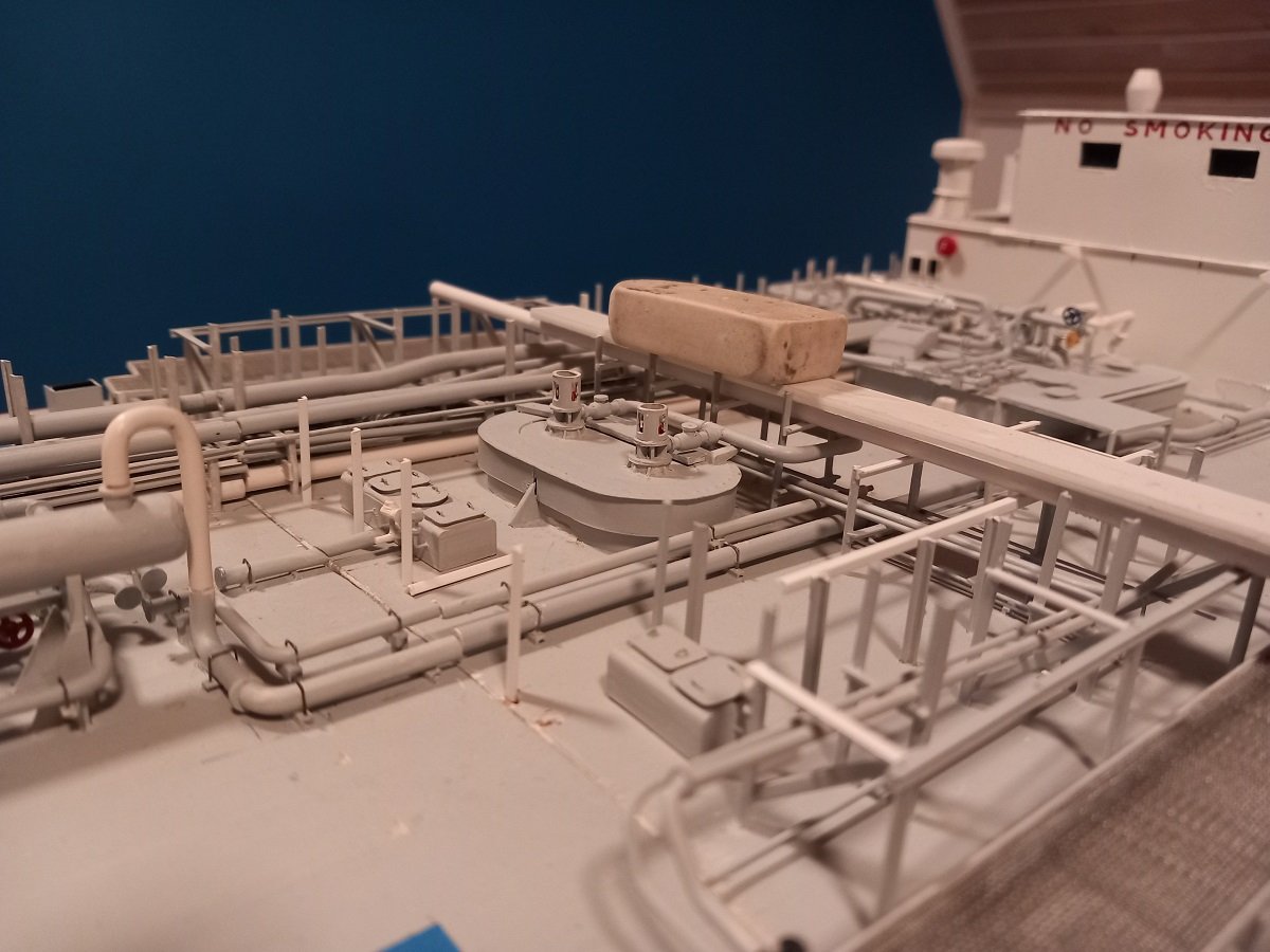
Been a while again, but there's no messing with the 2-piece quotum. Although it doesn't look like much, I'm busy with a critical pipe. One that scared me a bit (= stopped at that point in the past) due to its complex shape. It's the bunker manifolds. 2 pipes are there, an HFO (Heavy Fuel Oil) system and a Diesel Oil system. They are shaped very strangely, but I assume they did it that way to make sure that the line can be drained properly to the tank, so in case of a leak on the manifold, there would only be a limited amount of oil that could possibly leak to the flange side (that is at least my theory for this odd shape). A long while back I made preparations for this system since I put a 1.5mm rod with a 90° bend already in that manifold. I would not be able to place such a pipe afterwards. I was a bit obsessed with having as little joints in those pipes as possible and always tried to make things from 1 piece. In the end, the installed pipe didn't have a good 90° bend and didn't want to go in place, so I clipped it near the bend. Made a proper 90° bend. I also could remove both pieces of the pipe that way and adjust their lengths properly without risk of damage to the rest of the construction. Having decided to do this, it allowed me to take the next step more easily. As you can see, it goes over the edge of the hatch, complicating things a bit more, as the pipe has to be properly sized and fitted, there's no way I could bend and glue the aft piece to the drip tray. Flanges and valves were dry fitted for testing. Here, handwheels are already fitted to the valves. I used 0.3mm thick styrene discs which I drilled out in the center and later on in the 4 corners. This pipe had to be painted and fixed in order to proceed with the transverse beams above them. Here it is painted and fixed in place. The forward transverse beams are in place, since the DO system only goes to the aft drip tray. DO system (Smaller capacity and diameter of pipe) is dry fitted here. The whole process involves a lot of bending, fitting, bending, mounting the hatch back on the ship to see for the drip trays, then removing it again to work on the piping etc. Once the DO system is in place, I'm ready to continue with the transverse beams and then I can proceed 1 level up with the actual transverse cargo pipes.
-
I think that about sums it up. Cruise vessels nowadays do carry larger engine room crews (because also the side jobs like sewage plant, technical issues in cabins etc are part of their jobs), but not anything like on United States. On modern merchant ships, notably the LNG steam ships, we had an engine room crew of around 7, mostly composed of: 2nd Engineer 2 x 3rd Engineer 4th Engineer (apprentice engineer, optional) Fitter Wiper Oiler Chief Engineer is an office job, much like Captain nowadays, so I'm not considering them really as part of the engine room operating crew. Of course these were fully automated engine rooms, unmanned during the night. Full of sensors with linked alarms that wake up the duty engineer if required.
-
It was fun. Rooms are ok, breakfast was really good. Kids also got a small plastic bottle with a special paper to send home in form of a message in a bottle. Location's great too, not too far from the Maritime Museum, and price was good compared to any other hotel as well. In the end we'll have to go back, since we didn't even have enough time for the guided tour. Not sure if you'll feel the same way if you've seen her in better days in her true element in the past ...
-
That's a great result on that lettering and portholes! I'm still amazed at the speed at which you can achieve such results.
- 300 replies
-
- 6
-
-
- lightship
- Feuerschiff Elbe 1
- (and 1 more)