JacquesCousteau
-
Posts
1,383 -
Joined
-
Last visited
Content Type
Profiles
Forums
Gallery
Events
Everything posted by JacquesCousteau
-
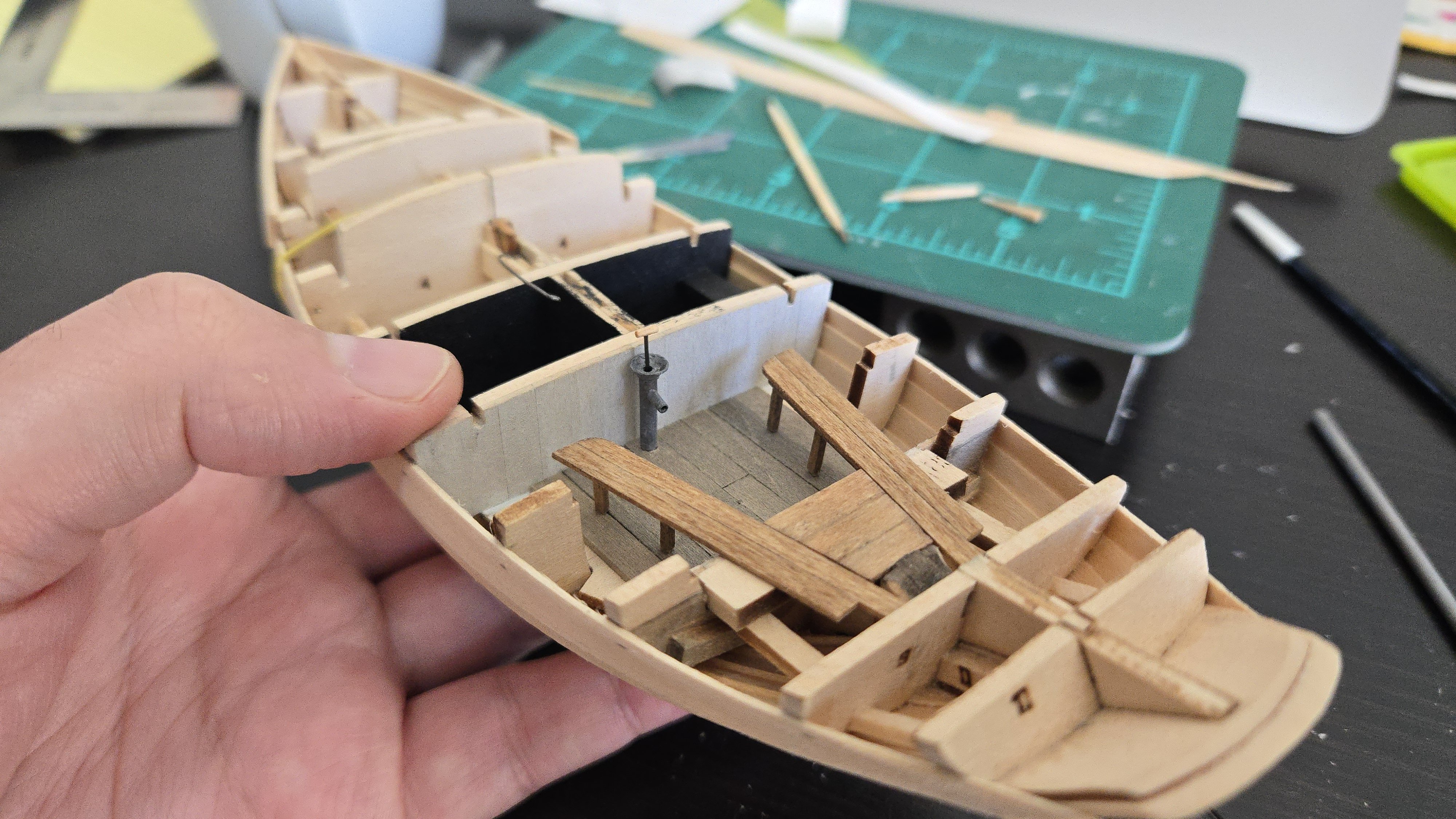
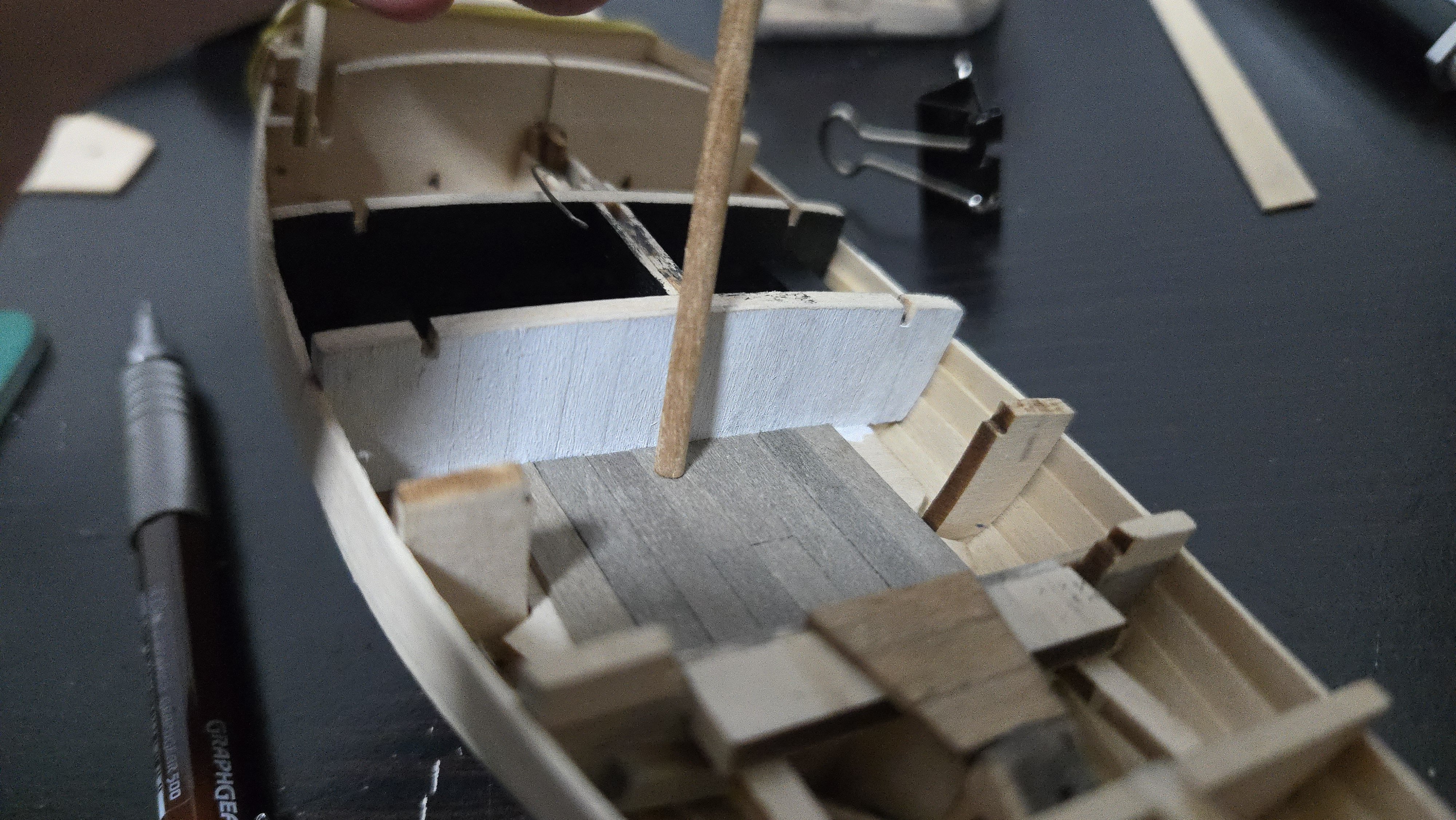
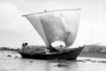
 Thanks, all! On the exterior, I shellacked the hull and lightly sanded to remove the raised grain. I also decided that now is a good time to add the rudder, as I'll need to paint it when I paint the hull. I first added a small brass pin at the bottom, that will anchor one end of the brass rod I'm using for the rudder shaft. It was then straightforward to add the rod, mark where to cut it, cut it, place it, and superglue on the rudder. The completed assembly currently can turn. In the cockpit, I decided to paint the frames and inner faces of the hull planking the same white that I used for the cockpit's fore and aft bulkheads. This was originally done with alternating layers of dark and white acrylic washes. This attempt turned out a little darker and grimier-looking. Unfortunately, the washes loosened the glue on several frames, so I ended up supergluing them back into place. I also added extra frame pieces coming up from the bench-level bulkhead and aft of it--I don't know if these will be visible, but better that they're there in case it can be seen. Next, the benches. For this, I was inspired by this photo of a Friendship Sloop, which shows a framework extending back to the frames. Source After considering how best to handle these and their delicate framework, I glued them in place. I then added the foremost horizontal beams, using tweezers to manuever the pieces into position and securely glued to the underside of the bench and to the hull/frame. Once those dried, I was able to glue one more plank on the back end of each bench. I then added an intermediate horizontal support at the level of the middle bench leg. After that, I added some low backs to the benches and around the rudder head housing. I also added a cap piece going over the aft bulkhead--it may be disproportionately thick, but it looks better than the bare wood (and it really shouldn't be very visible). With that, I think the cockpit is basically finished. Below, I placed the bilge pump, although I think I may just leave it off entirely until near the end of the build. I'll need to think whether there would be anything else in the cockpit--some sort of hanger on the bulkhead to securely stow a gaff hook? In any case, the cockpit has been a lot of fun to build, and I'm glad I decided to modify it from the kit design.


-
If you're interested in building it as a schooner, there's a very interesting build log that will probably be helpful: There are photos online that will probably help with mast/yard proportions, as well.
-
Very interested to follow along with this build!
-
You can also anneal it over a stove burner (provided you have a gas stove, that is). Very nice work!
-
Very nice work! Do you have any photos of the entire model?
-
Very sharp! Great use of jigs to get a precise and consistent fit.
-
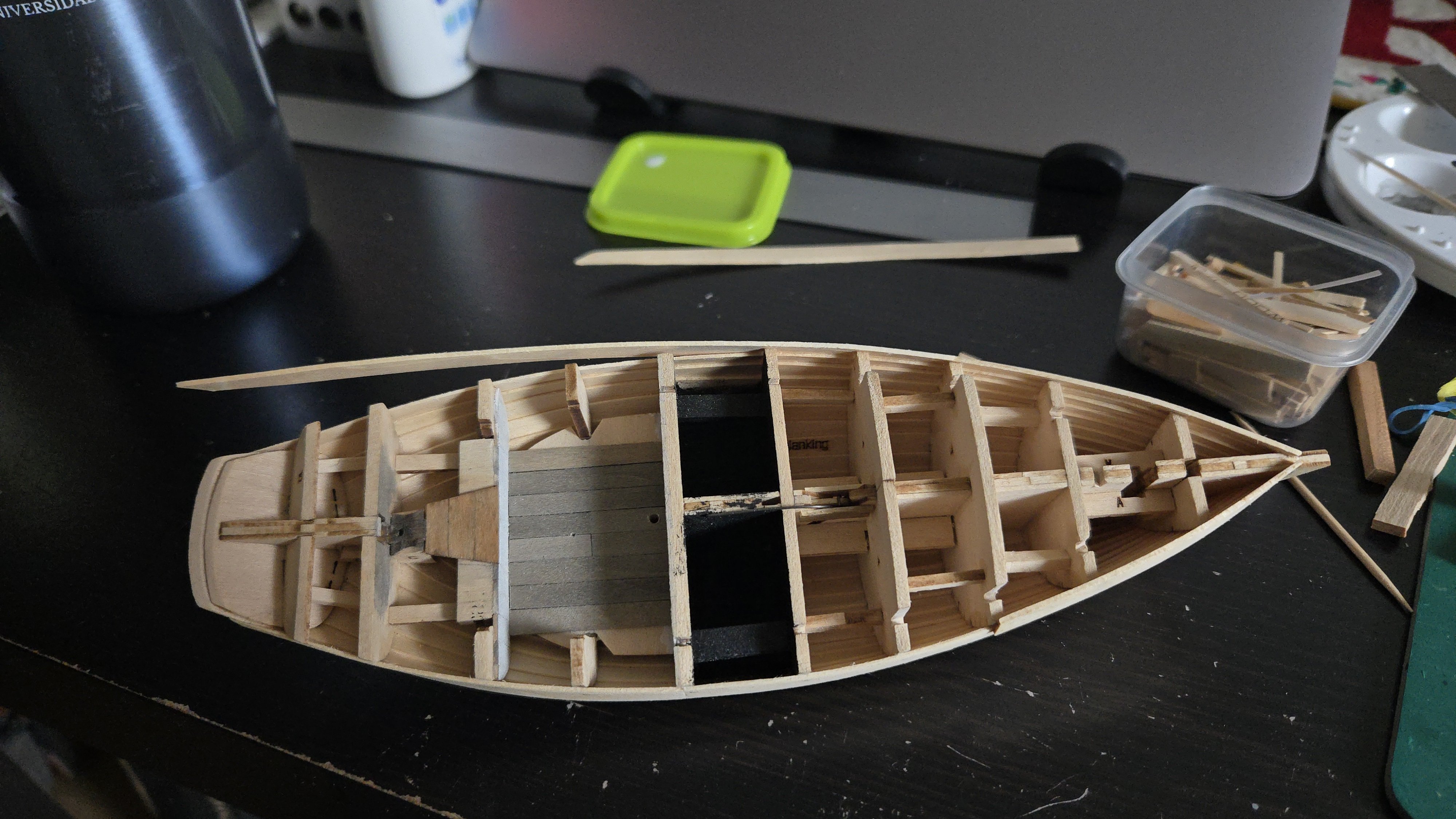
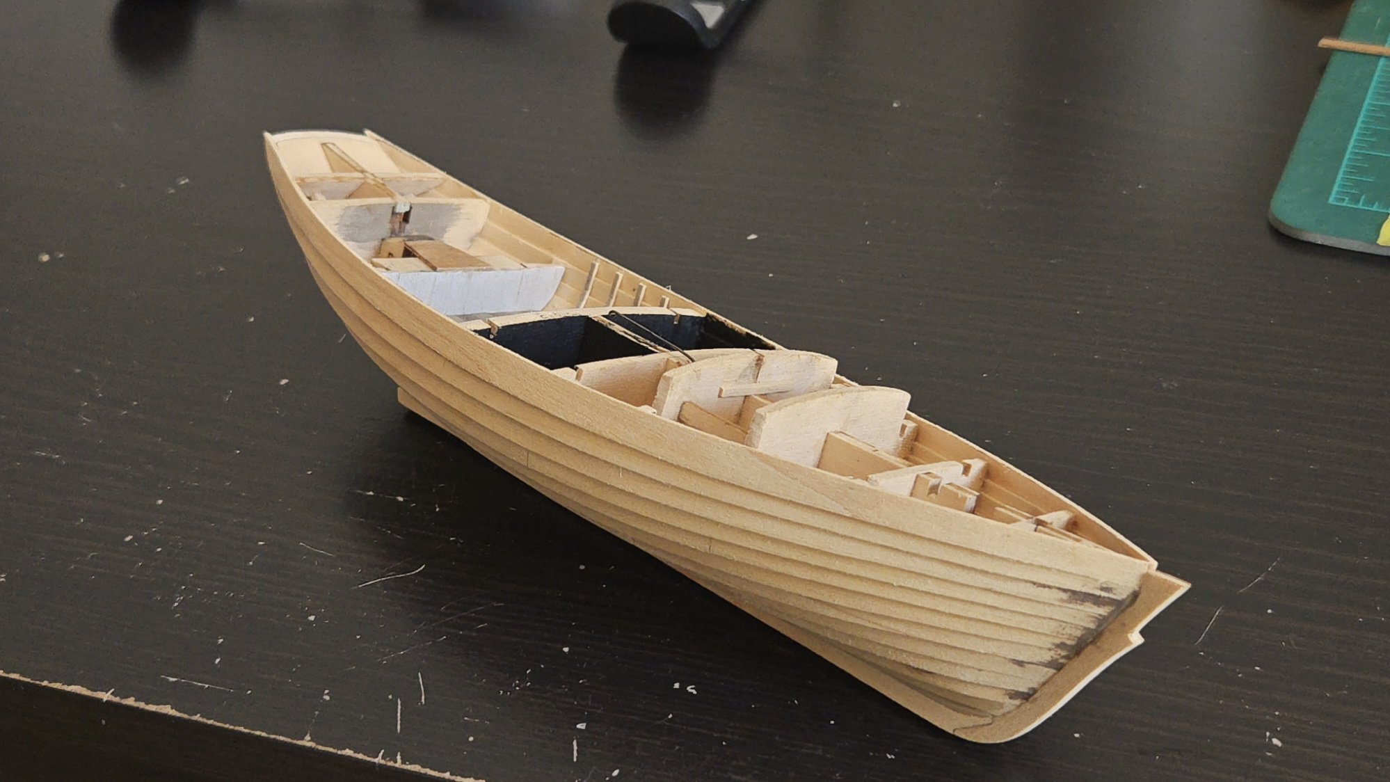
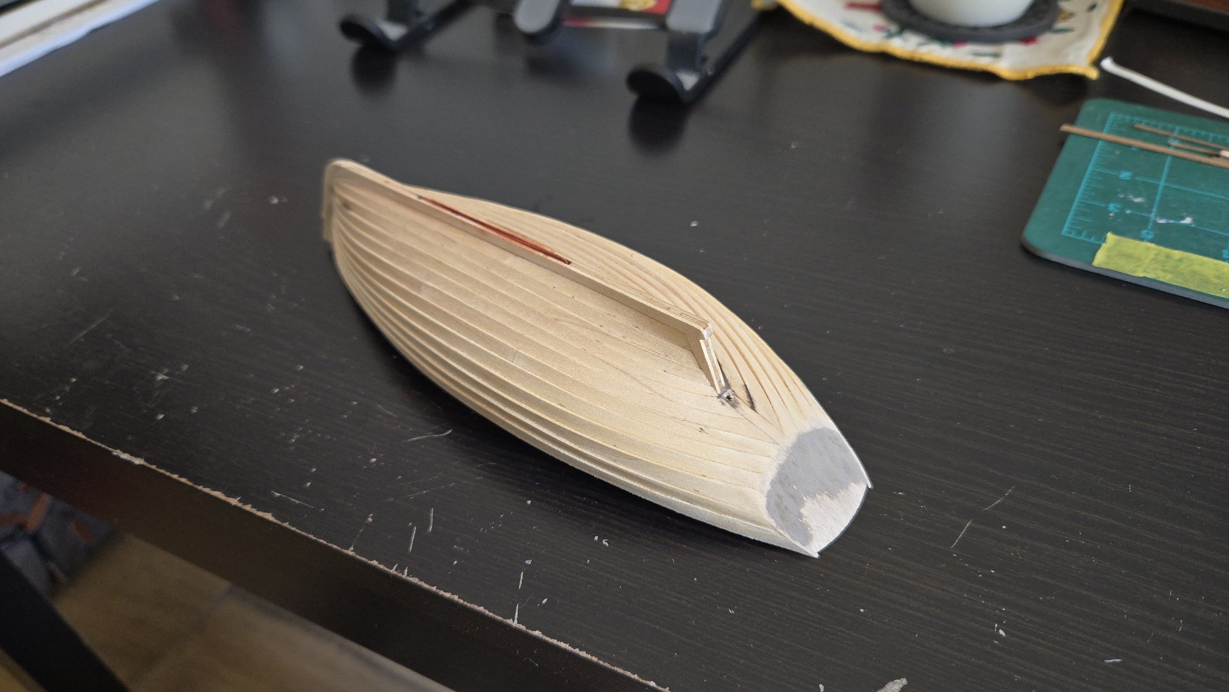
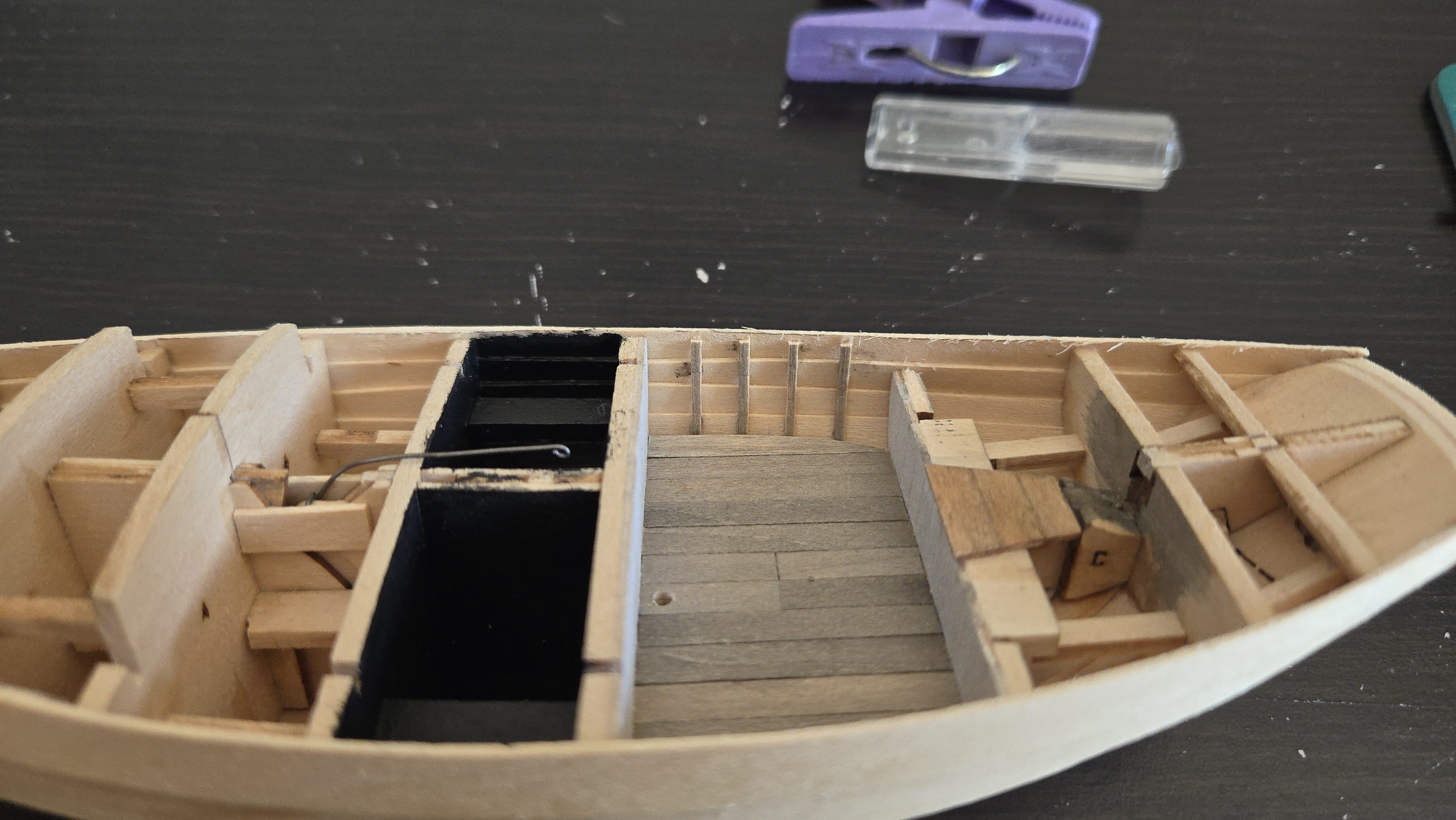
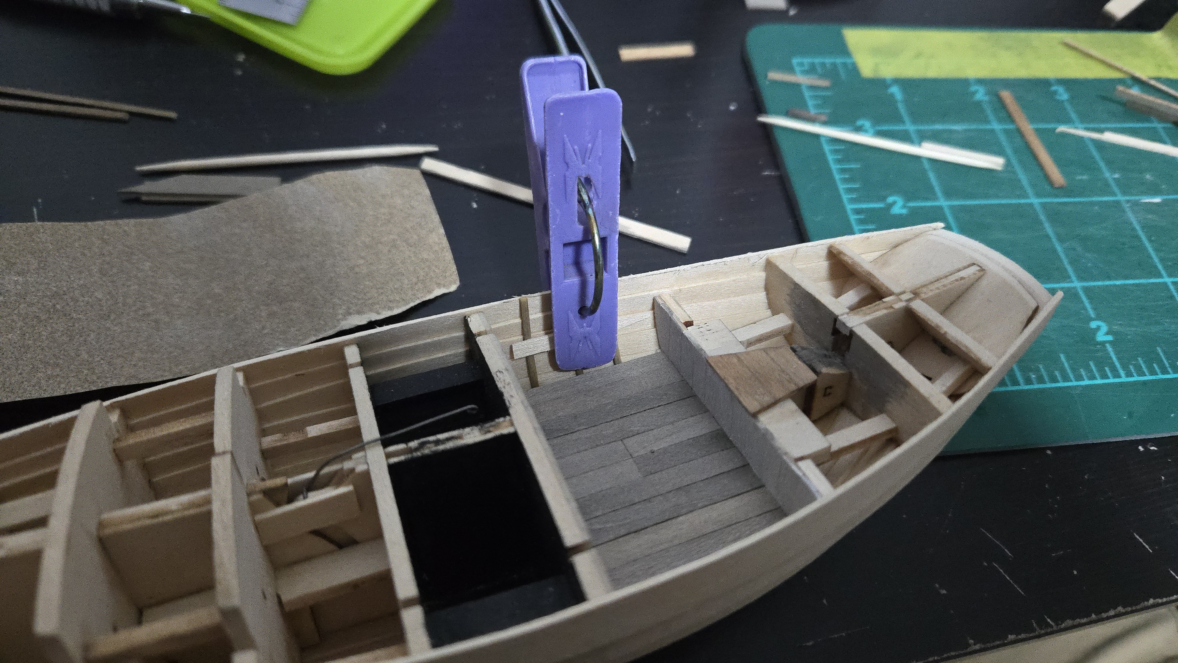
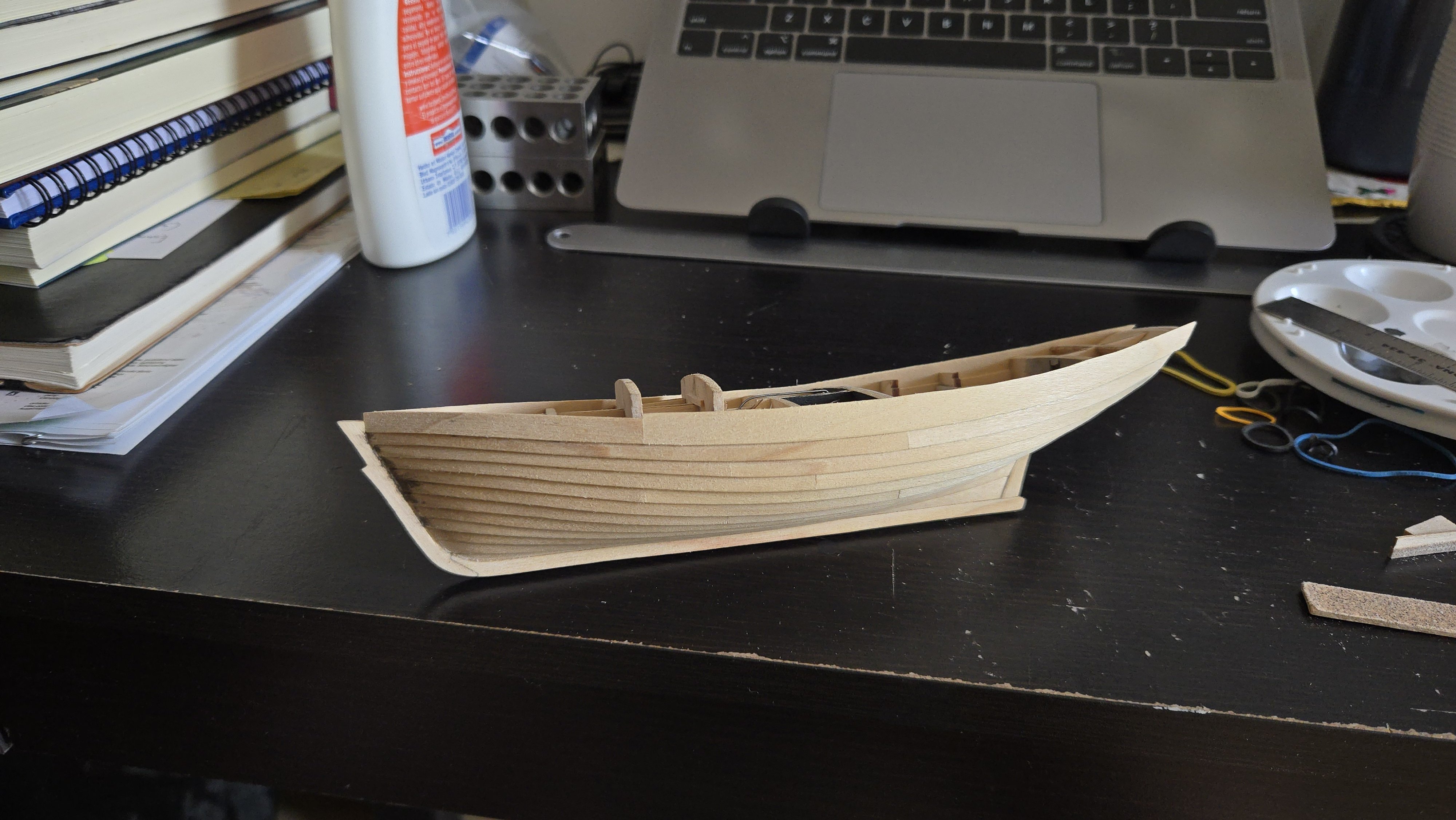
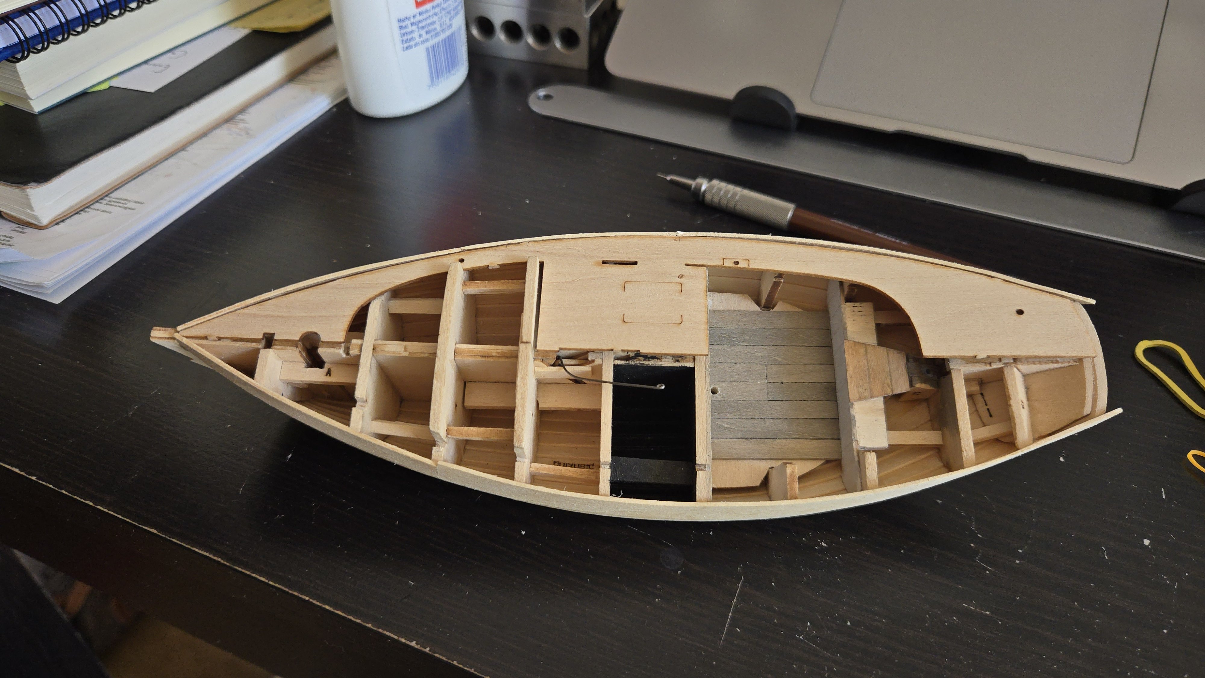
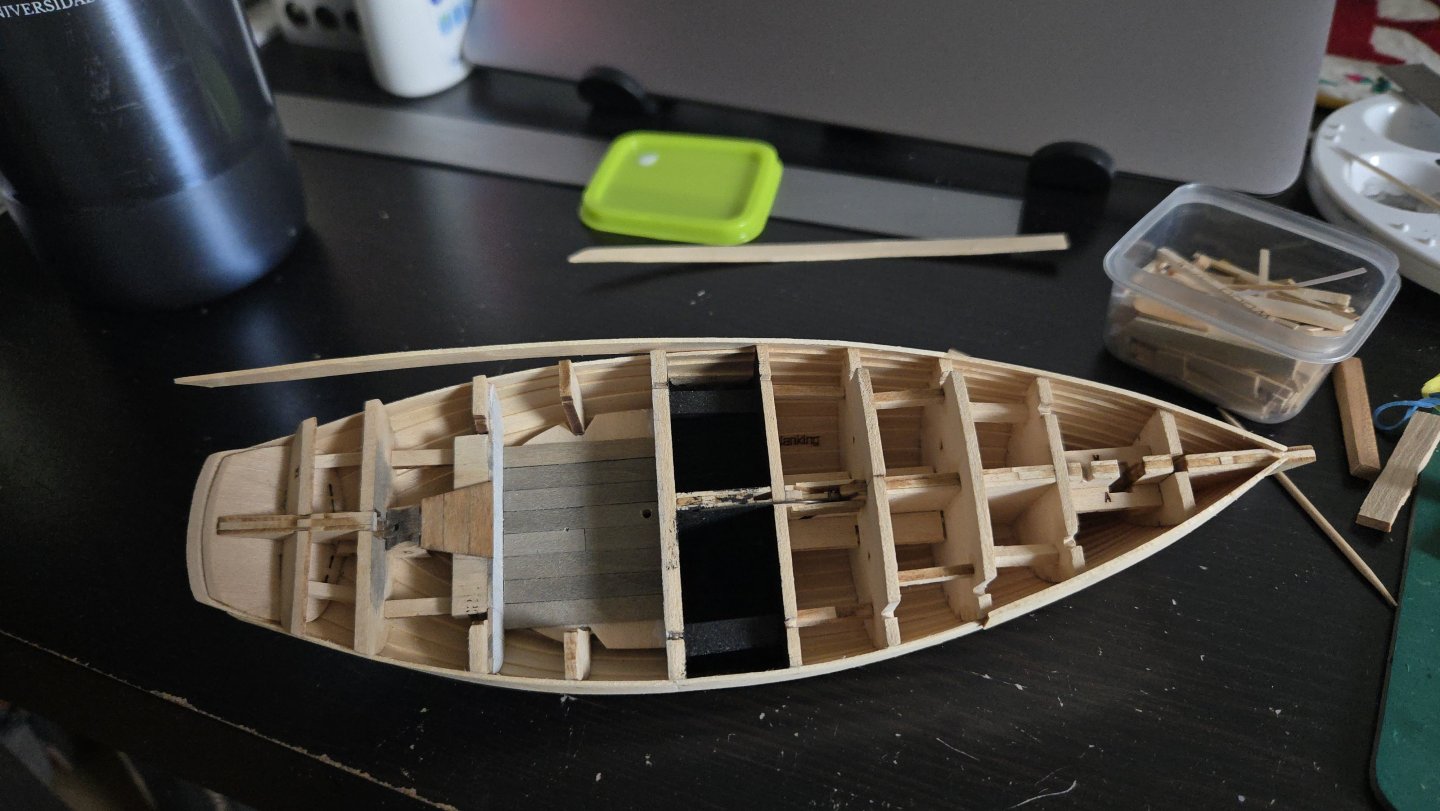
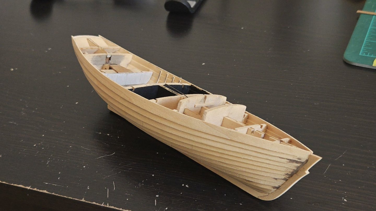
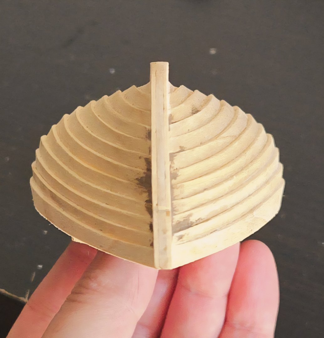
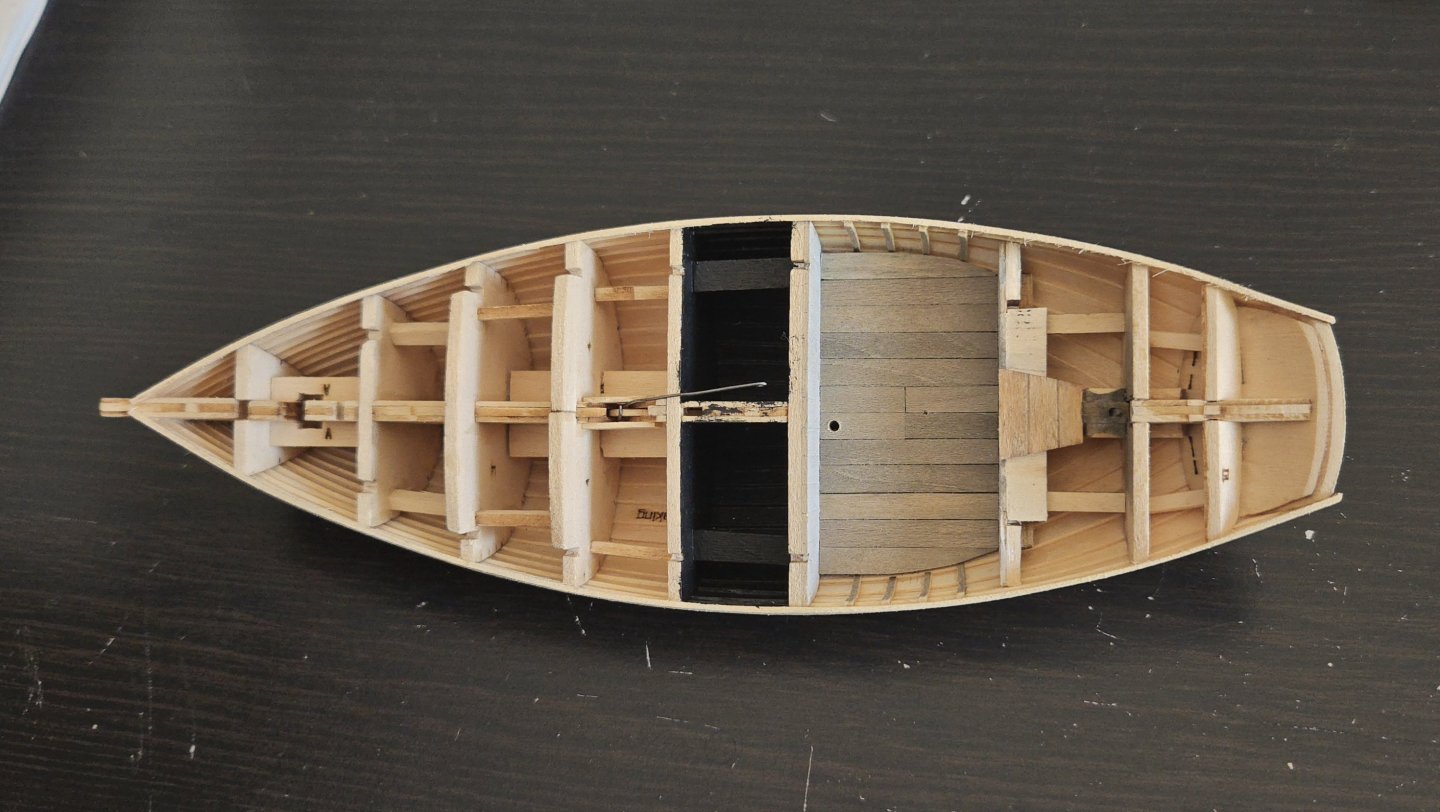
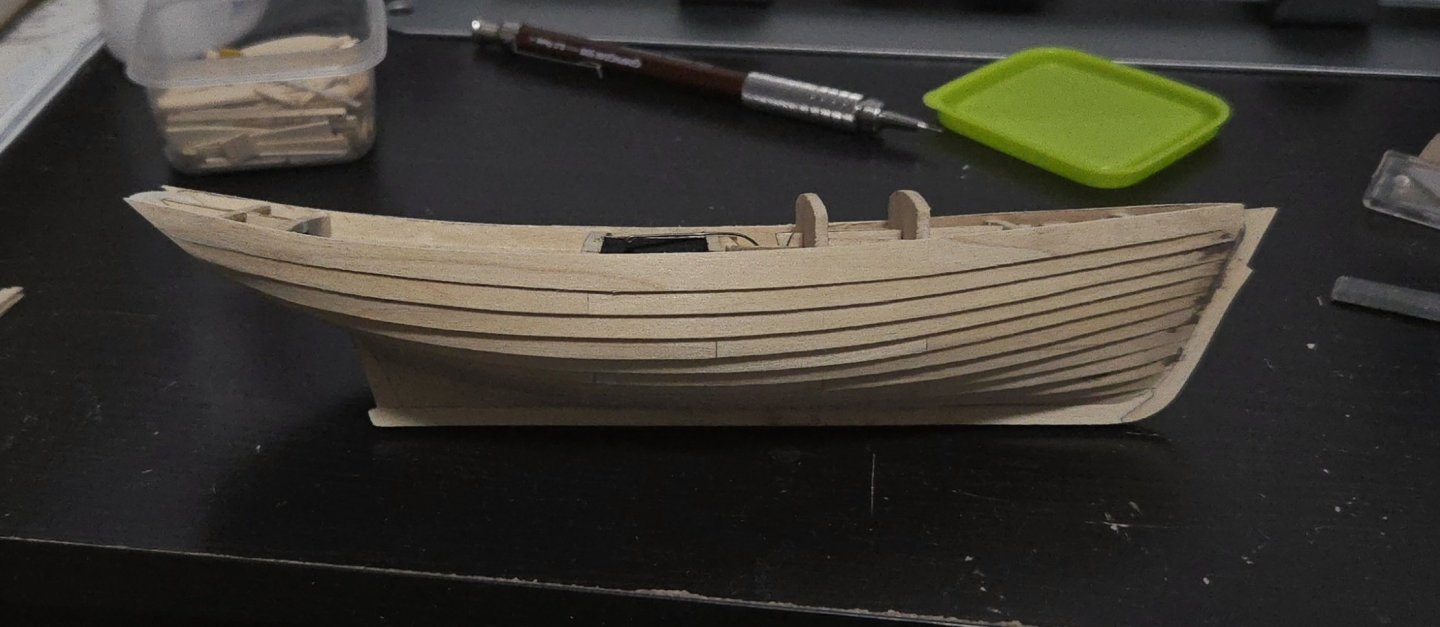
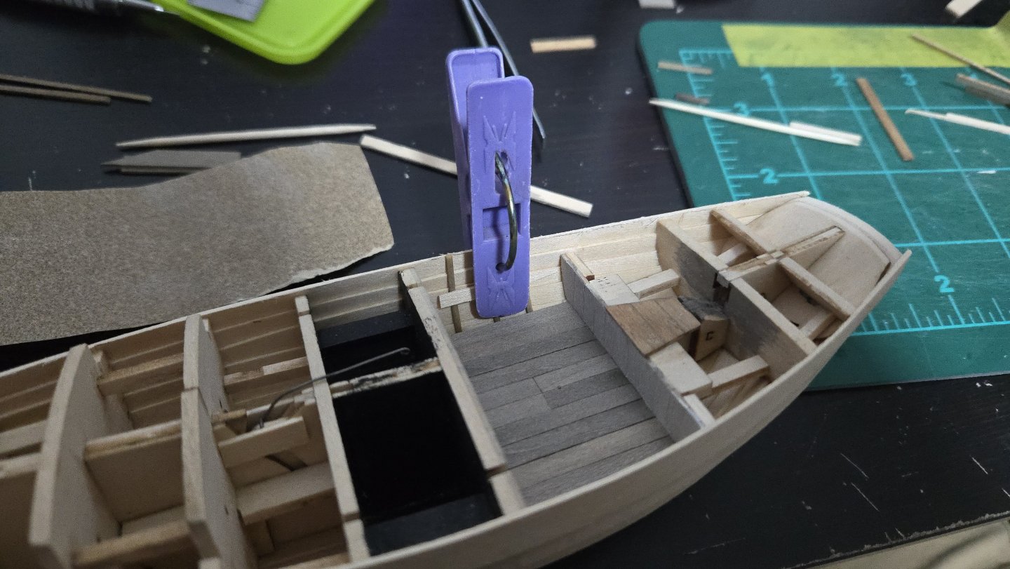
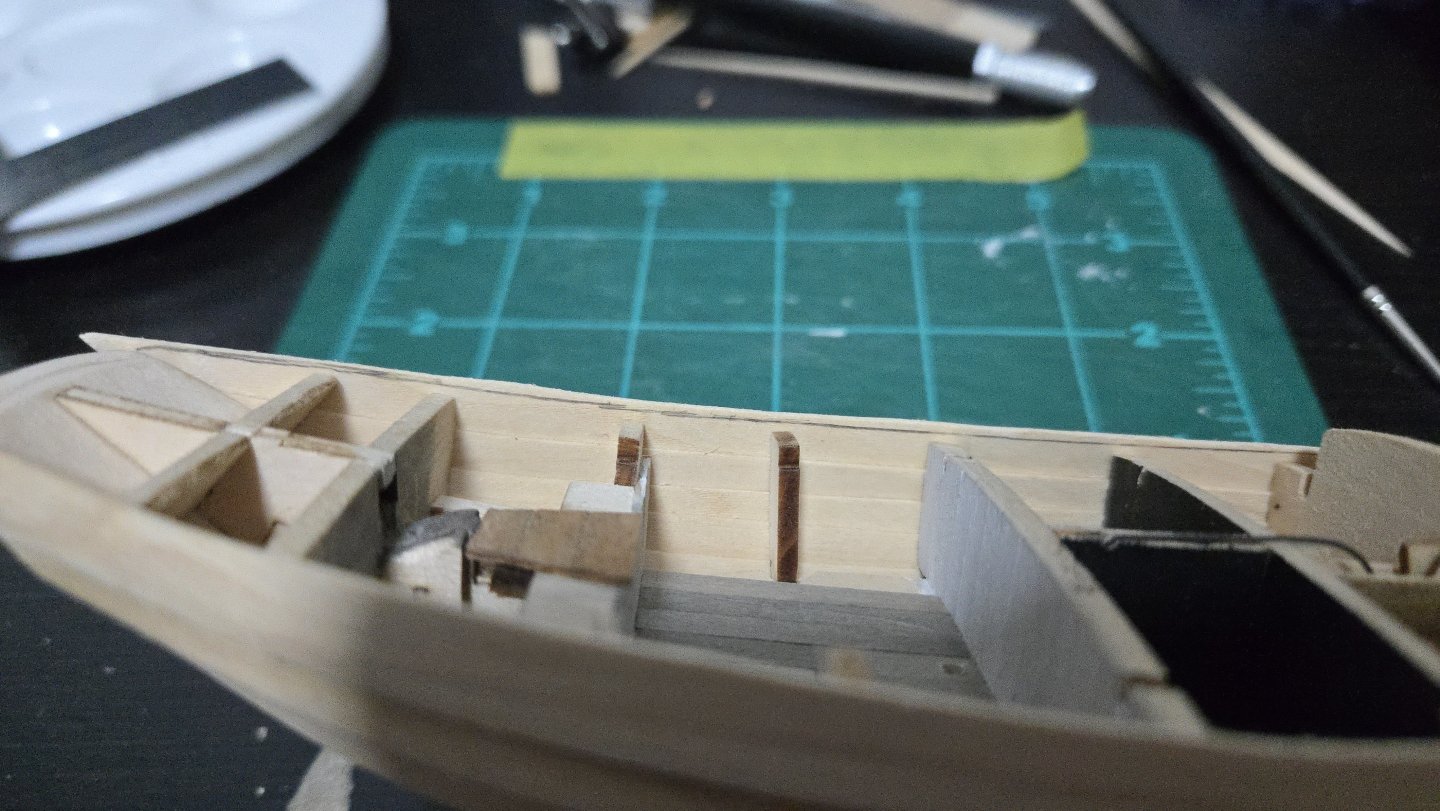
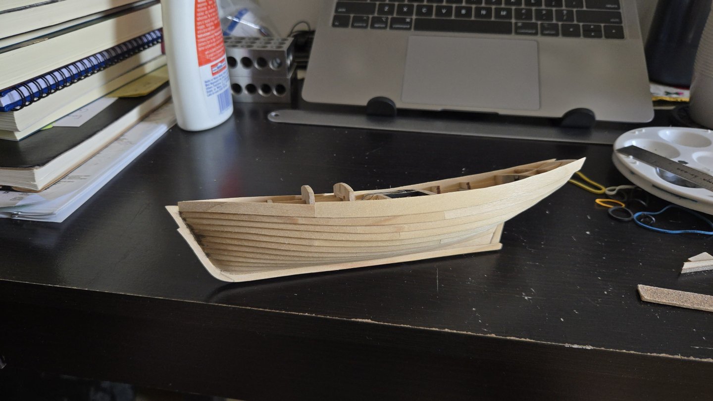
Thanks, all! @Kenchington, I'm planning on trimming the pump handle shorter, but for now I'm leaving it long--it's a tiny piece and is harder to lose if it's slightly bigger. At long last, the planking is finished! I have to admit that it took way longer than I had thought it would, but I'm pleased with how it turned out and glad I decided to give lapstrake planking a shot. I found that I couldn't really clamp the sheer strake for gluing: there was no overhanging bulkhead to clamp to, and as the plank ends above the bulkhead, rubber bands exerted too much leverage and tilted the plank. I had to go by hand instead, gluing in sections. It took a while, but I was able to listen to music or watch movies while holding it in place. The sheer strake was deliberately oversized on the upper edge. I then dry fit the deck and marked the proper height with a pencil. Then, I shaved and sanded the sheer strake down, leaving just a little of the pencil line. It can be sanded smooth to the final fit once the subdeck is in place. (Below, there's still a bit to trim). Once trimmed, it looked quite nice. The photo below highlights a few points where I need to smooth off some lower plank edges, which I will probably do after adding some shellac--some of the basswood was a bit stringy and could be usefully sealed. I then removed the bulkhead tabs from the cockpit and began finishing the floor planking. The hull shell around the cockpit was quite sturdy. I also bent some 1/32-inch thick stringers to represent the frames. I found that clamping as below indented them a bit, but for actual gluing, I rounded off the edges of a bit of scrap to press the frames into shape and it worked better. Initially I planned on doing 3 frames in the space, although I upped it to 4 before gluing. Below, the cockpit fully planked, four frames added per side, and the tops trimmed. They're still a little dented, but they'll be barely visible below/behind the deck, coaming, and benches, so I'm not too worried. Same with one of the frames being slightly misaligned due to sliding a bit while clamping. I also trimmed and sanded the transom area, and added some wood filler to smooth the planking ends. You can also see that I filled in the large square gap around the rudder shaft hole, and later drilled it out. The lapstrake planking is a neat effect, I have to say. And the current state of the build:


-
Very interesting work on what's in a name, thank you for sharing! I have to admit that I've often been confounded by the cutter vs sloop distinction. If I understand usual present-day usage, a Friendship Sloop can technically be called a cutter (though I've never seen it referred to as such) because of the two headsails? Not to mention the complexity of trying to disentangle what writers past and present mean by different terms--sometimes it's hard to tell whether they're using the term used by the boat operators themselves, or applying their own label. Sometimes it's obvious, though. Amusingly, one traveler to Lake Chapala, Mexico, around 1900 referred to the local flat-bottomed boats as "smacks," apparently solely because they were used for fishing. (While another writer called them "schooners" despite them all being single-masted... thank goodness I could rely on photos instead of written descriptions for my build!) One question: so would the Muscongus Bay Sloop/Boat/Smack have had hopes drilled in the planking for the live wells? I'd imagine so, but I haven't seen this in any plans or images.
-
Excellent work! The little details really make it something special.
-
Amazing work! The view from inside the hull is really incredible.
-
Great work! What did you think of the kit overall?
- 45 replies
-
- 2
-

-

-
- Fischkutter
- Laser Creation World
- (and 1 more)
-
Novice builder and question re: Amati felucca
JacquesCousteau replied to jrbm's topic in New member Introductions
Welcome, nice start on your build! "Felucca" is a pretty wide-ranging category, but I also am not aware of any with a transom bow like that. The box says "Felucca 1887," do the instructions or box give any indication of what specific sort of felucca it's supposed to represent? Unfortunately many kits are inaccurate in various aspects. Nice-looking model, though, seems like a good introduction to planked hulls. -
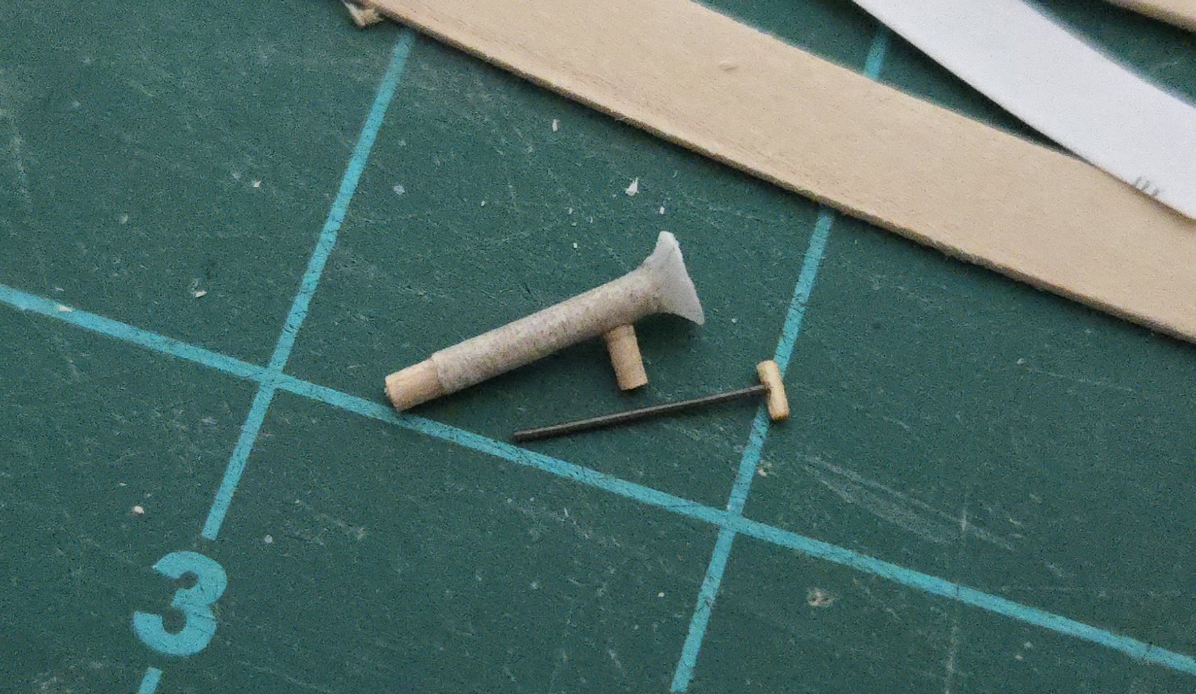
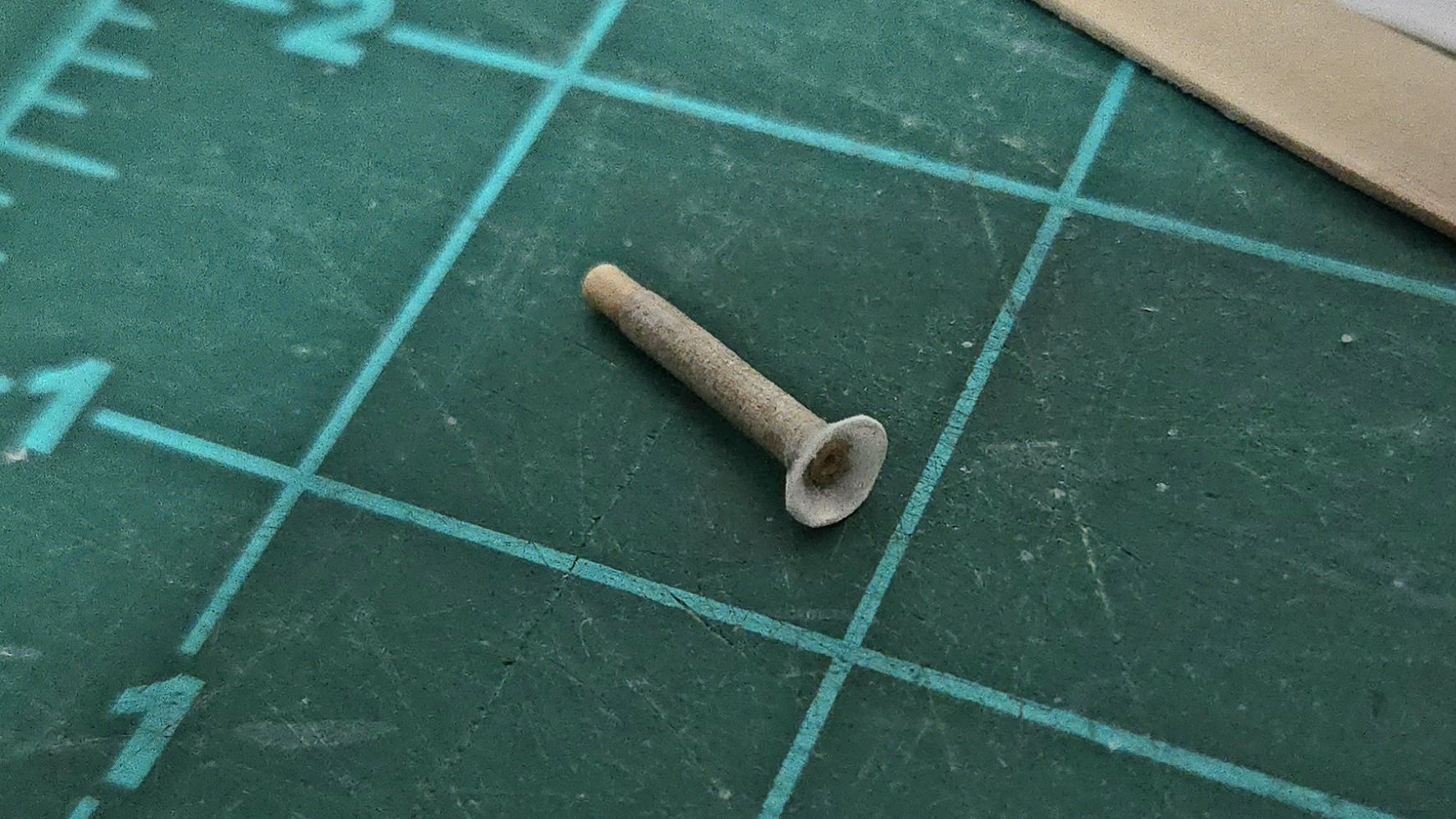
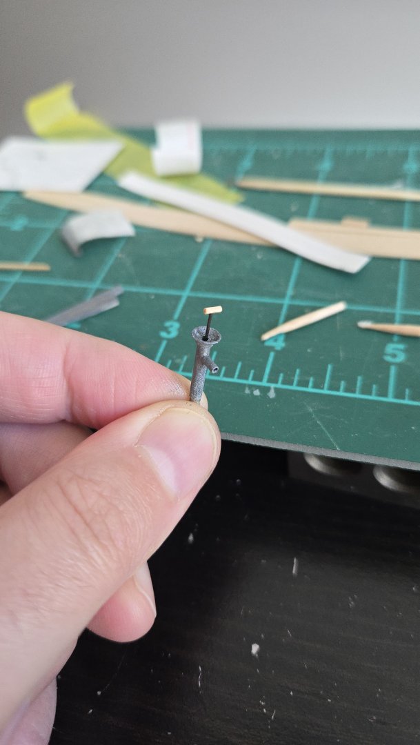
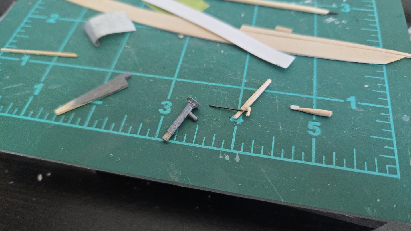
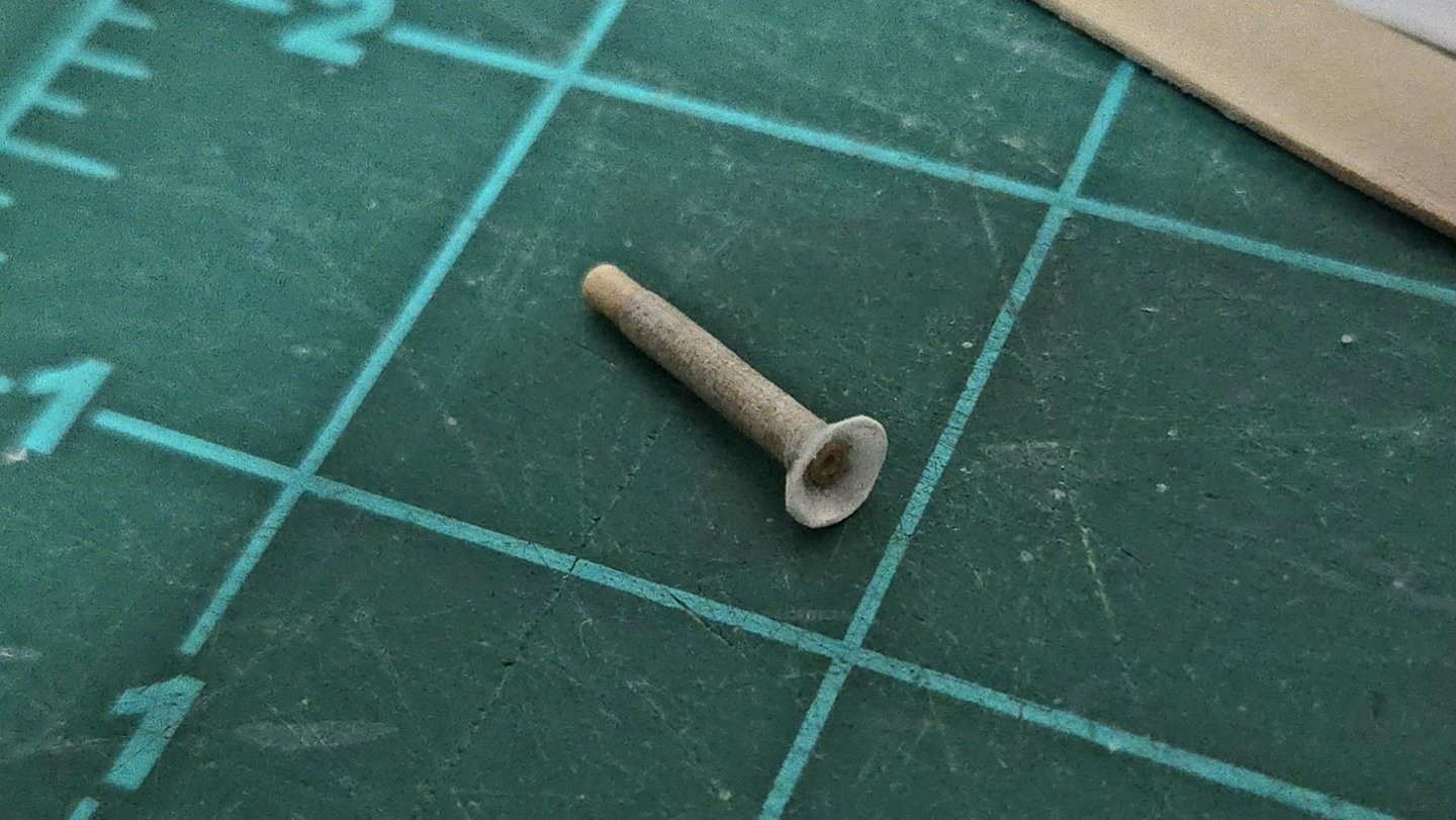
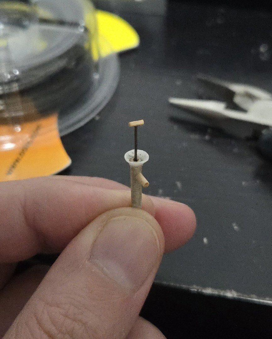
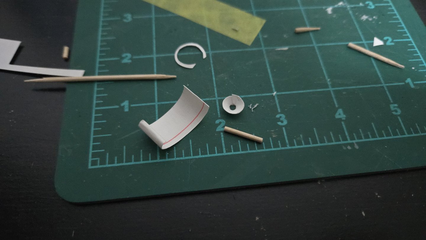
The sheer strake is a little more complex than I had thought. I initially tried to do it as one plank, but it was hard to get the curve just right. One issue with marking lapstrake planks is that the plane of the tape needs to follow the plane of the strake, which is propped between where it touches the frame/bulkhead and the edge of the lower strake. There isn't much contact area, and it's easy to accidentally stick it on the plane of the strake below, which slightly distorts the curves compared with the necessary plank shape. To get around this, I'm splitting the strake in two parts. Meanwhile, I've been doing so much planking lately (and am about to start planking the Bateau de Lanvéoc too) that I wanted to take a break and do something different. I thought about things some more, and decided to go for the galvanized, possibly removeable pump, as I thought its compact size would be well-suited for the narrow confines of the cockpit. Initially I was going to use a thin dowel, but checking it, it still looked a bit thick. Instead, I chose to use a toothpick, which I then built up slightly by wrapping paper around it (which also covered the unevenness of the toothpick surface). I tried with card first, but it didn't roll very well and seemed thick, so I ended up going with thin paper. I did use the card, though, for the funnel shape at the top. I then coated everything in super glue, and tried to sand out any unevenness/overlaps once it dried. I also glued on the funnel and cut it down to a reasonable size. I then drilled out the hollow shaft from the top. The outflow tube was also made from a portion of toothpick, sanded down and with an opening drilled out, after some failed attempts with paper. The handle is just a bit of thin stained basswood glued to a wire. I was actually pretty pleased with how it turned out, although I'll need to cut the wire shorter. To get a galvanized look, I painted it with Vallejo "metallic gray" (or at least that's the translation of the Spanish name, I don't know if it's gunmetal or something) and then a wash of white over it. I then drilled out a hole in the cockpit floorboards and temporarily added it (and the portions of the benches I've made so far). I will probably add the pump body once I build the cockpit, but will leave off the handle until the end of the build, as it would be very easy to snag. Thanks, all, for your helpful comments and suggestions on the bilge pump!


-
Amazing work! What a beautiful hull form.
-
Very cool project!
-
Very nice work, the window is a great touch of realism. I wonder if a thin sliver of basswood could serve as trim to cover the gaps you mentioned?
-
@Stubby and @Kenchington, it will definitely be a bit of a challenge. Scribing the deck could work, but I haven't been very satisfied with my previous attempts at scribing. I'm planning on using 1/32-inch thick material for the deck planking. I'm not too worried about slightly raising the hull by an inch (at full scale), as there are a lot of hull forms for Muscongus sloops--notably, the hull of the Ranger seems a bit deeper than the Chapelle drawing the kit is based on. If I need to, I think I can also slightly raise the cabin sides and coaming. That said, I'm going to test fit first and see of it looks bad. If I does, I can use my mini plane to thin the deck planking down to 1/64-inch or so. It will certainly be an experiment!
-
Thanks, @Rick310, @Paul Le Wol, @Keith Black, @Kenchington, @wefalck, @Stubby, and all those who have checked in with likes and page views! @Kenchington and @wefalck, I agree that evidence seems to show that the mast was round where it left the deck. I hadn't considered that a round opening would be less prone to leaking than a square one, but it makes sense. Interestingly, the lancha chilota (my last build) did have a squared off mast at the deck, so I approached this build with that in mind. Unfortunately I already squared the mast step and accidentally made it a bit large, so I'll need to figure out how to build it back up a little. Which is tricky with the hull already planked in. @Stubby, I decided to leave the deck off so I could remove the visible bulkheads from the cockpit and add frames after planking. This left the bulkheads a little flimsy for fairing, so I added a bunch of internal supports. I'll be planking over the kit-supplied deck, so it's not the end of the world if the hull planking doesn't fully join up exactly with the side of the deck. I had to take into account the thickness of the deck while setting up my planking runs and the width of the sheer strake. Even taking that into account, I'll be making the sheer plank a bit excessively high and sanding it down once the deck is in place.
-
Very nice work, I like how you've handled the cabin! What program did you use to come up with the paint scheme? Is it just ms paint? I don't have a good sense of color, so I would love to be able to check possible color schemes before painting.
-
Thanks, @Stubby, I enjoy research about as much as building! And thanks, @Keith Black, for the pump examples! More work on planking. I've been able to get a little better at lining up the top line of the plank joints. One issue I've had is that, due to the different plank widths and strake lines of my model compared to the kit design, I haven't been able to use much of the kit-designed prespiled planks. It feels like a real waste--it's a great feature of the kit, but it doesn't really work if you go with lapstrake planking. So I was happy that, for the next strake, which is the one below the sheer strake, I realized that I could make it from the kit-supplied sheer strake, which for whatever reason was slightly too short to work as the sheer strake on mine. (Maybe my transom extends a little farther aft than it should? Or I screwed up something in the scan and laser cut process?) It's a lot wider than the normal planks, so I could spile from it, as seen below. At this point, there's very little bulkhead to clamp to, so I've had to be a bit creative with rubber bands. I now just have the sheer strake left to add. I feel like, for a vessel of this size, it would probably be best to make it from a single piece, although I'm not looking forward to the complex gluing process that will entail. I'm pleased with the lapstrake planking so far. Before painting, I think I'll add a coat of shellac to help seal and strengthen the wood so I can touch up any stringy/ragged visible edges. Elsewhere, I've begun work on the rudder and mast. The mast is made from two layers of basswood, which mitigates against the relative weakness of basswood as a mast. Before I round off the mast, I need to decide whether it should be round all the way through, or squared-off at the deck. My initial thought was that, on an unstayed mast, a square cross section low down would keep it from spinning around. I began cutting the mast step partners square, but accidentally made them bigger than they should be, so it doesn't quite fit like it should and I'll need to take care when I step the mast. Moreover, it looks like Chapelle's plan shows a round mast at the deck, so maybe I should just round it all. I'm also trying to figure out whether to use brass rod or wood for the rudder shaft.


-
Very cool project, looking forward to following along!
-
The issue is also discussed in Bryan Woods' build log:
- 29 replies
-
- 2
-
-
- Lowell Grand Banks Dory
- Model Shipways
- (and 1 more)
-
I couldn't remember how I did it on mine, so went looking. I don't discuss it in my build log, but there's a photo in the post linked below showing what looks like your second/middle option.
- 29 replies
-
- 2
-
-
- Lowell Grand Banks Dory
- Model Shipways
- (and 1 more)