


Greg Davis
-
Posts
350 -
Joined
-
Last visited
Content Type
Profiles
Forums
Gallery
Events
Posts posted by Greg Davis
-
-
How true - 2 years ago I build the ModelExpo kit of Emma C. Berry and I was able to access a good deal of information about the vessel. Books on her history and reconstruction were available and there were pictures from different periods of her life. In many ways this made decisions on how to represent the the ship more difficult. A model can only represent a snapshot, so its hard to pick one if you have information spanning decades but not a great deal at any specific timepoint. I think that's the problem here with Le Pourquoi-Pas? - the available (undated) pictures of a ship that lasted nearly 40 years show some of the potentially many snapshots and we only get to make one in static model form.
- clearway and Keith Black
-
 2
2
-
In Charcot's journal of the polar expedition, 1908 - 1910, there is a picture of the ship in which you can make out that the bridge is like that in the Constructo kit. So my guess is that the basic bridge with canvas wind block was original; then perhaps, it was decided that it was too cold so the small enclosures were added; and finally, the structure was cut down / simplified before the Pourquoi-Pas? was lost in 1936.
-
I saw a couple of pictures online that seem to indicate that the bridge / observation area changed a number of times thru her history. In the model the observation area is open from side to side. In this picture enclosures have been fashioned on the sides.
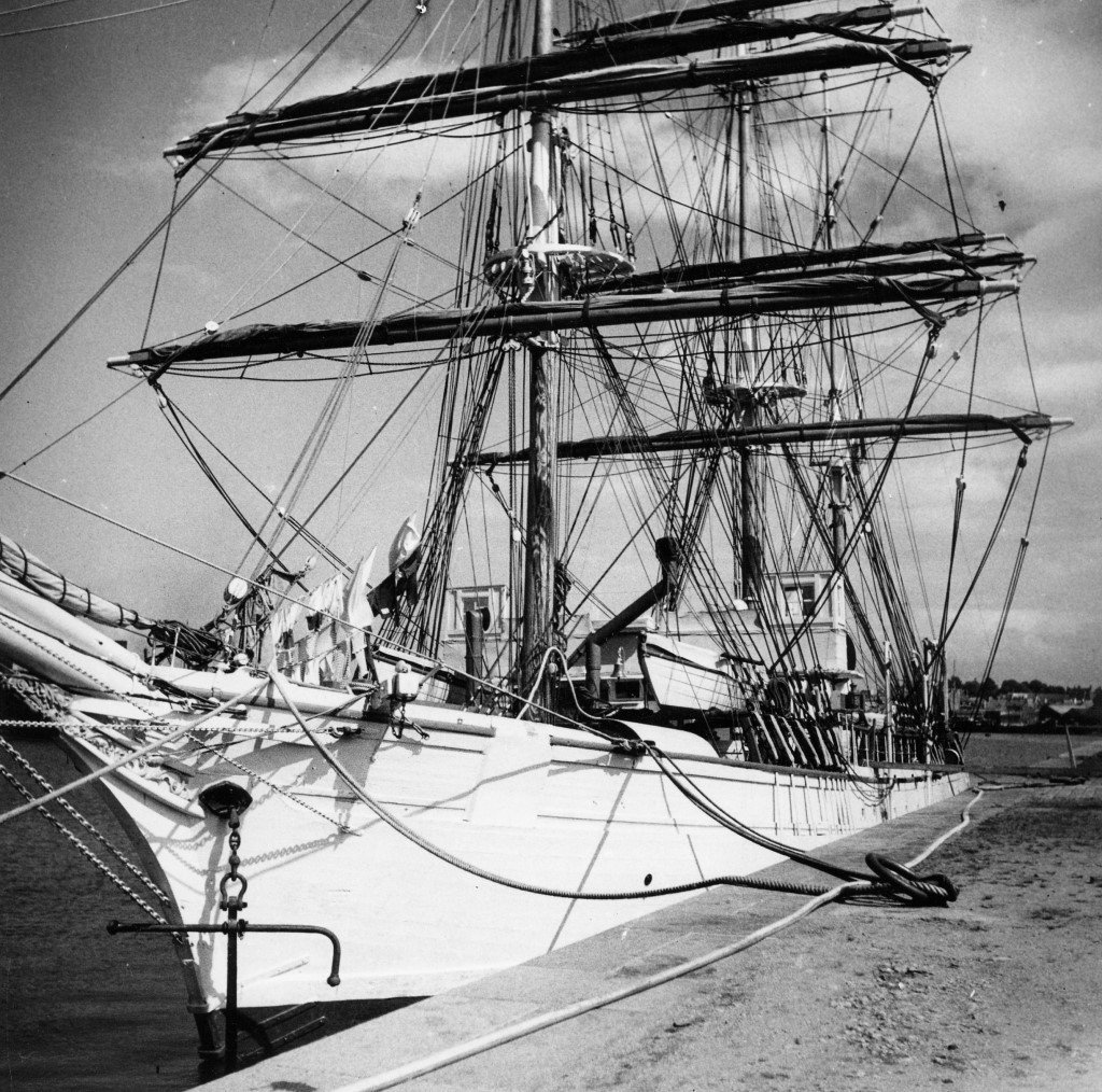
Ans in this picture, it looks like the observation region has been removed.
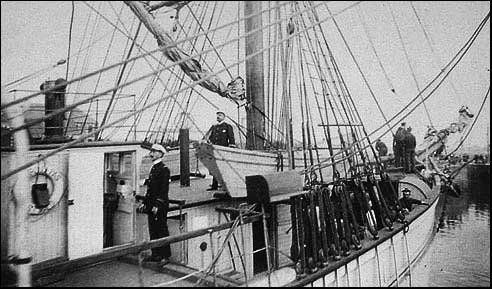
Unfortunately, I don't have any idea as to the timing of these images.
-
Just read your entire Terror log - simply spectacular!!
- clearway, Mr Whippy and Keith Black
-
2
-
 1
1
-
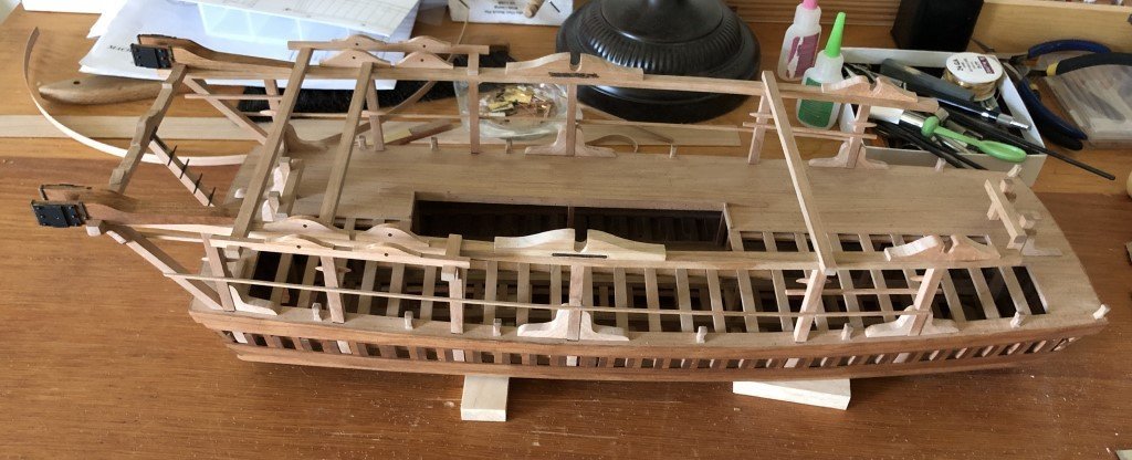
Starting to attach subassemblies to the deck. The three large deck structures that were made earlier are cemented in place. The 4 remaining ventilators have been attached to the deck. Anchor davits, bitts, etc. are being added.
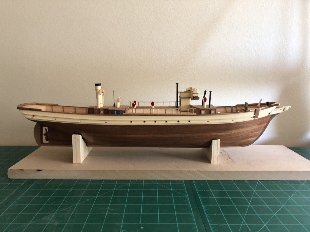
The deck of this vessel is pretty 'busy' so for a while little structures / details will be constructed and added to the model.
- druxey, Keith Black, Auger and 1 other
-
4
-
On 5/22/2023 at 2:28 AM, G. Delacroix said:
Hello,
Congratulations on obtaining these awards, they demonstrate the quality of your model's execution as well as the application and value of your work.
For your next model, I take the liberty of recommending L'Invention, which will be much simpler than L'Egyptienne. This beautiful frigate is truly a big ship with all the complexity of the work of carpentry, artillery and decoration that this implies.The Invention is structurally simpler without being easy but, to my taste, it has the advantage of novelty both in the world of model making and in the innovations it brings for the time of its construction. Moreover, it is an opening towards the clippers which will succeed it fifty years later.
Whatever you decide, I have no doubt that your project will succeed.And thank you for the citation and the compliments.
GD
Mr. Delacroix:
Thank you for your input; I've spent more time exploring plan sets for both of these ships, and have now decided that in the near future I will open a build log for L'Invention. I am also fairly sure that the model will be made primarily with pear wood. As with the dredger, I will do my best to make an honest and high quality representation of your work.
Greg
- bruce d, druxey, Keith Black and 3 others
-
6
-
I got back to working on this ship last evening - hopefully there will be regular progress until completion.
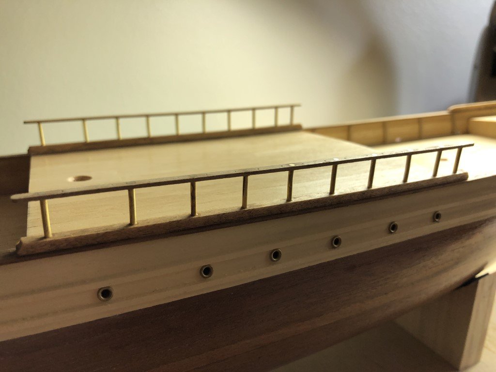
First addition this week was a set of handrails made from 1mm x 3mm material. There are a lot of holes in each - 10 for stations and 25 for belaying pins. I cut the handrails to length and marked the location of the holes, then I drilled 70 0.5mm pilot holes. The rails where clamped to their locations over the deck and the station holes where enlarged / drilled through the handrails into the vessel - first with a 1mm drill and then enlarged to allow for the 1.5mm brass wire the stations are made of. Everything was glued up with CA, the excess brass snipped off and then filed flush to the handrails.
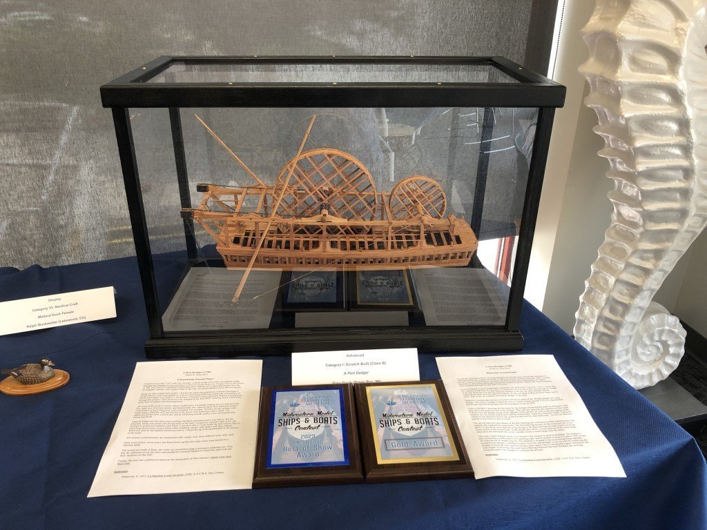
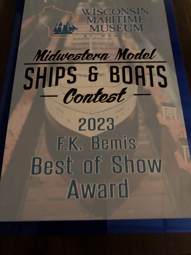
Also, my dredger project was completed (hours) before the 46th Annual Midwestern Model Ships and Boats Contest held at the Wisconsin Maritime Museum. Here is what it looks like completed and mounted.
When the awards dinner came around Saturday evening, I was hoping that my work would at least have earned a silver award - so I was extremely pleased when the dredge and my name was called for a gold award. But the evening was not over, and still unbelievable to me - the judges had determined that this model would be awarded Best of Show!
-
I do have a question -
Do any of you know of documentation / plans any other interesting service boats (short of anchor hoys)?
I found this dredger to be fascinating, and I think that many should be indebted to G. Delacroix for bringing his study to us, but now I am interested in whether or not there is a logical / related follow up project!
If not, then I may make a seemingly irrational decision to dive into either L'Egyptienne or L'Invention - both that interest me greatly
") .
.
- GrandpaPhil, mtaylor, druxey and 1 other
-
4
-
Very sorry about the lack of updates. During the past two weeks I have been doing a lot of 'little things' - nothing that really seemed worth reporting, yet all together the job is done!
I did order and receive a follower rest for my lathe and this accessory helped me fashion the second scoop arm in approximately one-third the time the first took. So I feel the follower was definitely worth the money. When ordering the follower, I convinced myself that a rotary table would be a great addition to obtain. That's a pricey one, but it really made slotting the davit (chain) rollers a pleasant task. Each roller, that is about 13mm in diameter, required 20 parallel slots for metal reinforcing strips. The rotary table let, together with a slitting saw, let me make the slots an even 18 degrees apart all around the roller.
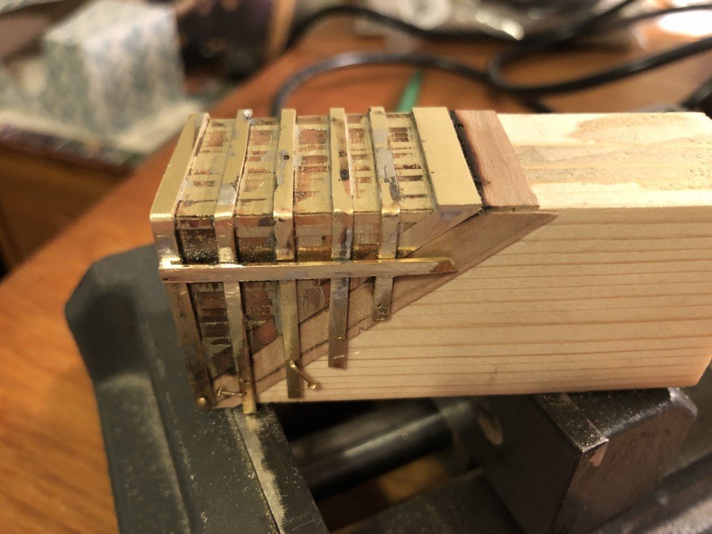
Work on the scoops continued. Here is a picture of the port side scoop before drilling holes for fasteners (which require a whole slew of drill bits as they quickly dulled)
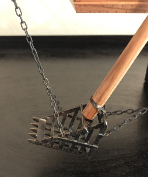
To keep with the 'open' starboard presentation, I decided present the starboard scoop in a skeletal fashion. Here is a picture of that scoop that was taken after connecting to the vessel:
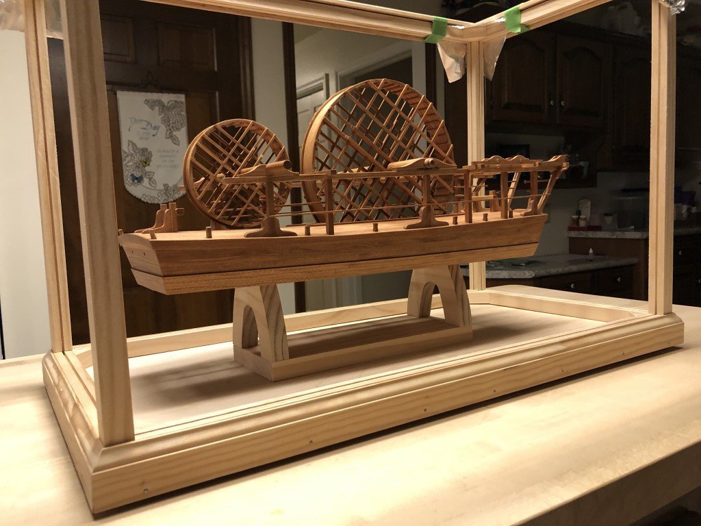
As I was approaching the final setup it was time to build a display case. Here the case is approaching completion and I am adjusting the location of the dredger inside the confines.
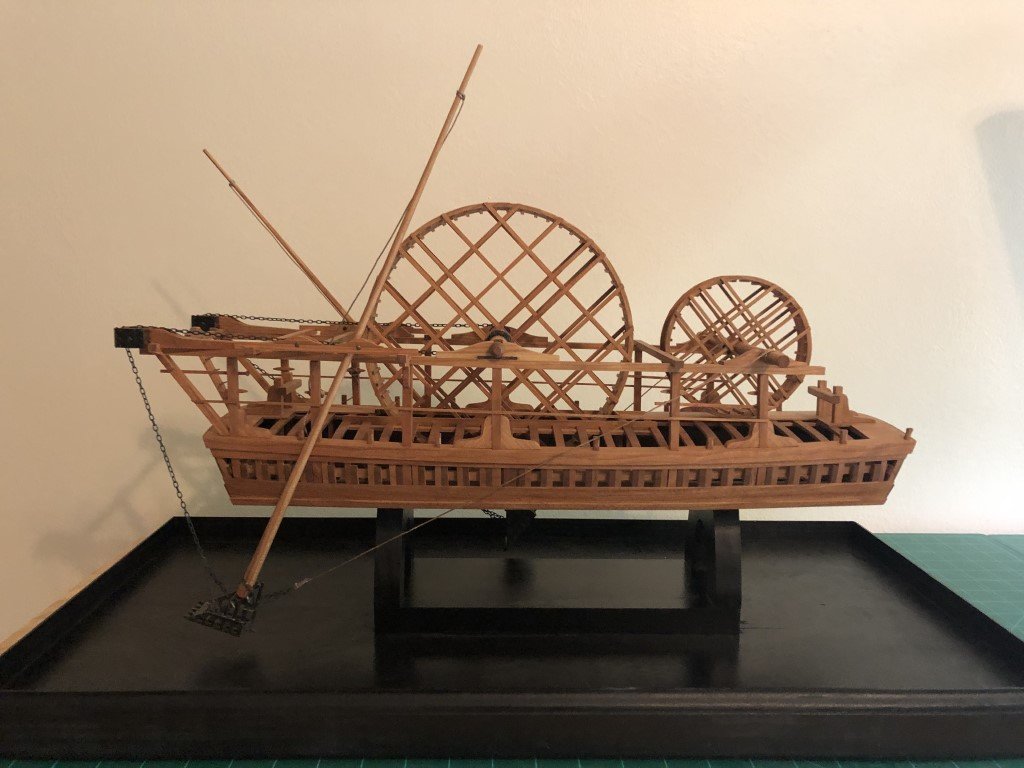
Once the case was painted black, the hull was mounted via bolts going up thru the arches into the nuts imbedded in the keel. Then the scoops were setup with their chains and return ropes. Finally, the scoop brails were added. Here is the result:

That picture was taken Thursday evening. Friday morning and into the early afternoon, the glass was added to the case. The finished product was loaded up into my truck and driven down to the 46th Annual Midwestern Model Ships and Boats Contest held at the Wisconsin Maritime Museum. At this contest all entries are placed in group types (kit, scratch, etc.) as well as by experience (novice, intermediate, advanced). Models are then judged individually against a rubric. Based on the number of points received, each model is then placed in an award category (bronze, silver, gold). If a modeler receives a gold in the novice category, next time they must advance a class. Similarly if a gold is received in the intermediate class, then in future years entries need to be placed in the advanced level. Last year I had received gold in the intermediate category with a kit build model of the fishing sloop Emma C. Berry. So although the dredger was to be my first scratch built entry, Kurt Van Dahm kindly directed my entry to the advanced level.
Needless to say, when the awards dinner came around last evening, I was hoping that my work would at least have earned a silver award - so I was extremely pleased when the dredge and my name was called for a gold award. But the evening was not over, and still unbelievable to me - the judges had determined that this model would be awarded Best of Show!!! Kurt suggested that I let you know last evening and I would have, but for some reason I was not able to access the MSW website last evening (or this morning).
I cannot thank you enough for the kind words and encouragement that all of you have provided me over the past 10 months. The journey has been supremely rewarding. I'm going to consider this model 'done' for now and am starting to think about my next building adventure. Again thank you and I hope that you have found some enjoyment following this build.
-
The last couple of days have been dedicated to the scoop arms and the scoops themselves.
I've formed one of the scoop arms. It has an interesting contour, the lower part changing shape in a convex nature, whereas the upper part is more conical. The scoop arms are near 40cm long, 8mm diameter at the base, and tapering to 3mm at the top. It took me nearly two days to turn the first scoop arm. I found it difficult due to do the turning because of the large length to diameter ratio. I have a steady rest rest for my lathe but it seemed to offer just limited help. I've ordered a follower rest in hopes that this accessory will help in forming the second scoop arm.
I believe that I have cut enough brass stock for the sides of the scoops and also stock for the straps. I have started to assemble the first scoop and have made the first couple of solder joints. I have essentially no background in successful soldering so this is really a learn as you go part of the build! I am following the basic scoop assembly order and method that is shown in the Ancre monograph.
-
I also completed most of the work for the scoop guides and their associated axles (with washers). The hourglass shaped guides still need to be oiled and the axles need to be shorted to their final length. But all of the turning is done and the axles have already been drilled for fasteners.
This work did get slowed down when the drive belt on my lathe decided it had reached its life expectancy. While I have backup belts for my Byrnes table saw and thickness sander; I found that I had committed an oversight by not having backup belts for my Sherline lathe and mill. The drive belt failure led me to nearly two days of belt searching. After finding out what type of belt it was, I thought this can't be to hard to obtain for less than Sherline charges! They want $9.95 for a belt and for 3-5 day shipping another $10. So, I found the exact belts MB330's on Amazon - 2 for $7.99 with free delivery. At first they were suppose to arrive by 2 May; now maybe by 8 May - who knows as they are being shipped from China. So I ordered a generic 13 in belt for a few dollars and it came a day later. Not a great fit for the lathe, but it is functional with the lathe motor pushed as far from the drive pully as possible. It worked (big axle doubler) but will be replaced with a MB330 when one arrives - maybe tomorrow; yep I sucked up the $10 Sheline delivery fee for an item that weighs an ounce or two.
-
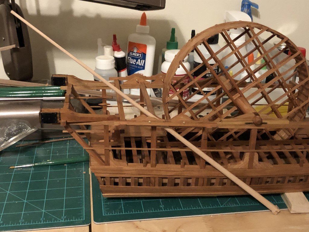
Its been a few days and a few tasks have been completed.
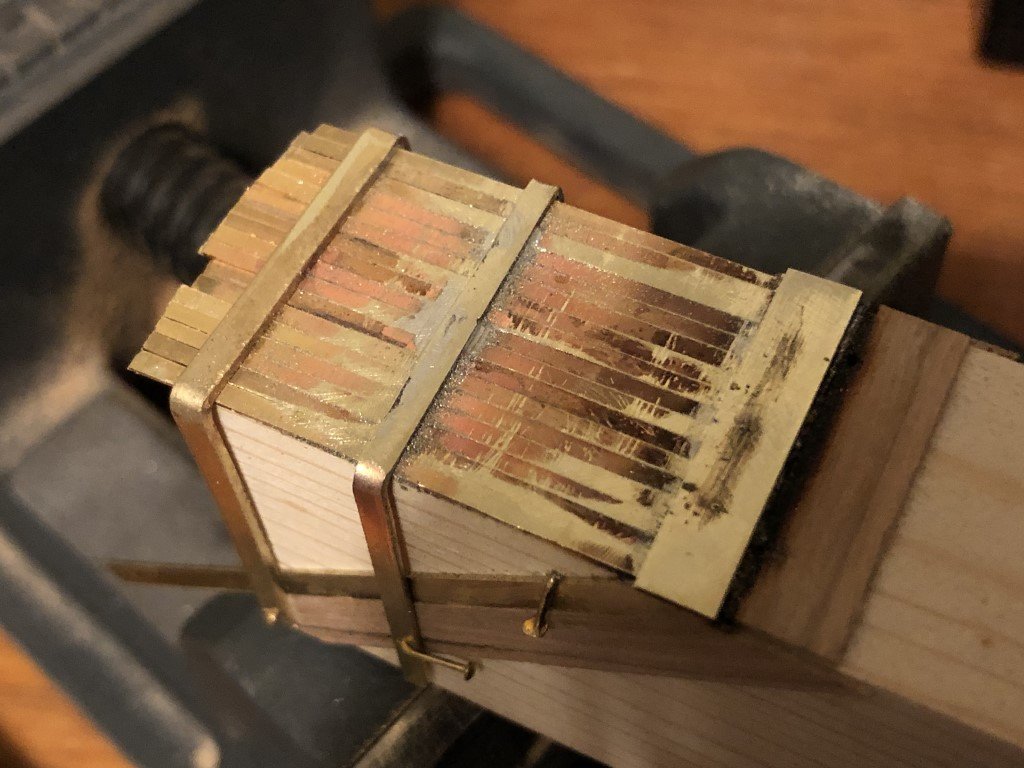
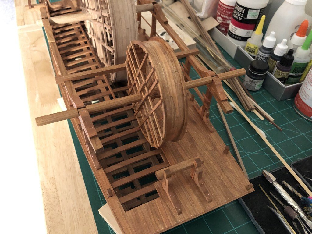
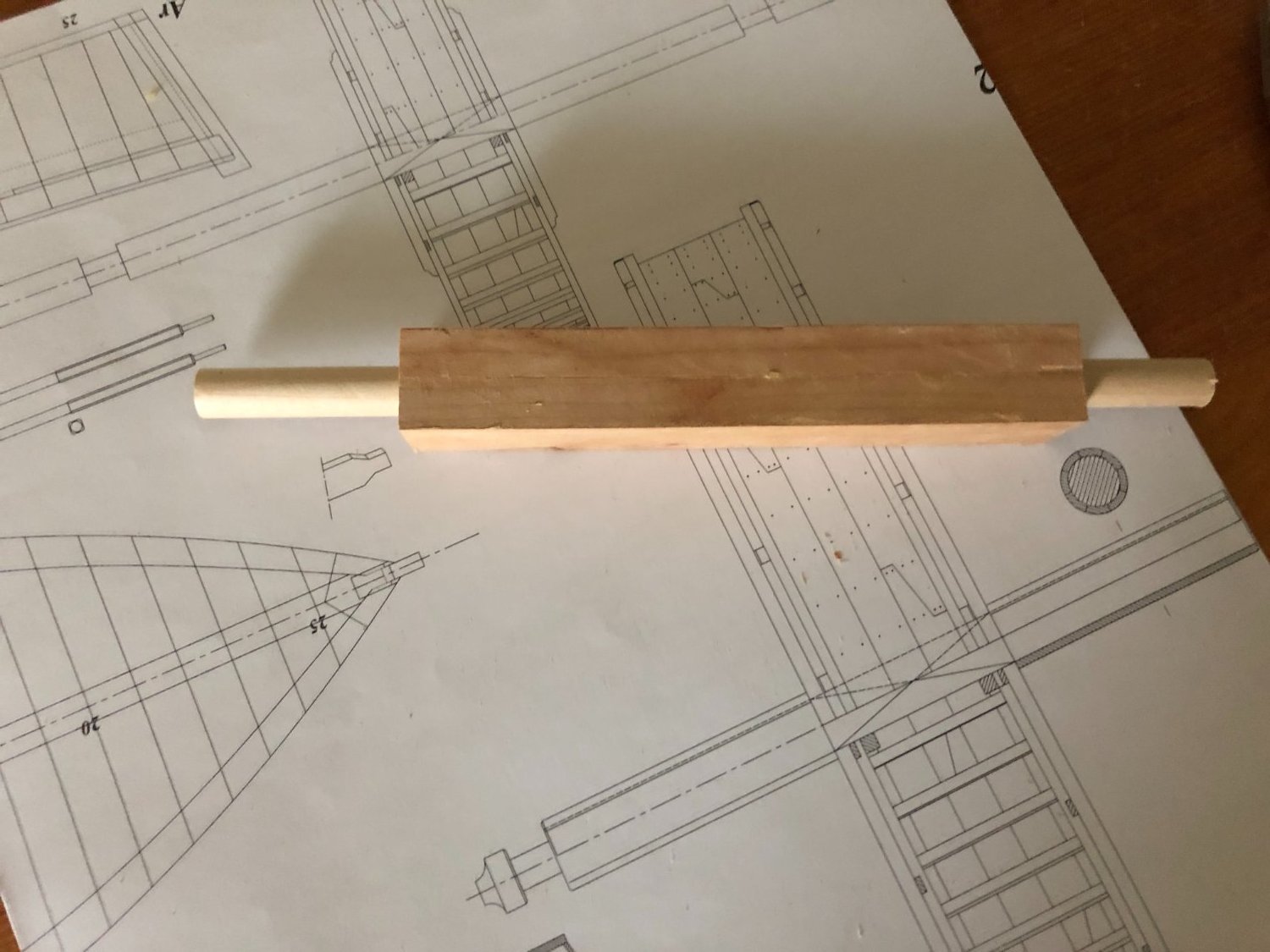
I just finished the big wheel structure; so all of the planking fasteners are in place, and after a bit of thought and work the axle doubling is done.
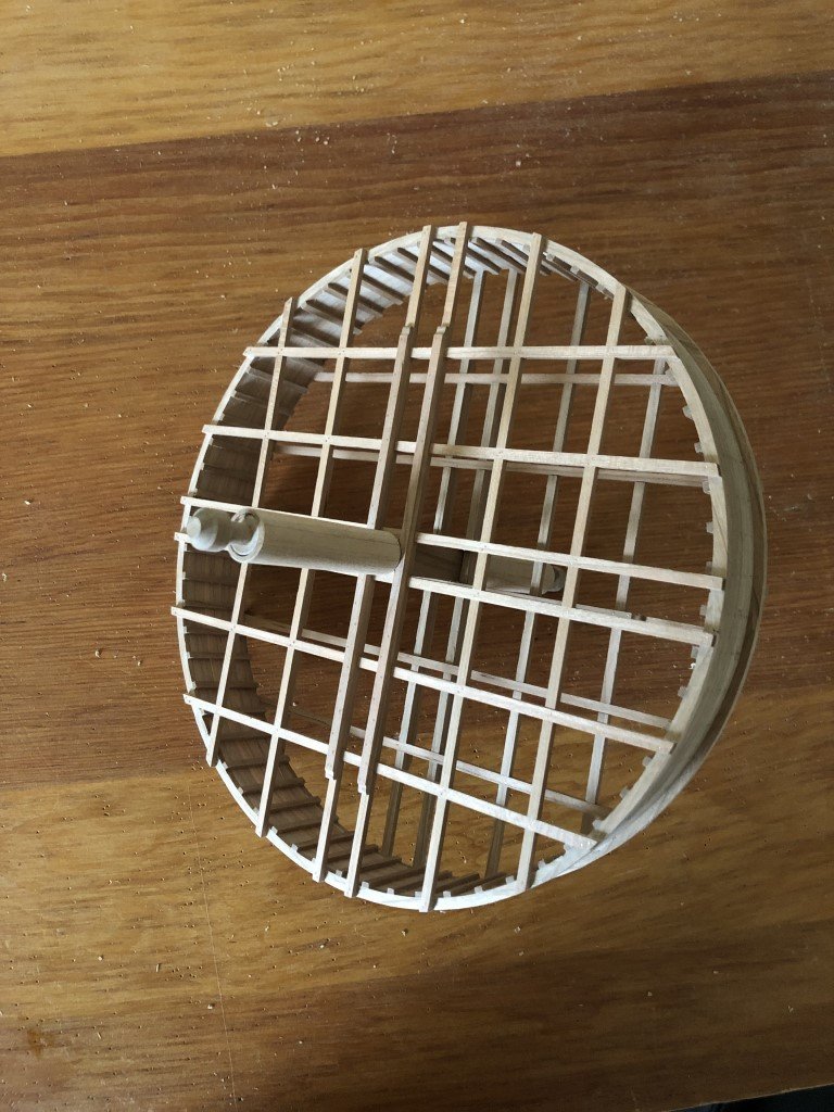
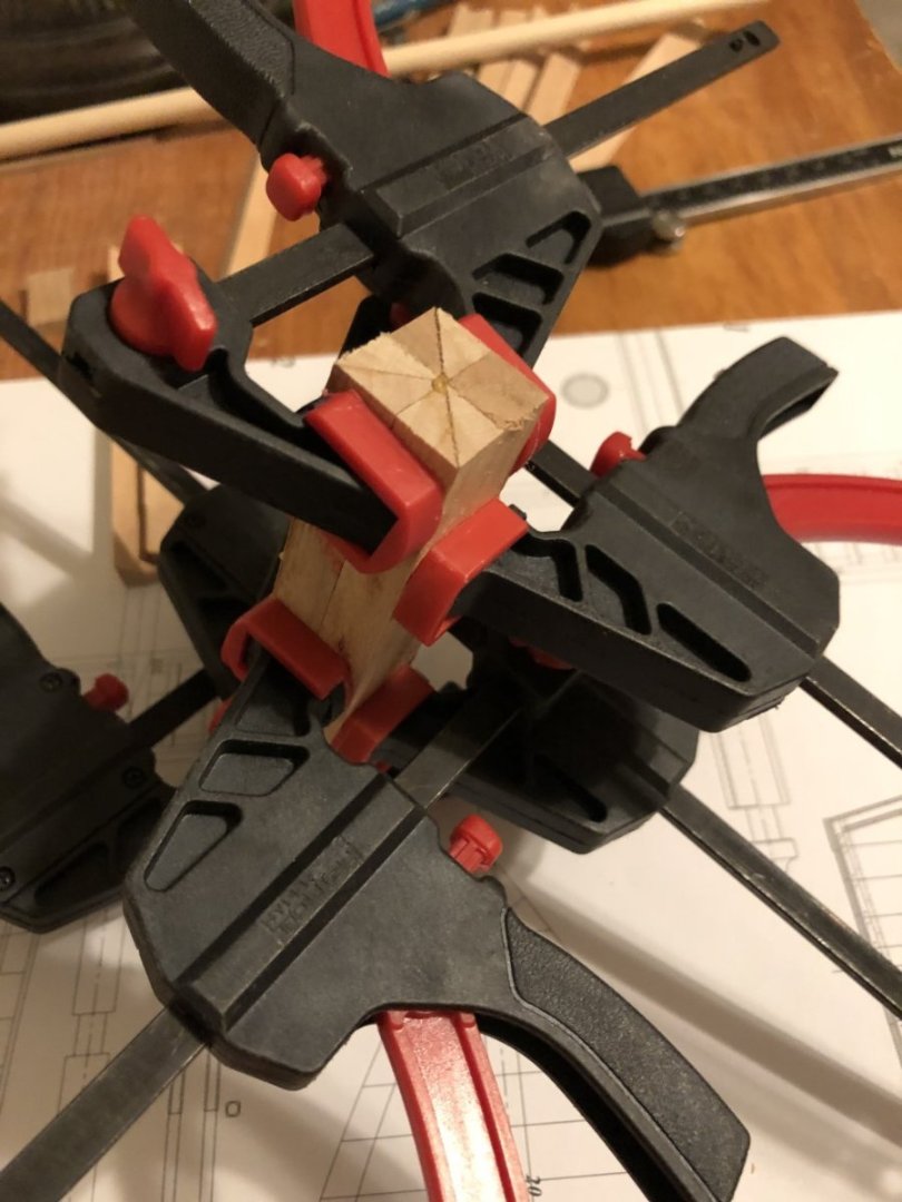
At first I was not sure how I was going to make the axle doubling - eight planks evenly spaced about the axle. Then I recalled how I had previously seen capstans and barrels made from built up blanks. This led me to cutting a bunch of wood to a 45 degree angle and then using 8 pieces a blank was produced.
Next I drilled out the middle of the blank in a series of steps, the last being with a 3/8" bit - this was the closest I had (but smaller) to the axle diameter. I then passed a 3/8" dowel thru the hole before using a lathe to fashion the outside diameter of the doubling.
Once the lathe work was done, two lengths of the resulting cylinder were parted off and removed from the dowel. To finish, I used a tapered dowel covered in sandpaper, spun on a hand held drill, to open the cylinder's hole just enough to slip the doubling onto the axle. A spot of glue and job done!
Now it is time to oil the structure and place it onto the superstructure.
-
-
Today I finished the small wheel; i.e., got all of the fasteners in, attached the wheel to its axle, and oiled the assembly.
I have also completed the planking on the big wheel. It is now ready for fasteners and finishing.
- GrandpaPhil, Ainars, Keith Black and 4 others
-
6
-
 1
1
-
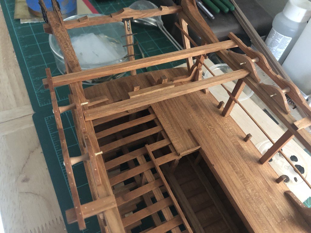
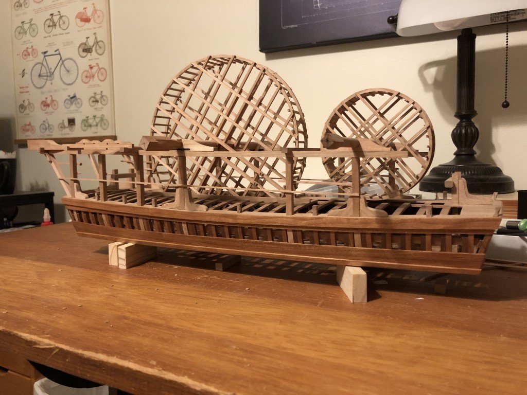
Since my last post, I have added all of the superstructure fasteners and metalwork. Here is the last picture I took before oiling the deck and superstructure:
Today I spent nearly 4 hours swabbing linseed oil onto the deck and upper works. I think it is looking pretty nice, and am really looking forward to seeing it with wheels and scoops.
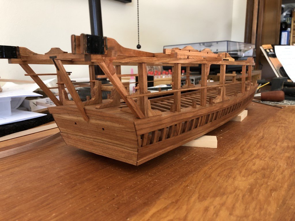
In a few days, when completely dry, I can think about adding 6 ring bolts to the deck. I believe the main purpose of these ring bolts was to attach ropes with hooks that could then secure the wheels during transport / anytime one would not want them free to turn.
Now my attention will turn to finishing the wheels. Simultaneously, I will start working on the scoop mechanisms. I guess it is also time to select a mounting / display mode for the vessel.
-
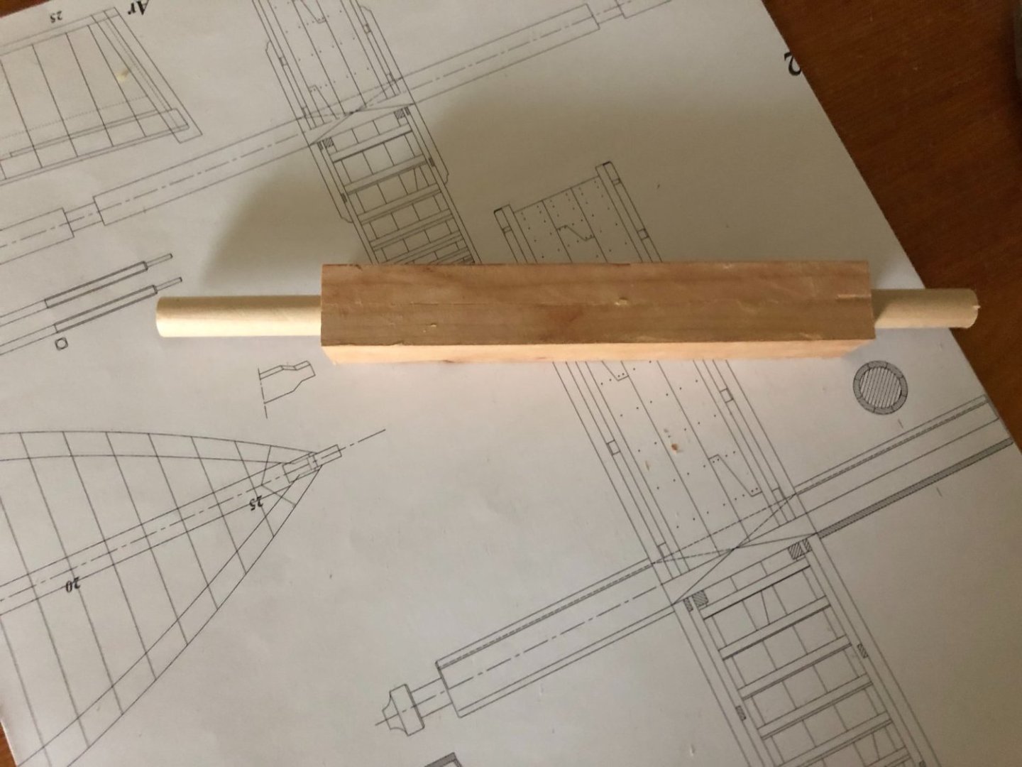
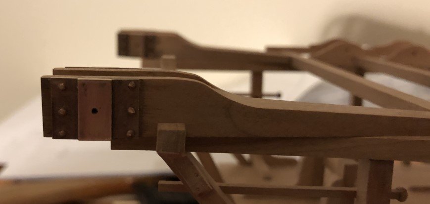
Over the past few days I did make a new set of axles. These will be keepers!
Later the big wheel axle will get some doublings to help support the scoop chains.
Above you can also see that I am adding the fasteners to the scoop guide components. I've been doing a lot of fasteners lately - guard rails, cleats, foot boards, ... Still quite a few to go on the superstructure, but progress is being made.
Here is the new small wheel axle.
I've been doing other odds and ends as well; for example all of the small wheel steps have been made flush with the rims and some metal work has been done on the davits.
- Charter33, G. Delacroix, GrandpaPhil and 7 others
-
8
-
2
-
-
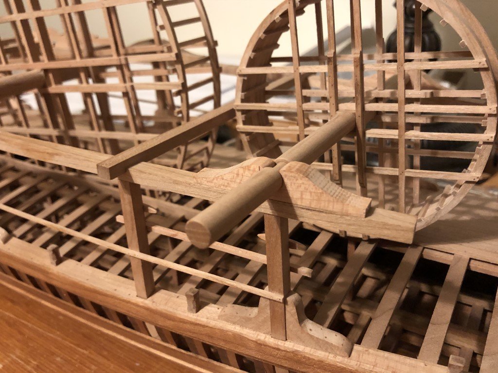
The wheel bearings are complete and firmly attached. Cleats are in place as well - not too easy to see, but they are on the inside of pillars 1,2, 5, and 6.
The two wheel axles in these pics are now classified as 'practice pieces' - they were fails, better ones will be made! However, they are being used to check wheel alignment, etc. Looks like everything is going to be were it belongs.
- James G, G. Delacroix, GrandpaPhil and 11 others
-
10
-
4
-
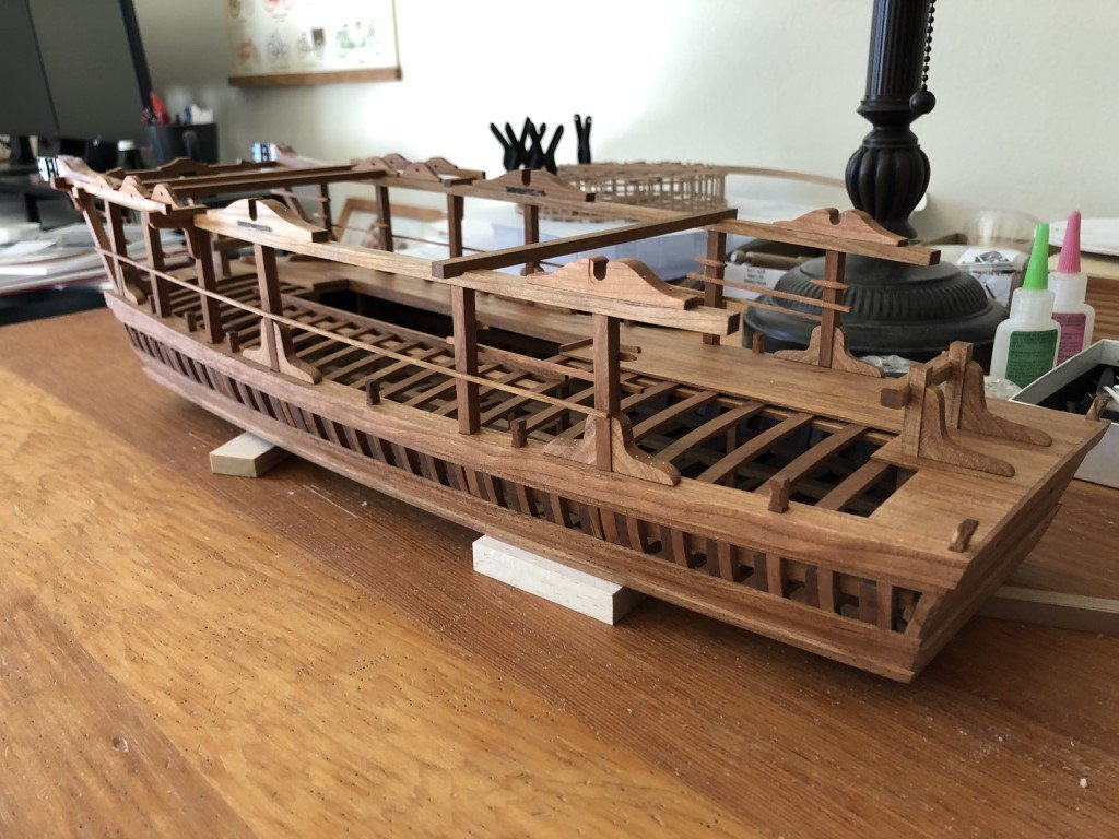
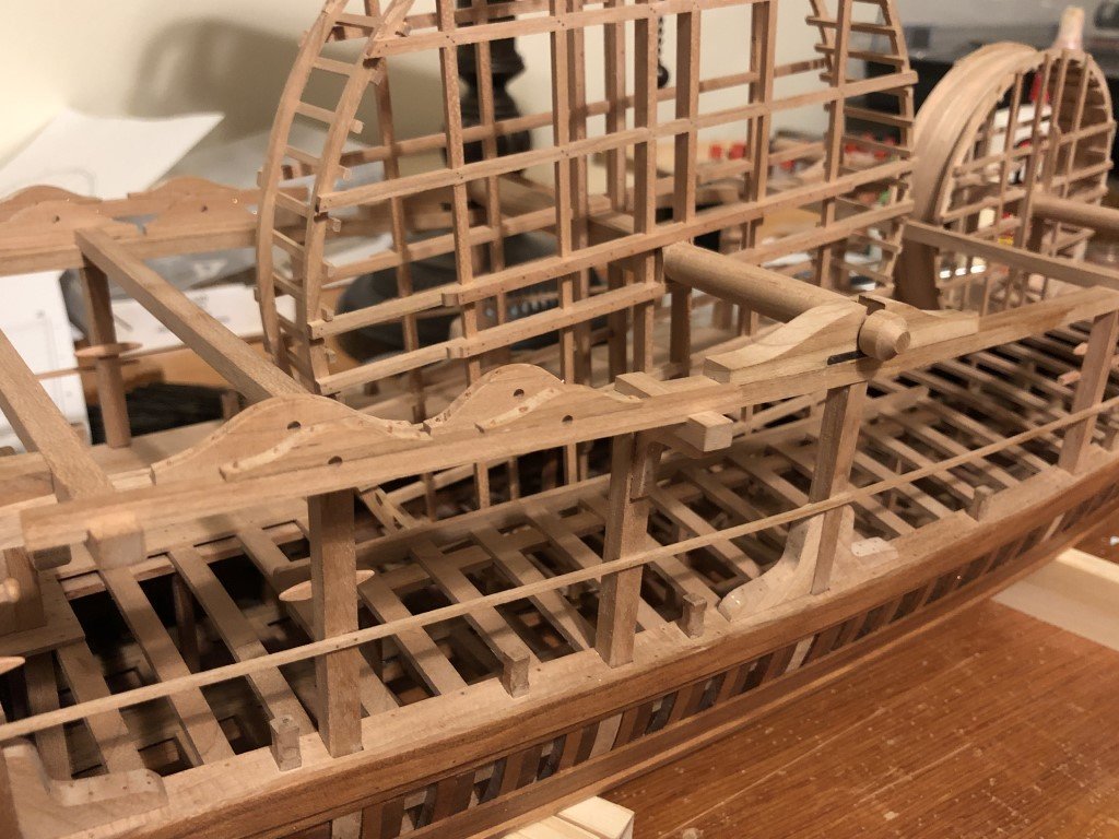
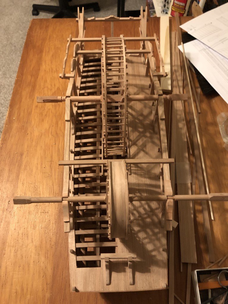
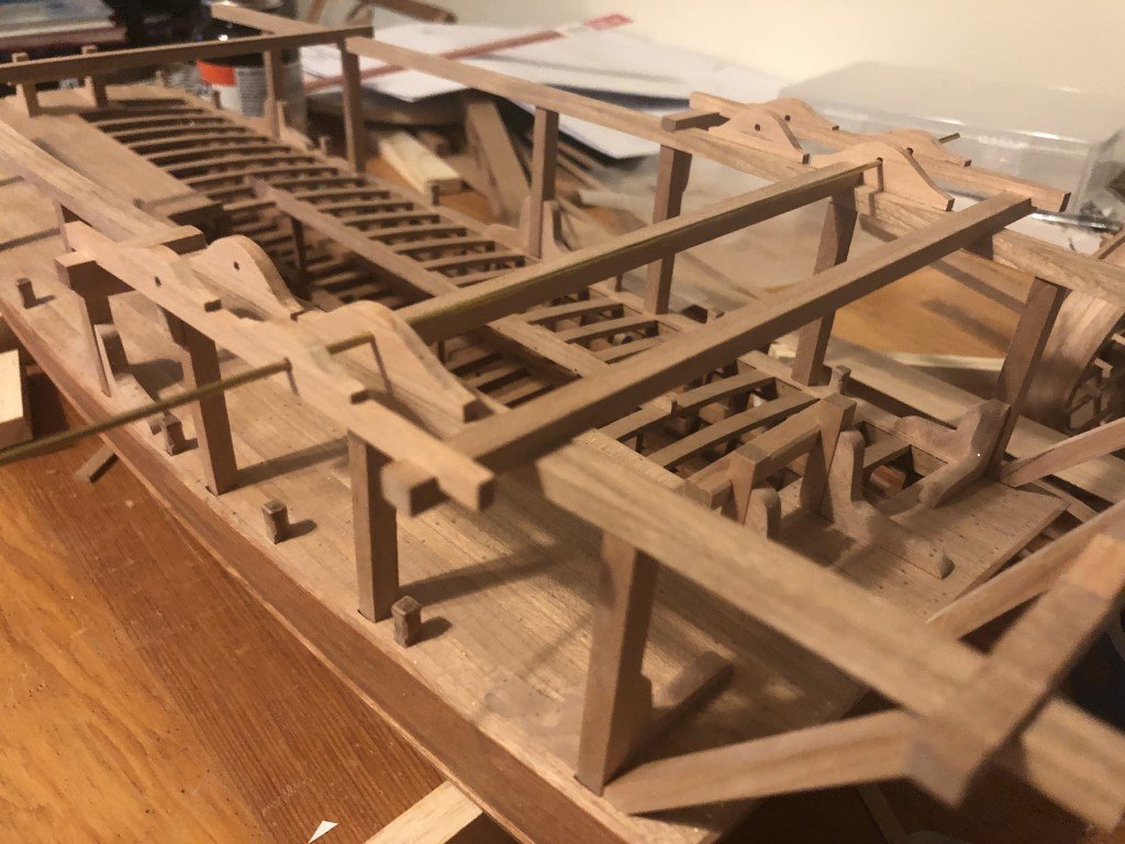
Over the weekend, guardrails and foot boards were added to the superstructure pillars. Also, I finished the last two knees - the ones that fit onto the slanted pillars. For some reason, these knees presented a great deal of difficulty for me to get all the angles right. Quite a few attempts were made before I was able to make a pair that I was willing to attach to the model.
Today I began work on the wheel bearings. The big wheel bearings are being done first because they looked to be less complicated than the small wheel bearings. The main challenge being that the bearings have footprints that match the curve in the superstructure carling (i.e., the bases are not rectangular) and the required shape looks to be more pronounced for the small wheel bearings than that for the big wheel bearings. Also, because of the carling / base shape, the recesses in the bearings need to be milled at an angle so that the wheel axles embed properly.
-
On to a better subject!
Today I spent time fabricating components that will support the scoop guides. Here are the parts before installation on the dredger. I connected the smaller roller pin supports onto the external guide beam before drilling holes for the pins. I saw no other reasonable way to have half the hole half above (and half below) the joint.
The external guides / beams were then installed. This was easy because the notches placed everything into the right place. I then went to install the inside guides. Note that they come in two sizes with the smaller ones forward; also the smaller ones are not symmetrical, there is a front and a back to these. I set these four guides onto the superstructure to check their fit and at first thought I had done something radically wrong as they looked to be sitting way too low. But then I looked through the holes from one side and was pretty sure I could see through all four. To confirm, I grabbed a piece of stiff wire and passed it thru all four - and yes, all was as it should be! I then use the wire to aid in gluing the inner guides in place. I threaded the wire in place, slid an inside guide into the open space between the superstructure and the exterior guide, spun it over to apply glue, spun it back, and set it in place. Repeat 3 more times and all done.
Later, hourglass shaped rollers will be turned to fit between the guides, as well as the pins that keep them in place.
-
I keep on feeling stupid for making that mistake, it's not like I don't know of the dangers - unfortunately, I have had family and acquaintances that have lost fingers to table saws and planers.
-
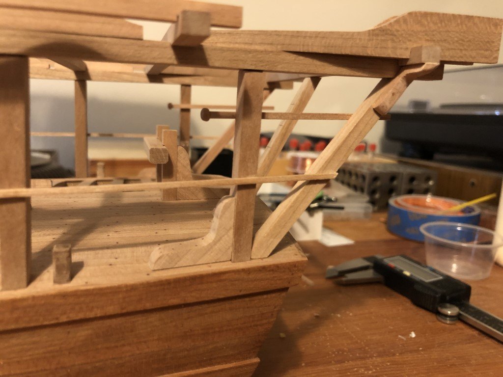
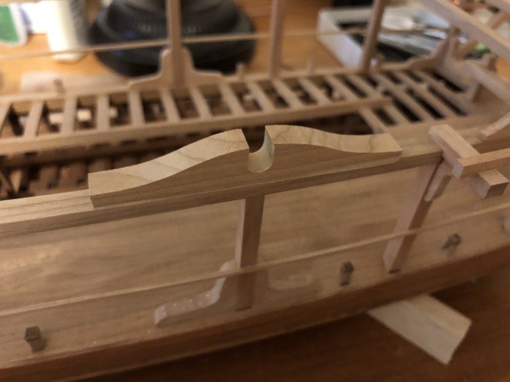
This evening I finished adding the three slanted pillars at the rear. Then I had time to make and install the mooring cleats that affix to the last superstructure cross-bar.
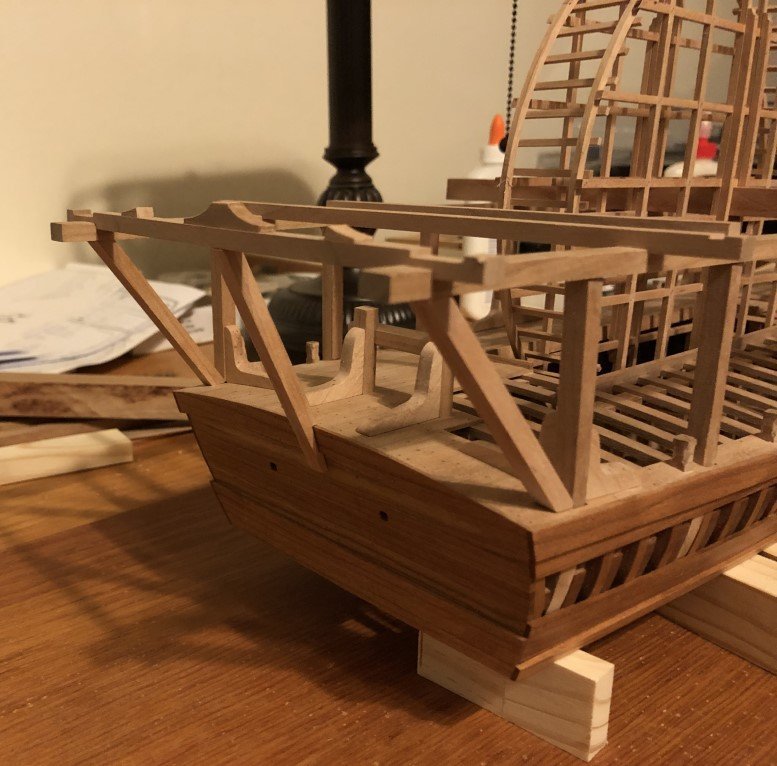
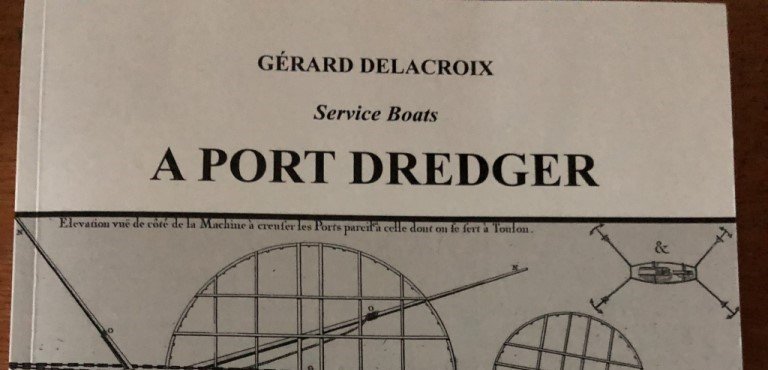
If I understand the monograph correctly, one way the dredger can be held in place during dredging operations is through the use of four anchors. Two in the front and two in back. The front two would have their anchor cables bound to the fore bit as expected; the anchors being set at angles radiating away from the vessel. Much like the small illustration on the cover of the monograph.
The aft two anchors also would have their cables connected to the bitts; however, they would not radiate like in the illustration as they would then foul the operation of the scoops. Instead the cables would go up and over the last cross-bar (between the cleats) and would then drop down into the water in such away that they would not foul the dredging process. The mid slanted pillar helps support the added strain from this method of mooring the vessel. Later, steps will be added to this pillar - a means for crew members to manage the mooring lines.
-
The mill is the model 5400 12" manual mill made by Sherline. I bought it (and one of their lathes) in 2012 and have not had many issues over the years. I have used the mill much more than the lathe. In hindsight, being enamored with Ancre publications, I now wish that I would have purchased the machines having metric scales instead of inches. I spend a good deal of time doing unit conversions!
About 4 years ago, I committed a huge power tool no-no with the mill. My eyesight is not great, so when I use the mill I typically take my glasses off to better see what I am doing. My hair was long at the time and I did not have it tied back / contained at all when I was working and yes, my hair got caught in the belt drive. I was so lucky that this is a hobby mill instead of a larger mill. Even so, the Sherline had plenty of power to pull me to the machine before I could flip off the switch. In this very short time period a good size chunk of hair was pulled out at the roots. It was a dumb move on my part as I am well aware of the hazards and try my best to maintain a high level of safety; but this one time I had rushed, didn't think, and clearly payed the price.
-
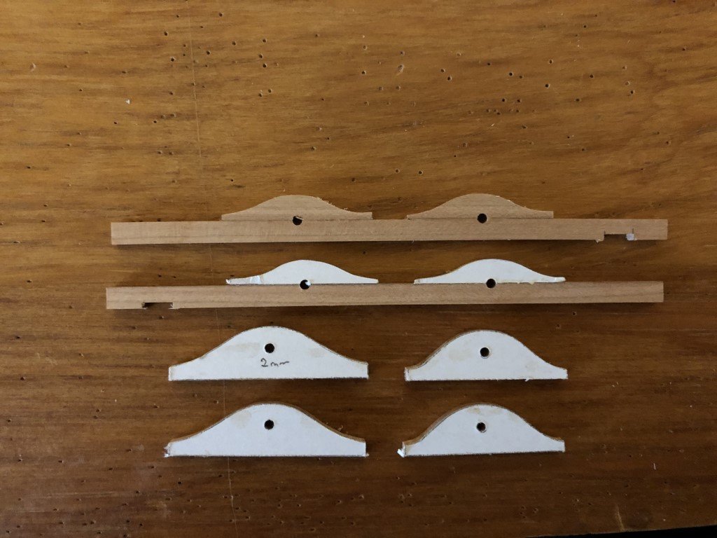
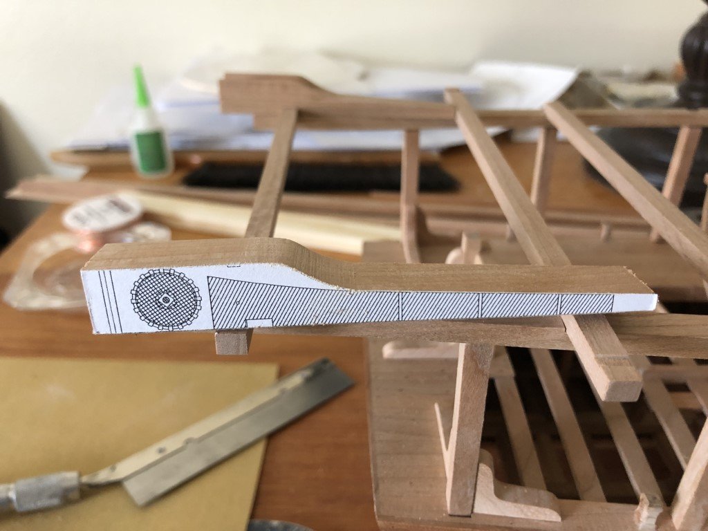
I wanted to share how I decided to make the davits. First of all, according to the monograph, the davits can be constructed in two different ways. One way is to make each davit out of a single piece of wood; the second is to make it out of three pieces - one central piece and two sides. The model presented in the monograph has davits built in three pieces; whereas I've seen the davits made in one piece presented in online build logs. I chose to make each davit out of one piece of wood. After I made this choice, I formulated several orders of operations in which to fabricate them. This is what I finally settled on. I don't know if it is the most efficient way to do the job, but it did seem to work well for me. The first attempt was a fail, but then I got the two I needed on the next tries.
I started by rubber cementing profiles of the davit to a length of wood 13.3 mm square in cross section. Note the center axis of the top/bottom profile is centered on the blank.
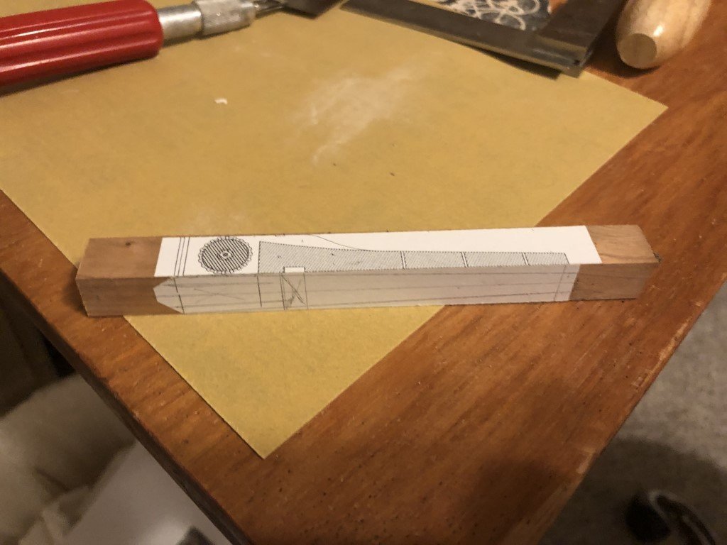
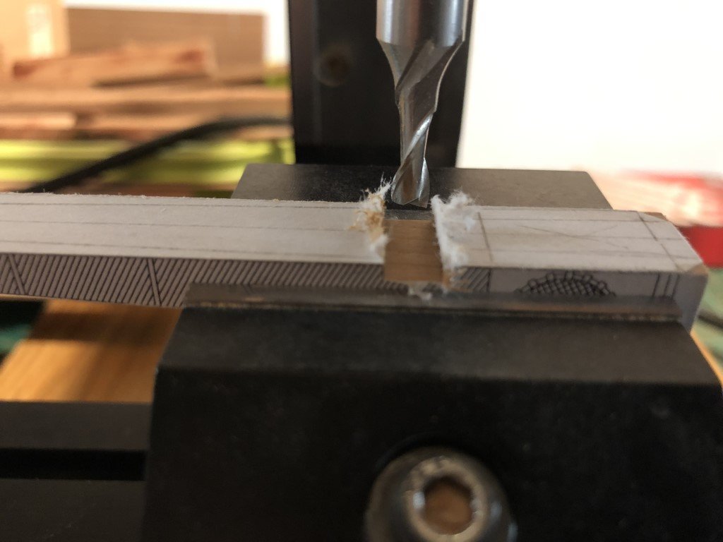
I then milled the top profile. Having the top/bottom profile centered let me mill this portion perpendicular to the blank. Here I have started to smooth the curved region, but you can still see the horizontal lines left as steps from each pass of the milling process.
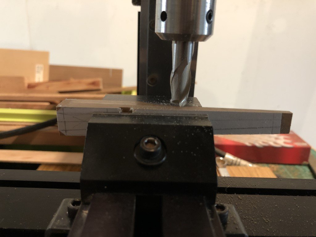
Next the bottom slot, where the davit locks on the superstructure was milled - note this is at an angle and there are specific left and right davits.
I then milled the two sides, the last milling operation.
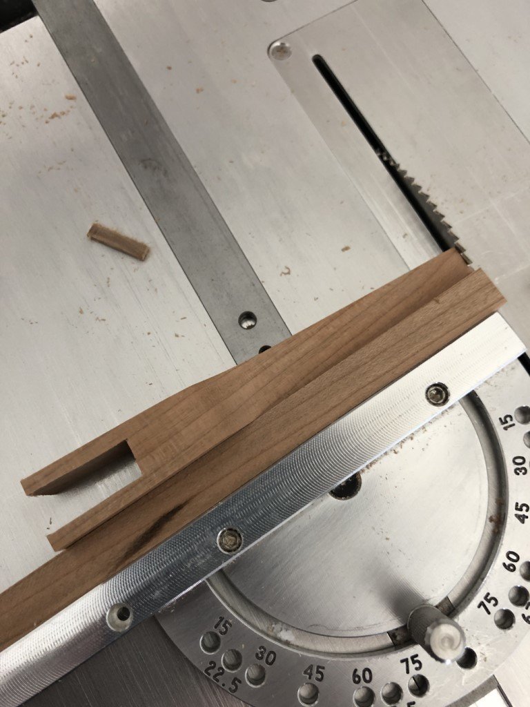
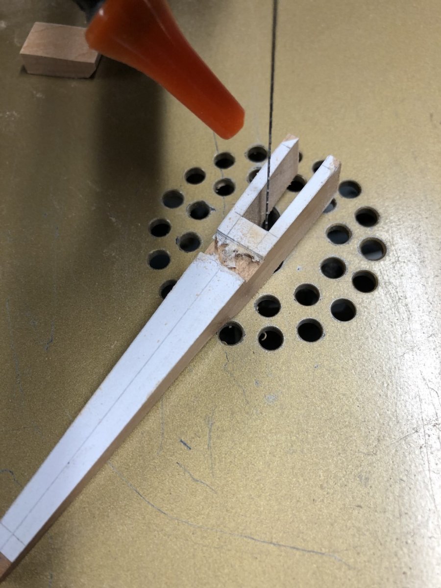
Using a scroll saw, the front space was opened up, after which the front length was shortened and then finished on a disk sander.

The back length was then adjusted so the davit fit correctly on the supperstucture.
Now it was time to remove some material in the middle to provide passage for the scoop chains. First I marked and sawed boundaries for the region to be removed.
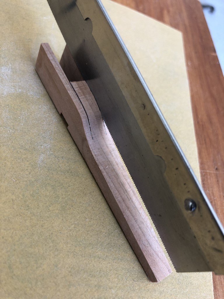
The unnecessary material was mostly removed with a small chisel.
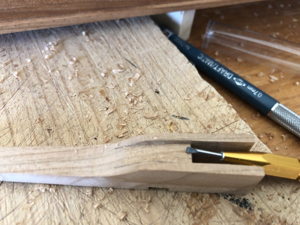
And the final shape of this inner region was developed using a sanding stick.
- AnobiumPunctatum, davyboy, ccoyle and 13 others
-
16


Le Pourquoi-Pas? 1907 by Greg Davis - Constructo - i.e., Why Not?
in - Kit build logs for subjects built from 1901 - Present Day
Posted
Several smaller deck structures have been added in front of the kitchen area. The kit supplied windlass is not spectacular and was difficult to get to a passable state - it would have been nice if this had been done as a casting!