SJSoane
-
Posts
1,644 -
Joined
-
Last visited
Content Type
Profiles
Forums
Gallery
Events
Everything posted by SJSoane
-
 just like being in the actual ship, except for the giant clamps taller than a man!🙂 Beautiful work and photos, Gaetan. Mark
 -
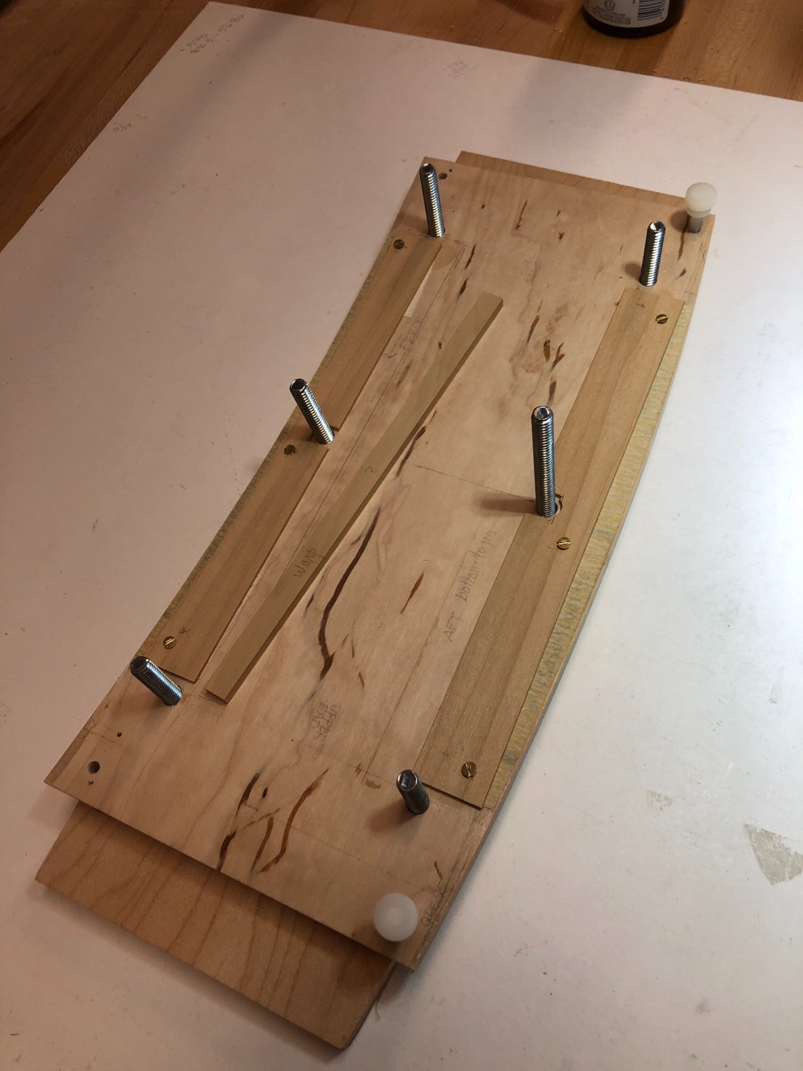
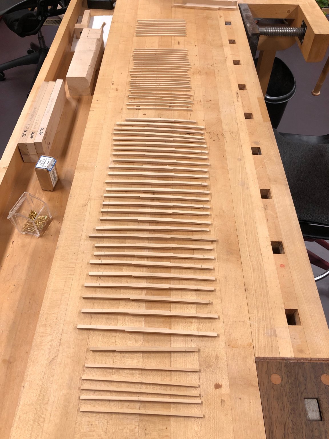
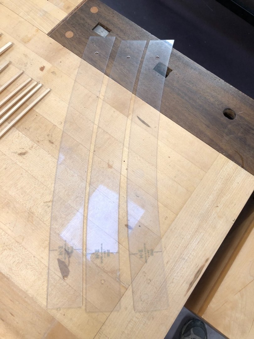
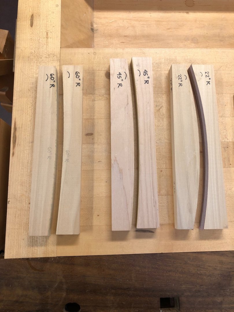
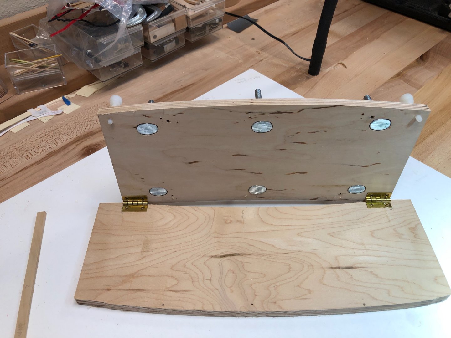
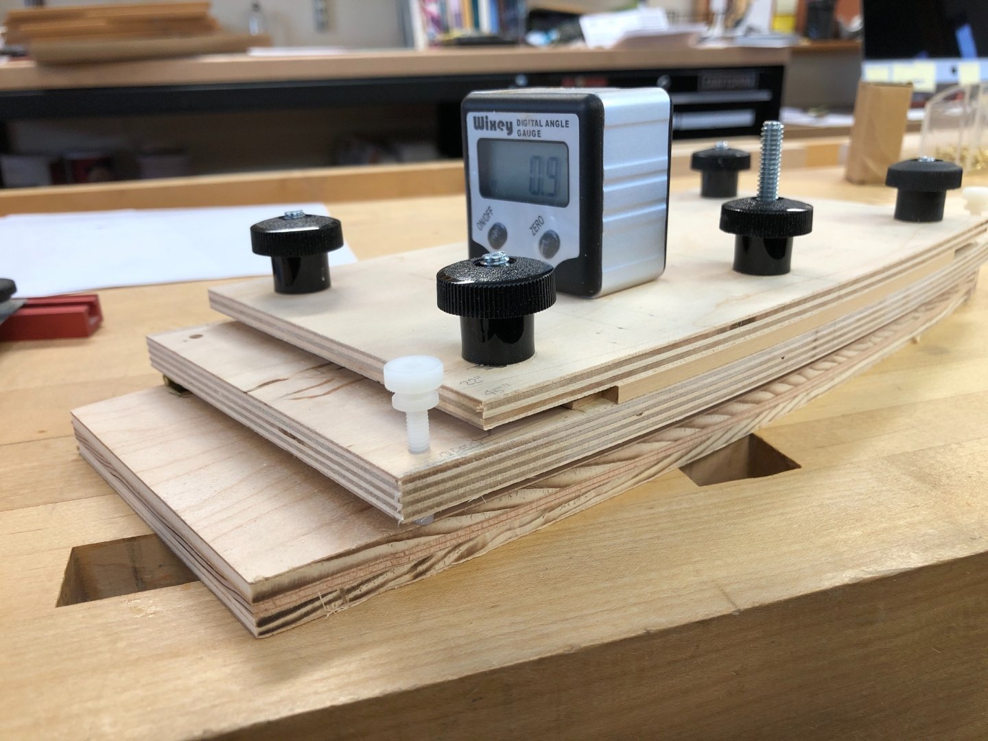
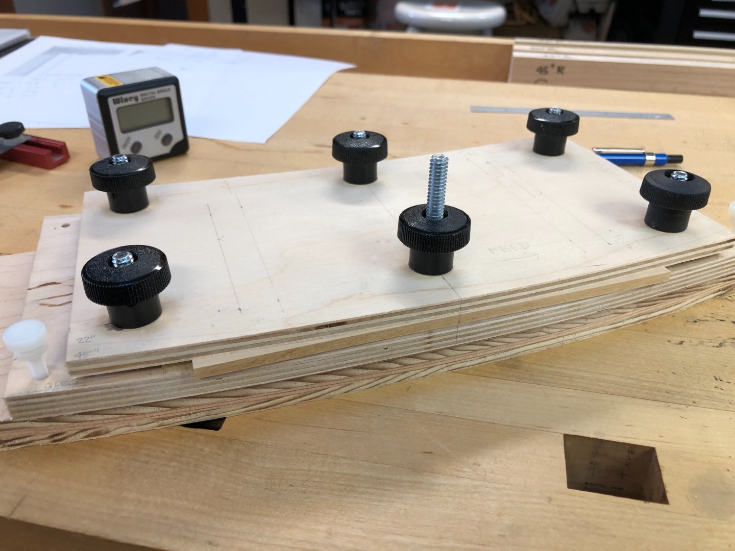
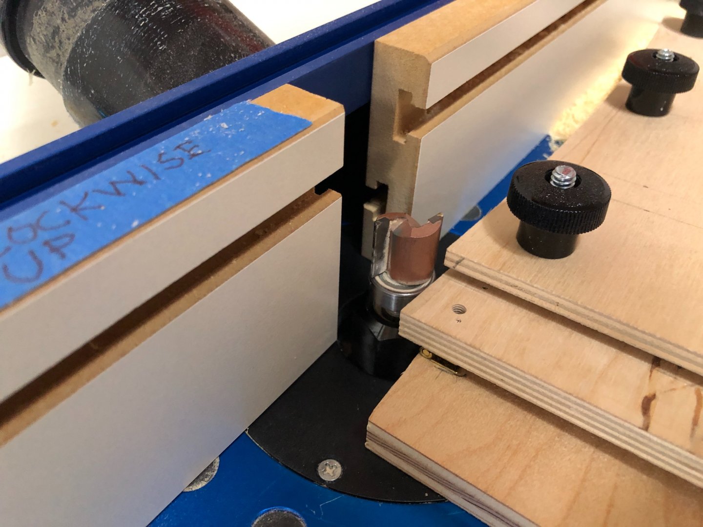
Hi Greg, when I started looking at the finish joinery and bulkheads, it began looking like more familiar territory for me. Besides the human factor, I realized that much of the detail was inspired by Classical architectural design, in the columns and pilasters on the bulkheads particularly. Some contemporary models and drawings I looked at were pretty fanciful in their interpretations of the traditional Classical orders (like Tuscan, Corinthian, Doric, Ionic), while others were pretty accurate. The rules in architecture are very precise in proportions and shapes of mouldings. I suppose the officers came from an upper class used to living in Classical houses, and wanted something like that in their own quarters. So finally moving on from drawing, I fabricated more beams while the garage is not too cold to work on the router table. I refined my jig, and it worked like a charm to crank out all of the upper deck, forecastle and quarterdeck beams. The jig has to do several things: 1) cut a smooth arc on the upper surface; 2) cut a smooth arc on the lower surface concentric to the upper surface; and 3) cut these surfaces with the correct angle at every beam location, which gets increasingly steeper towards the bow and stern due to the sheer. Getting the right curvature for the beams on each deck level starts with finding the rise at the center of the beams at their widest point on the given deck. This comes from the drawings or specifications. I then drew this curve on blocks of wood. I was fortunate to obtain an old set of drafting curves, which makes this simple; but arcs can also be constructed by traditional means. I then cut the curves on the bandsaw, and rubber cemented sandpaper to one side. I used this to smooth the opposite side, then put sandpaper on the smooth block to clean up the first block. When this is complete, you have a set of convex and concave blocks at the correct radius, which are very accurate and smooth arcs because rubbing one lengthwise against the other cleans up any irregularities and forms a perfect arc of a circle. I use these all the time for sanding edges of planking, leveling decks, etc. For the deck beam jig, I used these to form a convex and concave edge on a piece of plywood, I did this by attaching them to the plywood with double sided tape, and then running them against a piloted router bit on a router table. I then installed spacers, first one with a straight edge for cutting the initial convex edge, and then a curved one for cutting the concave edge (because the beam now has a convex edge after the first cut, which is placed against the concave stop for the second cut). You see below that I also rubber cemented sandpaper onto the jig, to provide more holding power so the blanks don't slide around when they are being cut. I then hinged this template to another piece of plywood, also cut with the concave and convex edges, but recessed well enough away from the template above so it would not run into the nut on the router. Its job is primarily to provide a smooth and stable surface for sliding on the router table. Two nylon screws allow me to adjust the angle of the template relative to the router table, thereby creating the angle needed for each beam due to the sheer. I used to use an angle gauge held against the drawings and then against the jig, but now I can get the angle off the CAD drawings, and use a digital angle gauge to measure as I turn the nylon screws. And then finally, a third piece of plywood is screwed down with the black plastic knobs, to provide a clamp to the workpiece (a scrap strip of wood the same thickness as the beams is put in the clamp at the opposite side to keep the upper plywood piece parallel to the template). We see it set up here with the first cut ready to go. And then the template is run against a piloted router bit in the router table. It took a bit of work to get all of the jig parts to work, but once set up, it allows a very rapid and precise cutting of beams, each one tailored to its unique location in the sheer, and with parallel surfaces of the correct radius. Here are (from top to bottom) the beams for the forecastle, the quarterdeck, and the upper deck, including the half beams at the aft end of the upper deck. I took extra care in marking out on each beam which edge should be convex, and also the direction of the angle on the end. The danger of a jig is that you automatically cut, remove, add next, cut, remove, etc. and it is so easy to get things turned around if you are not scrupulous about keeping everything in the same order. Having a visual clue to the correct orientation when putting in a blank helps keep things straight. Once each set of beams for a given deck was complete, I took the jig apart, recut the concave and convex edges with the radiuses required for the next deck, and then put it all back together again. Those with a mathematical outlook will realize that my upper and lower surfaces are not exactly concentric, since they are the same radius but the moulded distance of the beam apart. I decided at this scale that it would not be significant. So my only remaining challenge is how to store all of these beams so they don't warp. How does one sticker so many small pieces?🙂 Mark


-
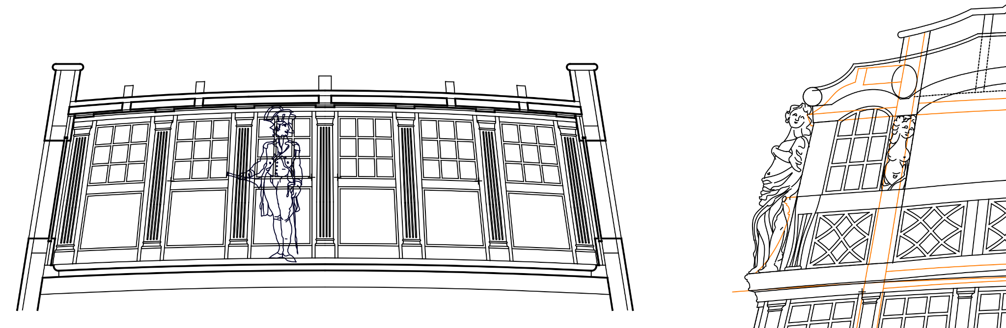
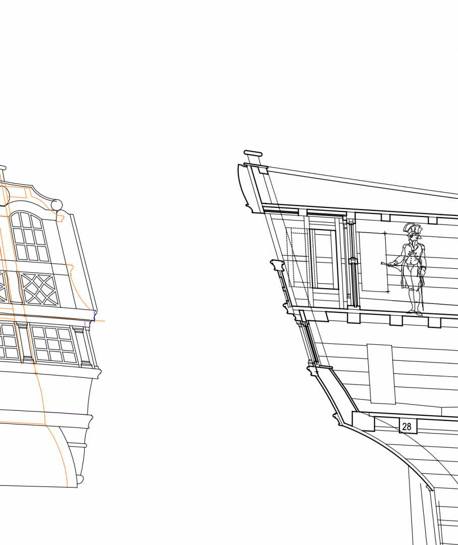
druxey, I was hoping for a 1:64 electric soldering iron...🙃 Continuing to draw more details, now the stern balcony and screen bulkhead. I learned a lot about some very refined design characteristics. Because the roundhouse beams round up higher than the quarterdeck beams, the transoms below the windows take a sweet curve split between the two. All of the intermediate window bars are equally spaced between the two. The doors in the last bays at the outboard ends of the screen are disguised to look like the rest of the windows, with very thin rails framing the door window hiding behind the columns on the fore side of the bulkhead. And best of all, pocket doors to the quarter galleries from the balcony itself, which slide aft into just enough room in the panelling at the side of the balcony. You can see in the upper left sketch below how the door just fits between the hull frame and the finish panelling. this has to keep very thin so it does not intrude on inboard side of the fair damsel in the stern carving, sketch to the upper right. And the bottom sketch shows just how close the sliding door (slid aft position in dotted lines) comes to the end of the panelling. Oh, and the sash window to the wardroom one deck below has a little pocket between the transom and the aft most mouldings, so it can slide up 8" for some fresh air. There was some very sophisticated design work going into this finish joinery at the stern. There is something kind of thrilling about this detective work, reconstructing the design of someone working 270 years ago. It is almost like sitting there with him at the drawing board, as he thinks through how to make all of these parts interact nicely with each other. Mark

-
druxey, I just need to figure out how to hold the miniature red hot iron...😉
-
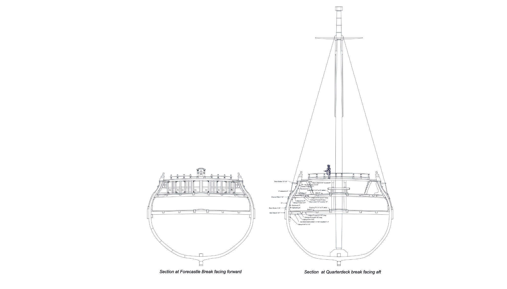
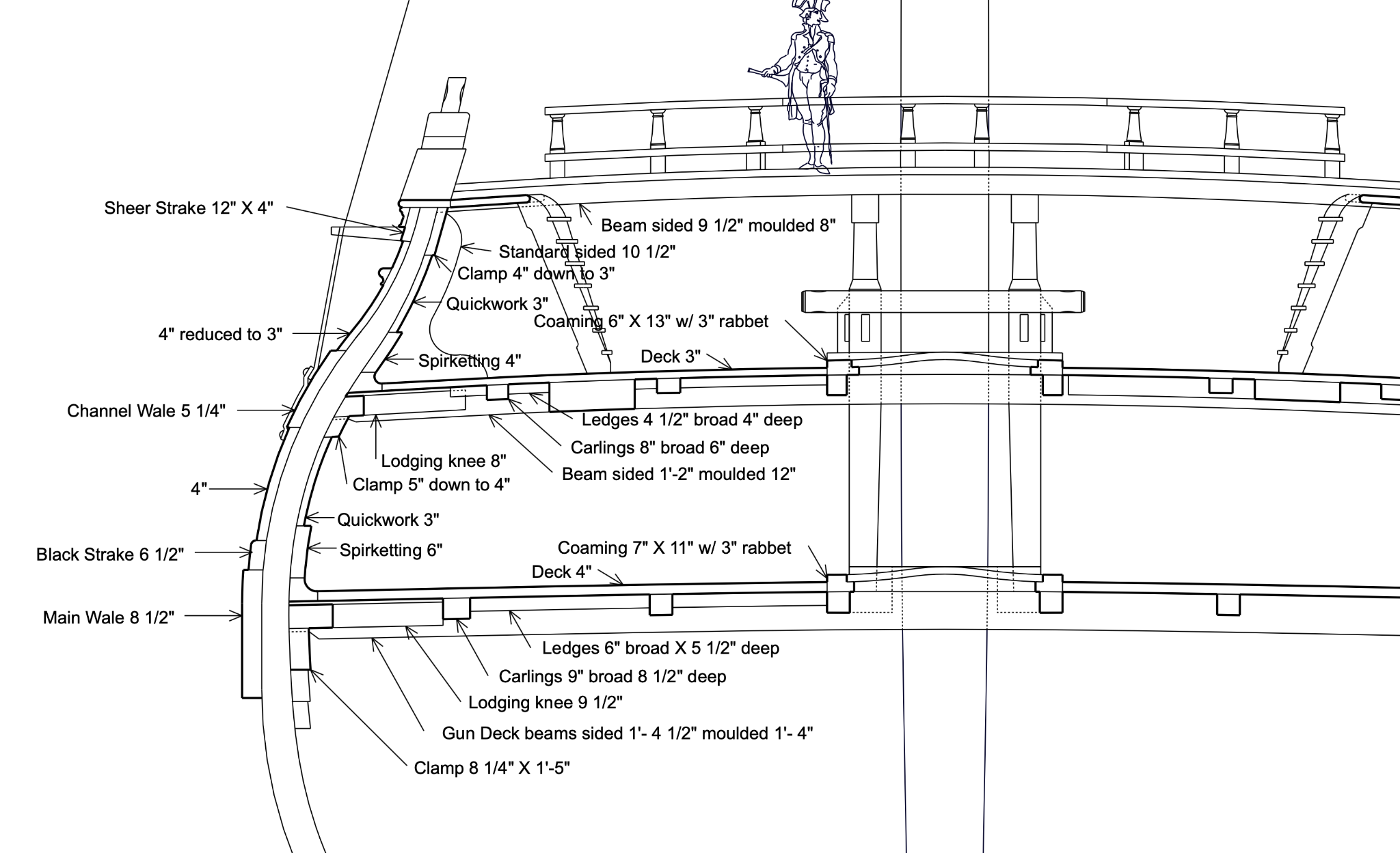
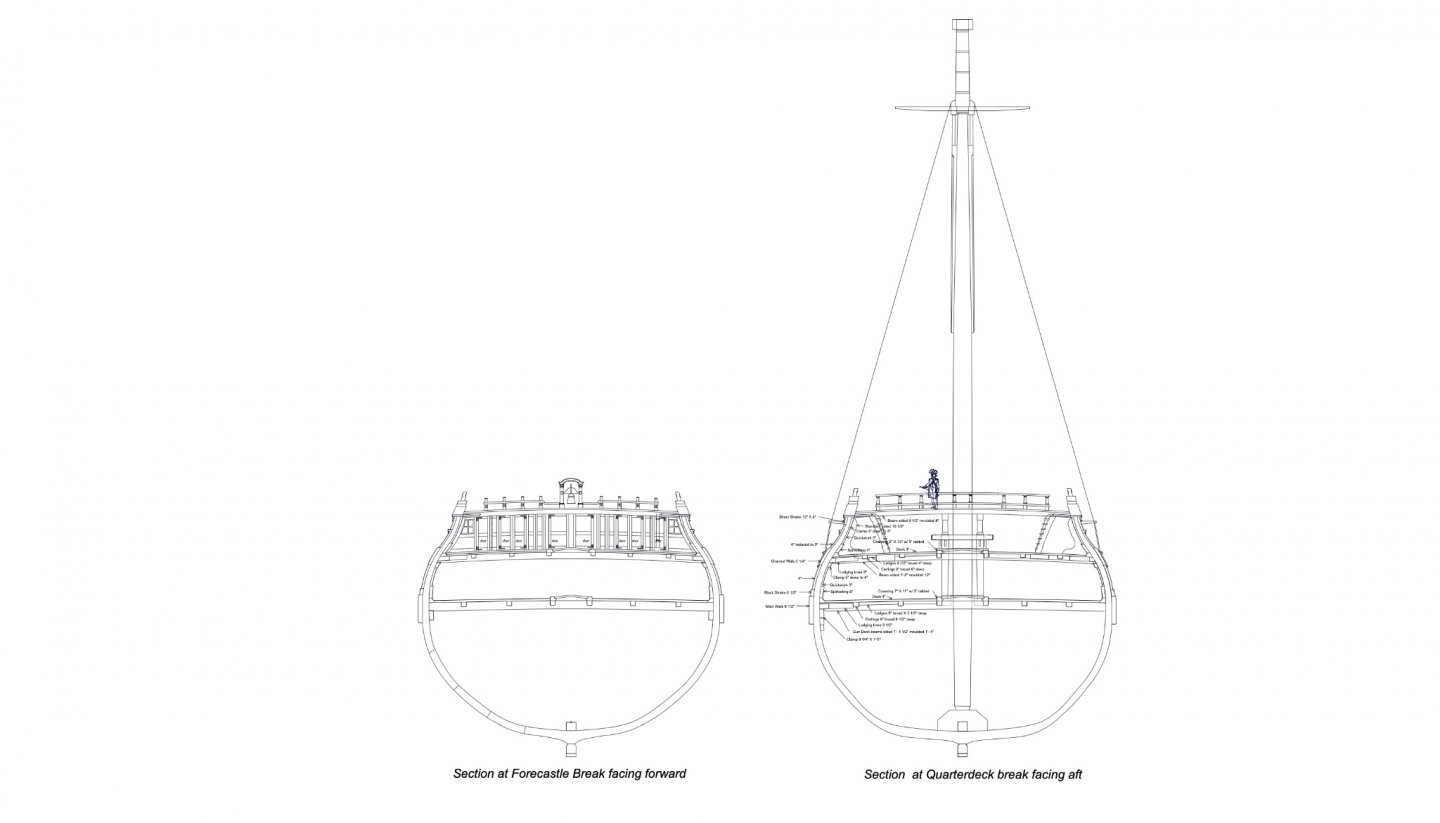
Hi Gaetan, thanks so much for the photos. That really brings a drawing to life, showing how common this device must have been in a lot of different locations and for different tasks. I just keep drawing away, deciding to get more things worked out on paper before cutting more wood. The cross sections are exceedingly helpful for refining a lot of the details. I should have done this years ago.... Now I have a clear record, in one place, of the sizes of things as I work my way upwards. By the way, in the specifications for the Marlborough, dated 1763, there is an interesting description of the beams and clamps that I remember Gary (garyshipwright) pointing out several years ago--I just didn't understand it at the time, but now I think I do. Gary, you so far ahead of me in so many ways! Taking the gun deck, for example, the lodging knees are set 1 1/2" below the top surface of the beams, to ensure more air circulation between the knee and the deck above, to avoid rot. The upper surface of the clamps touch the lower surface of the knees, and are themselves 1' 5" deep. But this means that the beams, moulded 1'-4", would cut excessively into the clamp, causing a structural weakness. So the beams are bearded up at the extreme ends (12" from the end), to cut into the top of the clamp by only 1". I did not understand the logic of this years ago, but now I do. The clamp is providing great longitudinal structure, and cutting large notches into its top surface would reduce the effective structure down to whatever was left below the notches. This needs to be minimized. At the same time, the structural capacity of the beams is mostly determined at the center of its span. Notches at the extreme ends do little to compromise the structure; although, it does provide a place for splits to start. The pillars at the centers would provide a lot of additional support at the center, reducing the load that has to be carried at the end over the clamp. An interesting balance of avoiding rot, while maximizing structure. They were clever guys, those shipwrights! I already installed my clamps several years ago, and placed them without this refined detail, so they are lower by a few inches. I am not inclined to move them at this point. So my drawings will reflect the true detail, but the actual model will be simplified. Don't tell anyone! Mark

-
Thanks so much, Zeh, Dafi's log is well worth looking at. His little figures really bring the deck activity to life, and the jack screw clearly illustrates how the beams were lifted in order to pull out the pillars. Mark
-
Gaetan, it looks like that young child in the painting is about to do serious damage to the rigging! Your craftsmanship on the stairs continues to set the highest standard. And the photos give a nice perspective on this area of the ship. Well done! Mark
-
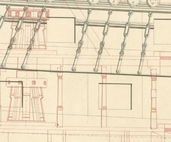
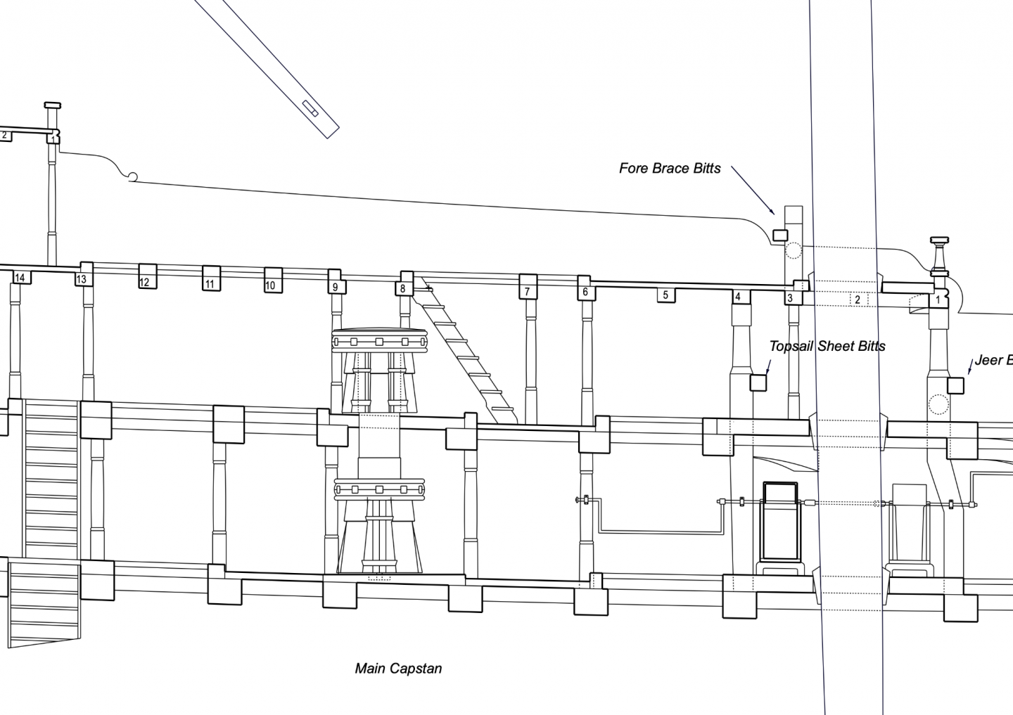
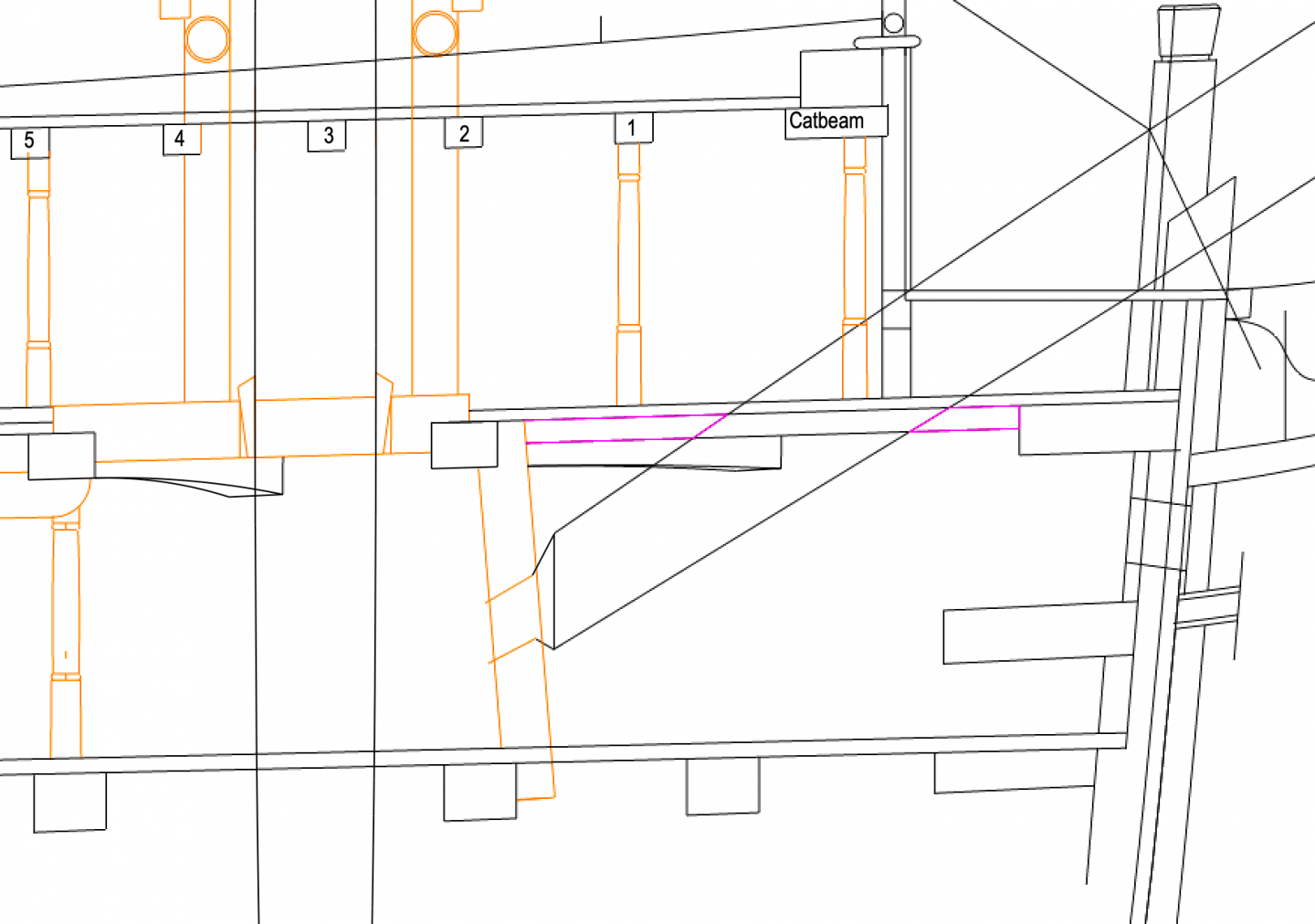
Looking again at the tops of the pillars in this image, I think the tops might be dotted lines because they are drawn the height at the centerline of the ship, but the beams are drawn at the side of the ship, covering the tops of the pillars in this view. I know in some cases in the Bellona, the pillars are at the center of the beam, so could not slide out the side. So there must be a tenon at the top as well as bottom, using the jack device to remove them. Except for the pillars that hit only partially, as seen in the far left here, or in some cases don't hit a beam at the top at all. I recall a story about Frank Lloyd Wright and his masterpiece house, Fallingwater in Pennsylvania, which has large concrete cantilevered decks over a waterfall. The story goes that the workmen did not want to go under the freshly poured concrete to knock out the form supports, for fear that it would collapse upon them. The architect, confident in his design, walked under and knocked them out himself. Now whether this story is true or not, the fact is that the decks did massively sag over the years, and had to undergo significant reconstruction a few years ago. So I wonder how much the guys cranking up a deck in a 74 worried about breaking something in the process?😗
-
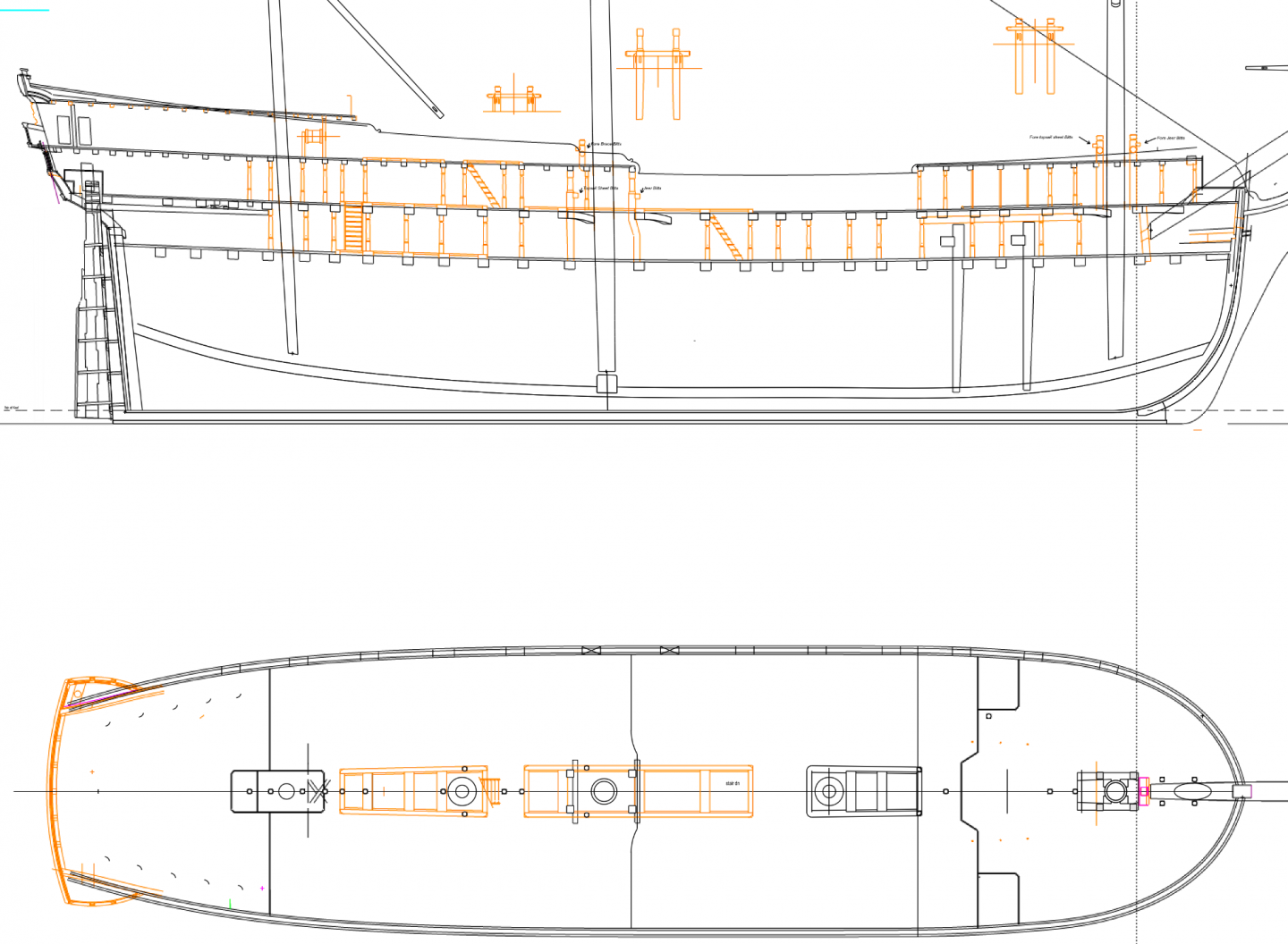
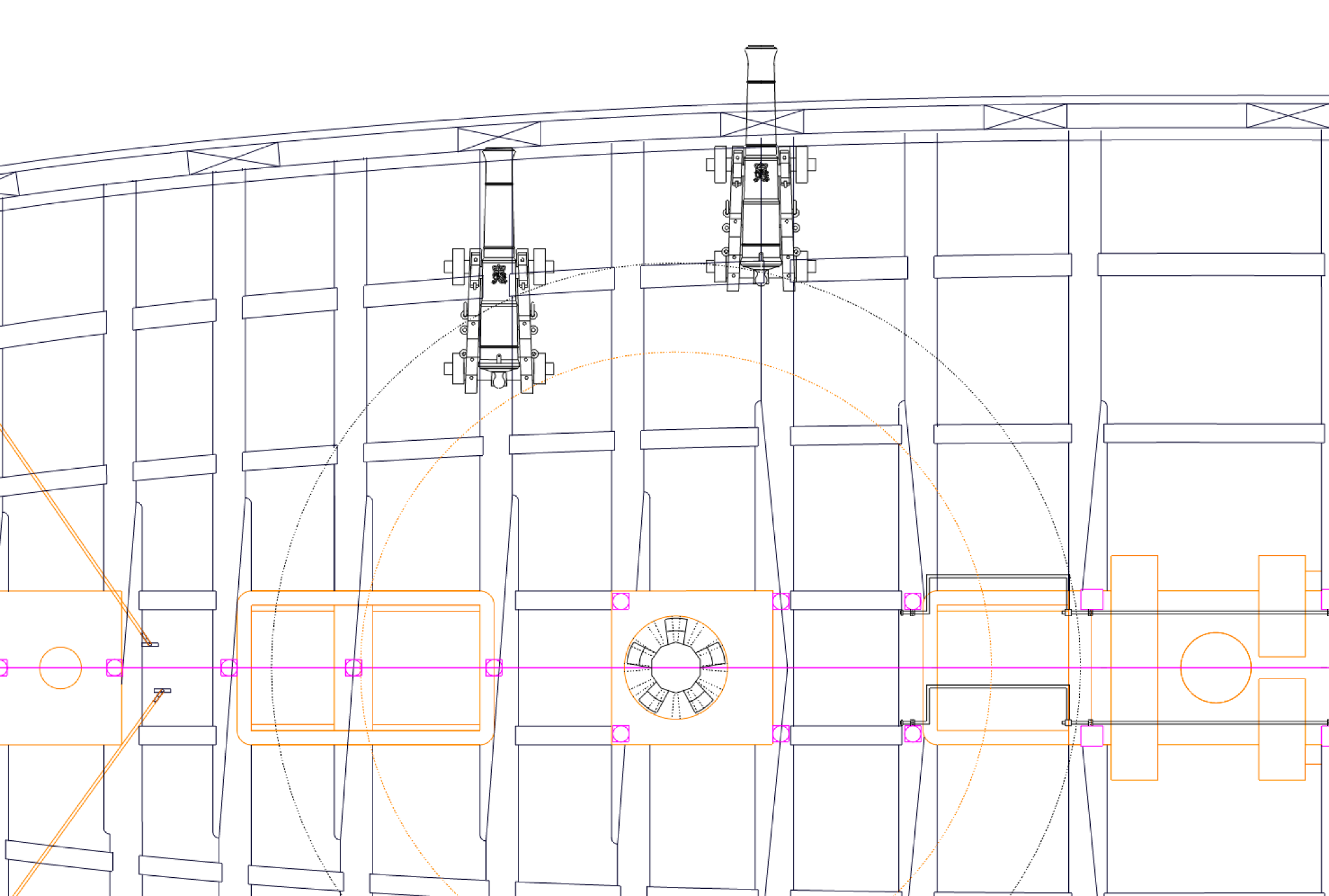
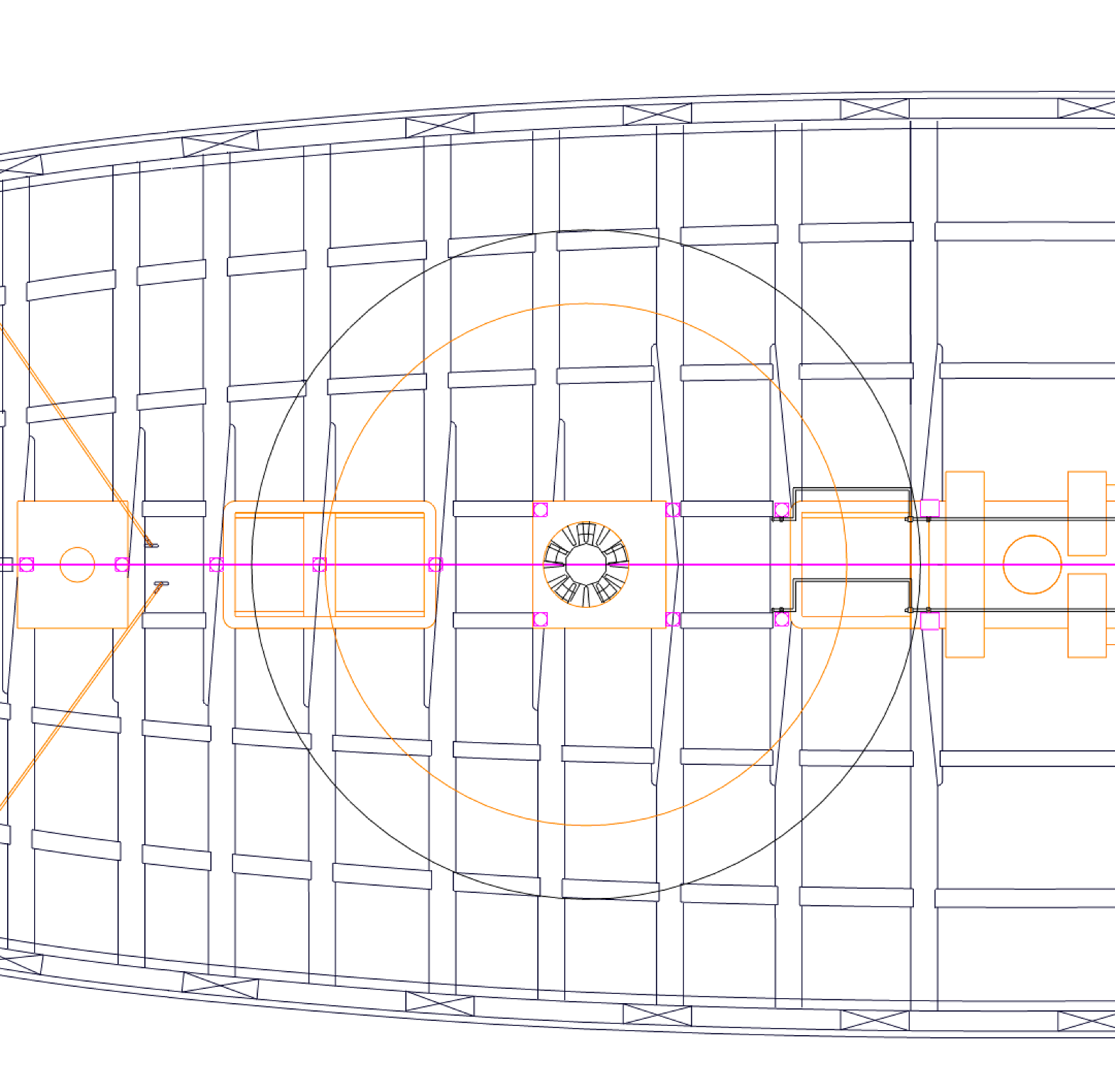
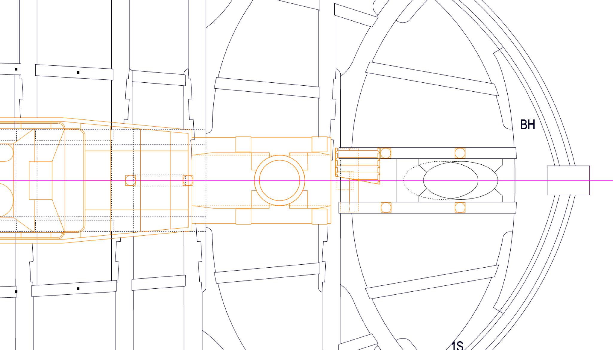
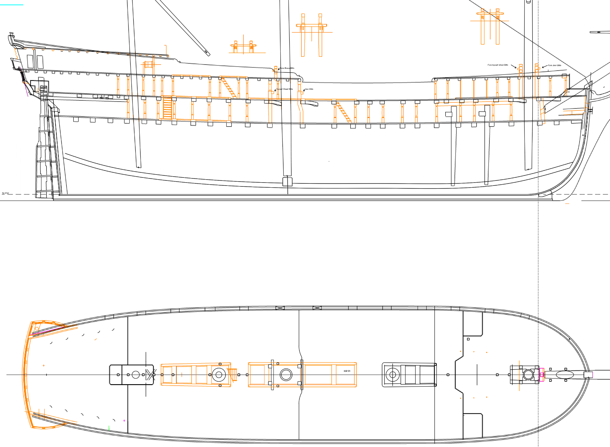
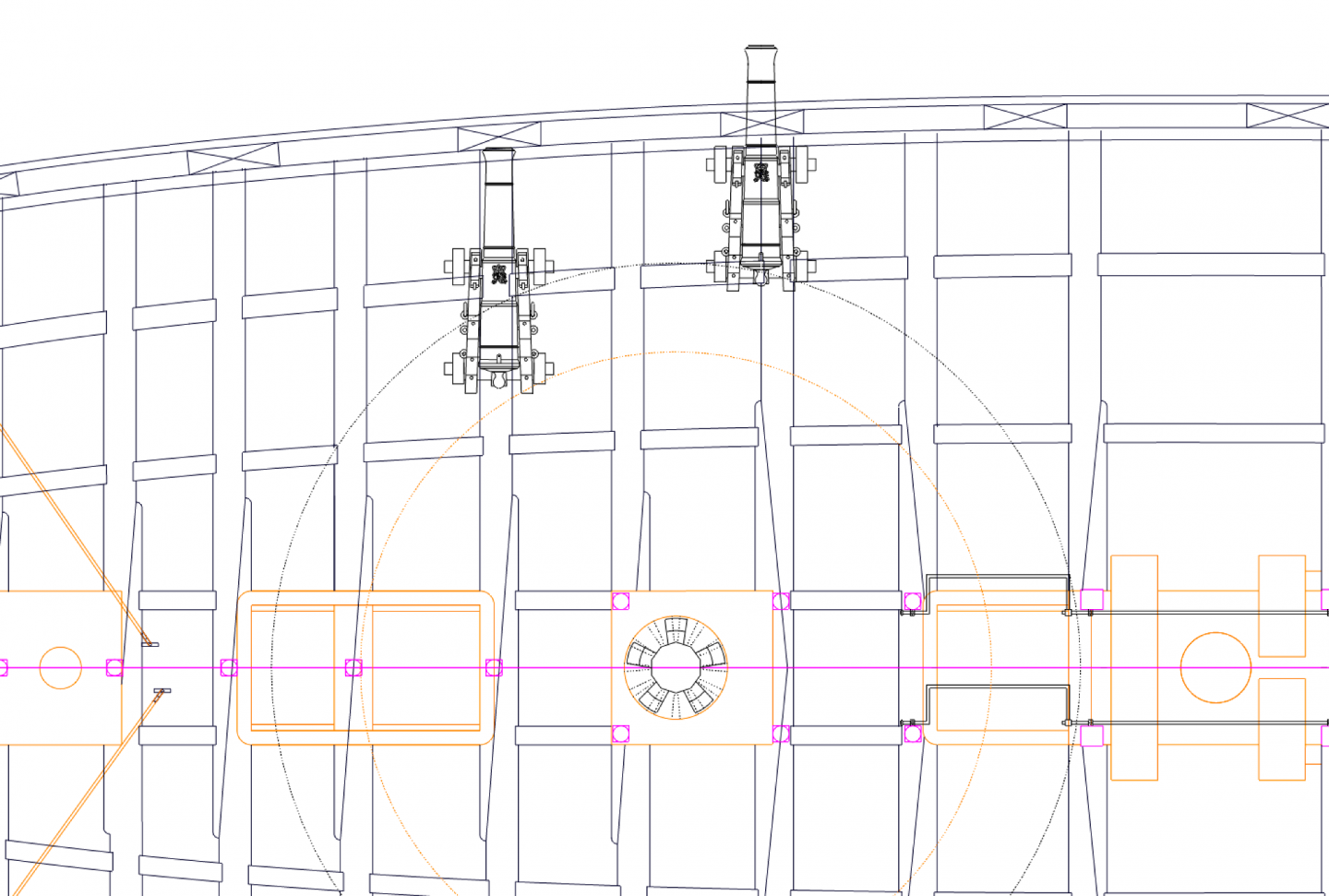
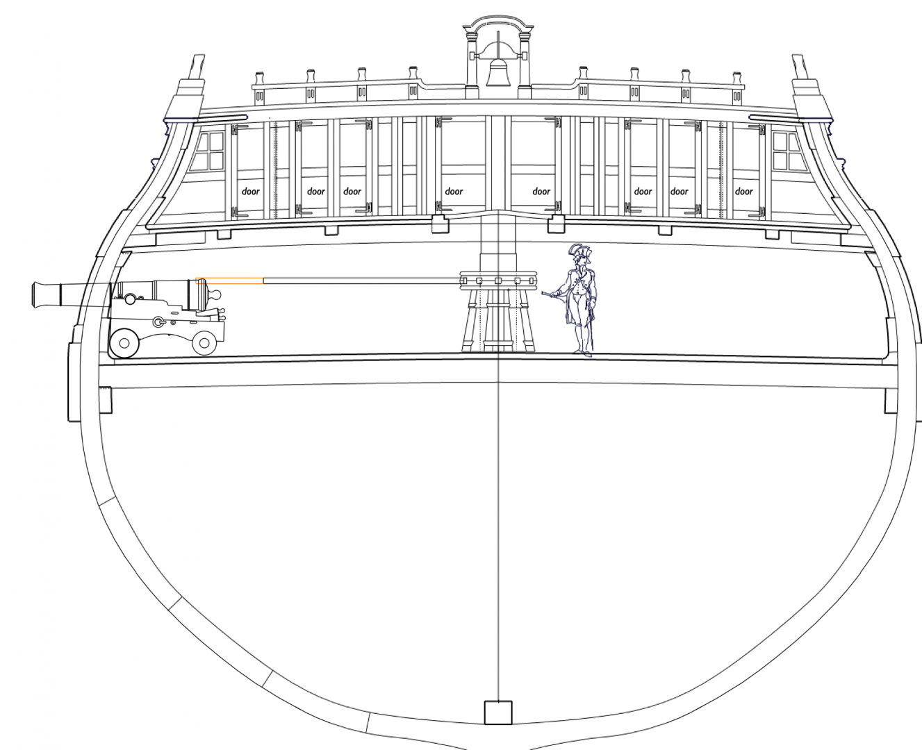
Thanks, druxey, good thinking! Here are guns run in and out, in plan: And here is a gun run out in section. The black line shows Lavery's length, while the orange shows the additional length of Goodwin. They would be hard-pressed to use the capstan with guns on the deck. at the longer length. So I think I will use Lavery's length, although I wish he had given a source.... Gaetan, thank you for the photos. You are right, these are good examples of something so obvious to the shipwrights that they probably never would have drawn them out. But it makes sense, and it would be very easy to lift the pillars out the way when the space was needed. Best wishes, Mark
-
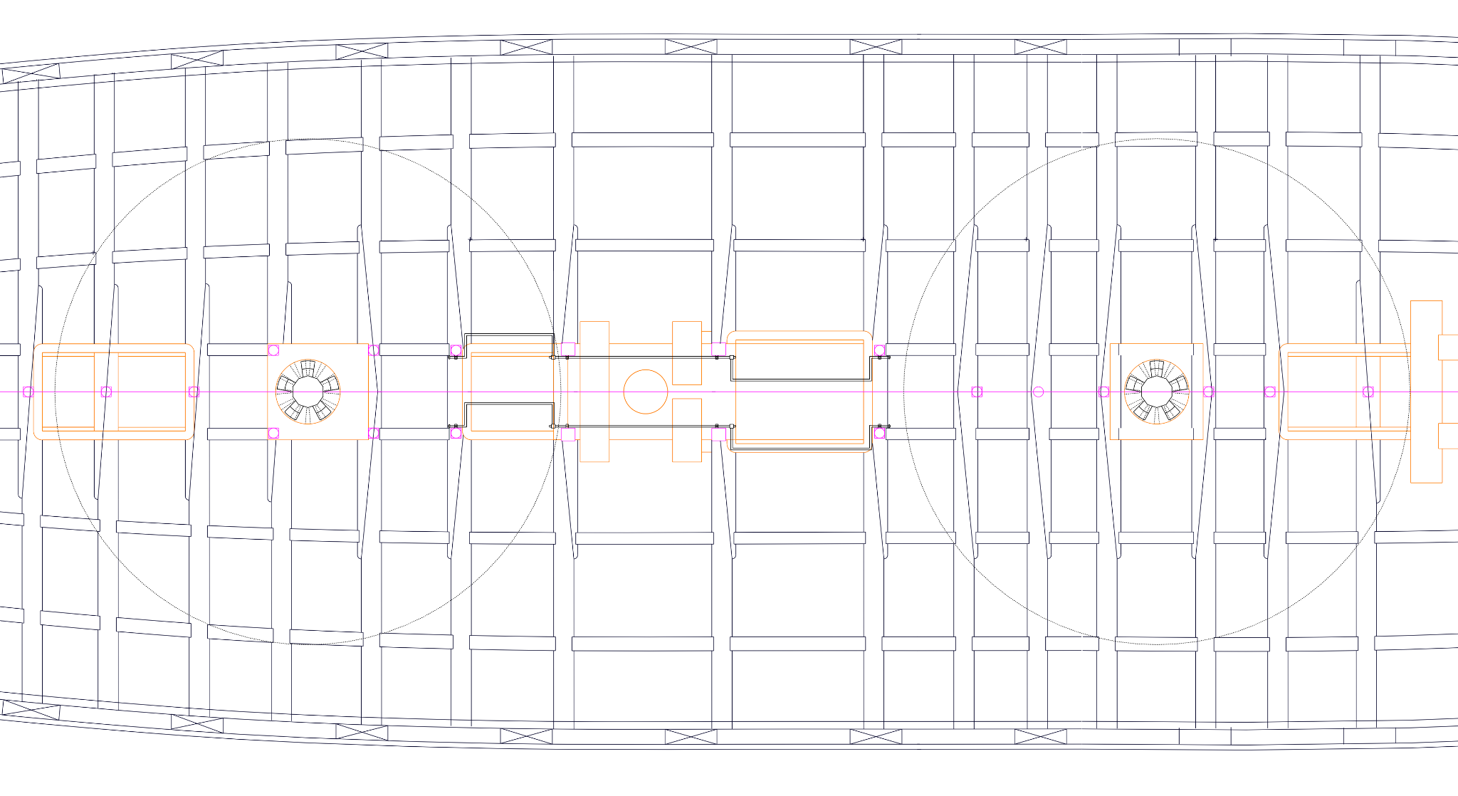
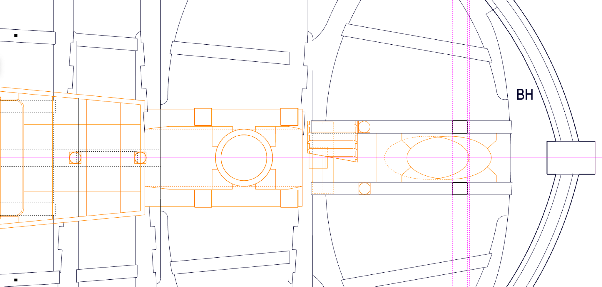
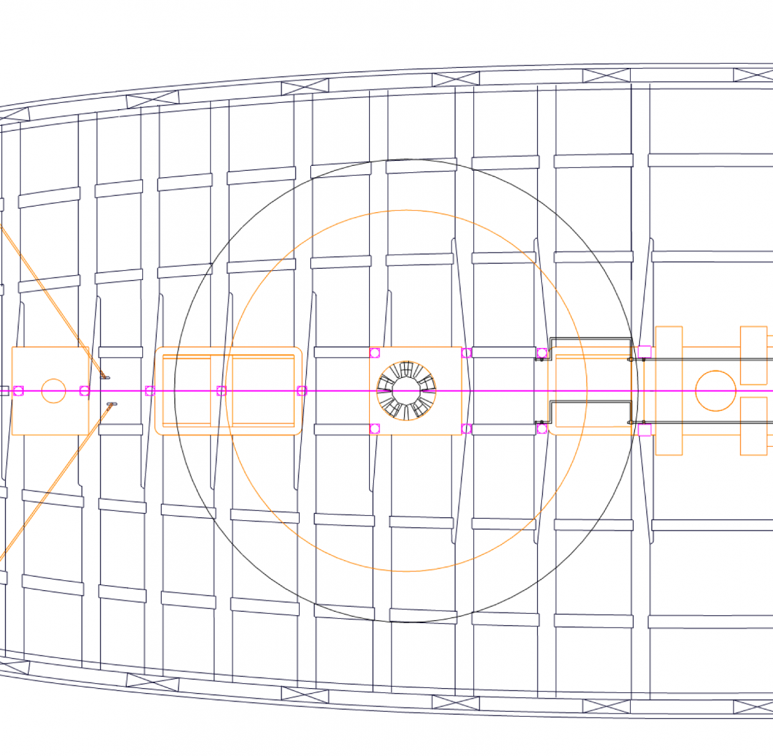
Gary, I would love to see that detail of the hinged pillars, if you ever come across it again. I have a couple of pillars that cannot sit directly under a beam because of something like a hatch below, and I am wondering how the pillar is attached at the top in these situations. Sailor, druxey points out that the pump brakes can be easily removed, and they can also be connected or disconnected in various ways so that both can drive both pumps, or one side can drive one side, or one side can drive both pumps. So I imagine if they needed to use the capstan and also pump, the fore brake would be used to drive both pumps while the aft brake was temporarily taken away to leave room for the capstan bars. While looking at this further, I discovered that Brian Lavery's book on the Bellona calls for capstan bars 11'-6" long (p. 69), while Goodwin's Construction and Fitting book calls for bars one third the beam of the ship. The drawing below shows the result of Lavery's dimension in orange, and the Goodwin dimension in black. Goodwin's dimension does get awfully close to the immovable bitt pins, so maybe it is a little closer to Lavery's dimension. Does anyone have a way to resolve which it is? I tried looking a photos of contemporary models showing the capstan bars, but it was inconclusive for me to see. Best wishes, Mark
-
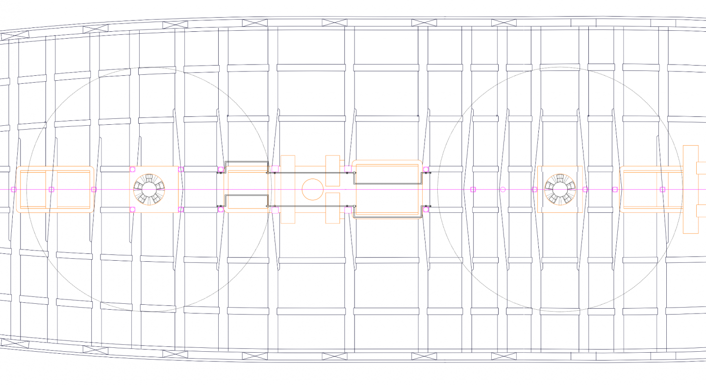
You are right, druxey, the bars JUST clear the bitt pins on the gundeck, the purple squares below. All pillars and pump bars removed will work. They were pretty clever, weren't they?
-
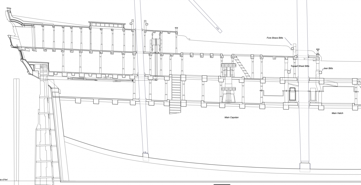
Thanks so much, druxey, Gary and Siggi, for your observations and help. Siggi, in all of the models you have looked at, was the Bellona unique in having so many pillars on the upper and quarter decks? It sure does look like a forest of trees on the quarterdeck, and in the captain's cabin... I am amazed as I start to finalize details on the Bellona how much I have not noticed in looking at these ship drawings and models all these years. You are all helping enormously as I try to work some of these details out. I am a little envious of the drawings later in the century that show so much more detail; the Bellona drawings were clearly rushed out the door with just the bare minimum of detail. But then, I would not have had as much fun over the years working out these details... I have been working away on the drawings, noticing for example that the sheaves under the steering wheel for the tiller rope have to be dropped below the carlings in order for the rope to clear the beam just aft (see below). I have also begun to wonder how I am going to rig the tiller ropes, when this assembly will be buried under two decks before the steering wheel can be attached. I may have to build the upper and quarterdecks together, working from aft. And realizing the main capstan on the gundeck has no clearance for normal length bars, which will hit the pumps unless they are very short:

-
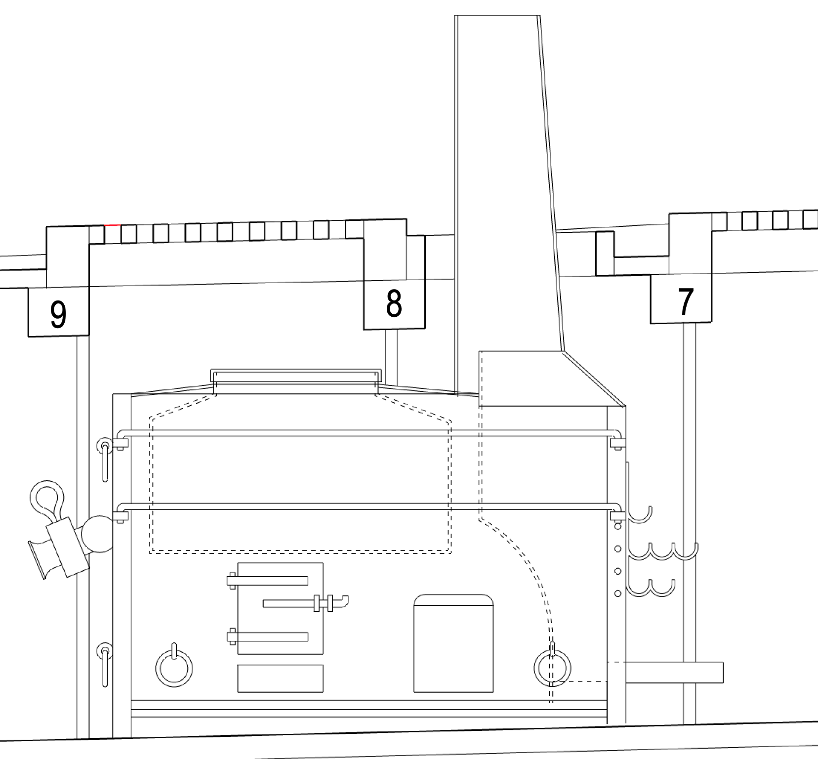
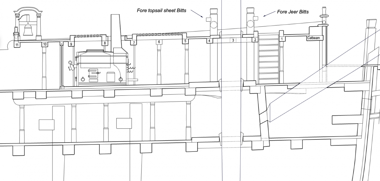
Oh, and one more curious detail. The models in the previous post show the chimney pipe for the stove as fully filling the opening in the deck. But when I draw the stove in section and also the opening in the deck as dimensioned in Slade's original drawing, there is definitely a large gap between the two. Bigger chimney, smaller opening?

-
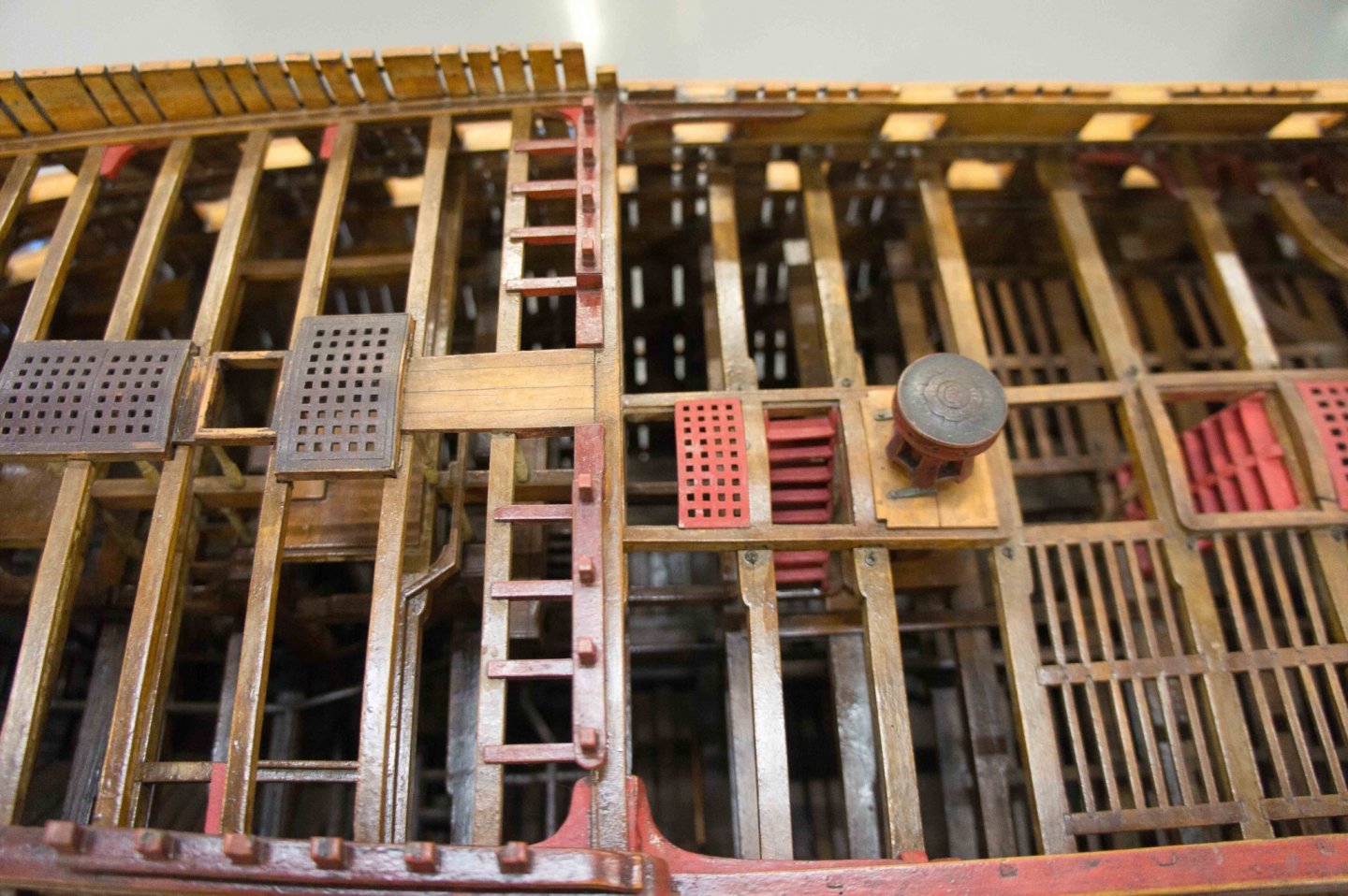
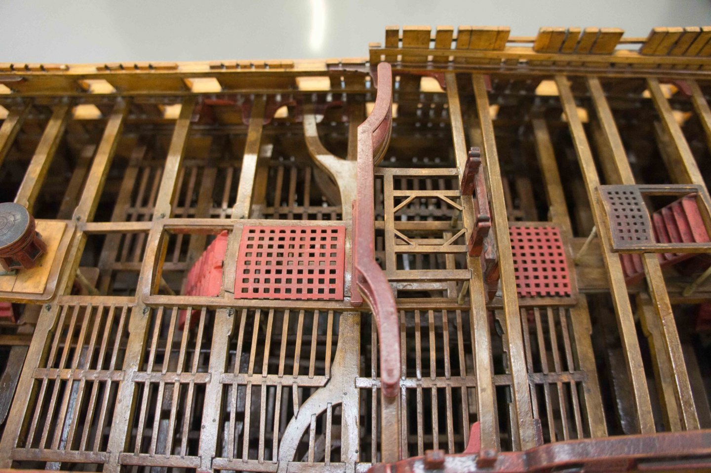
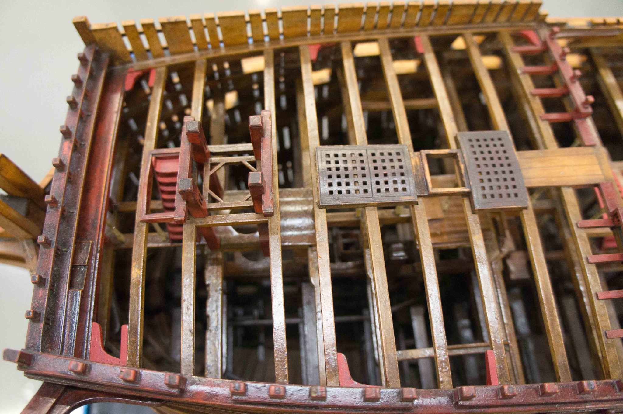
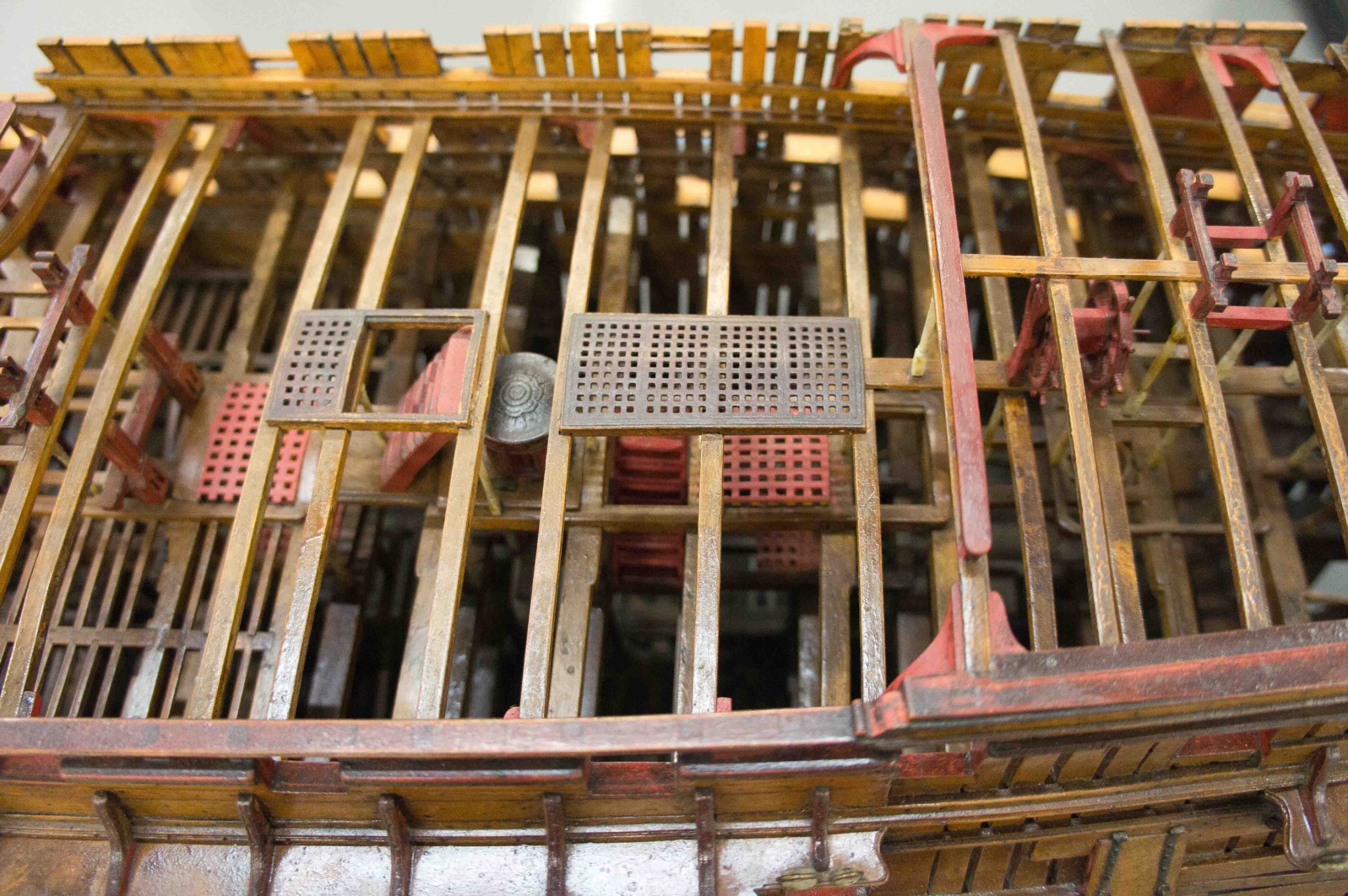
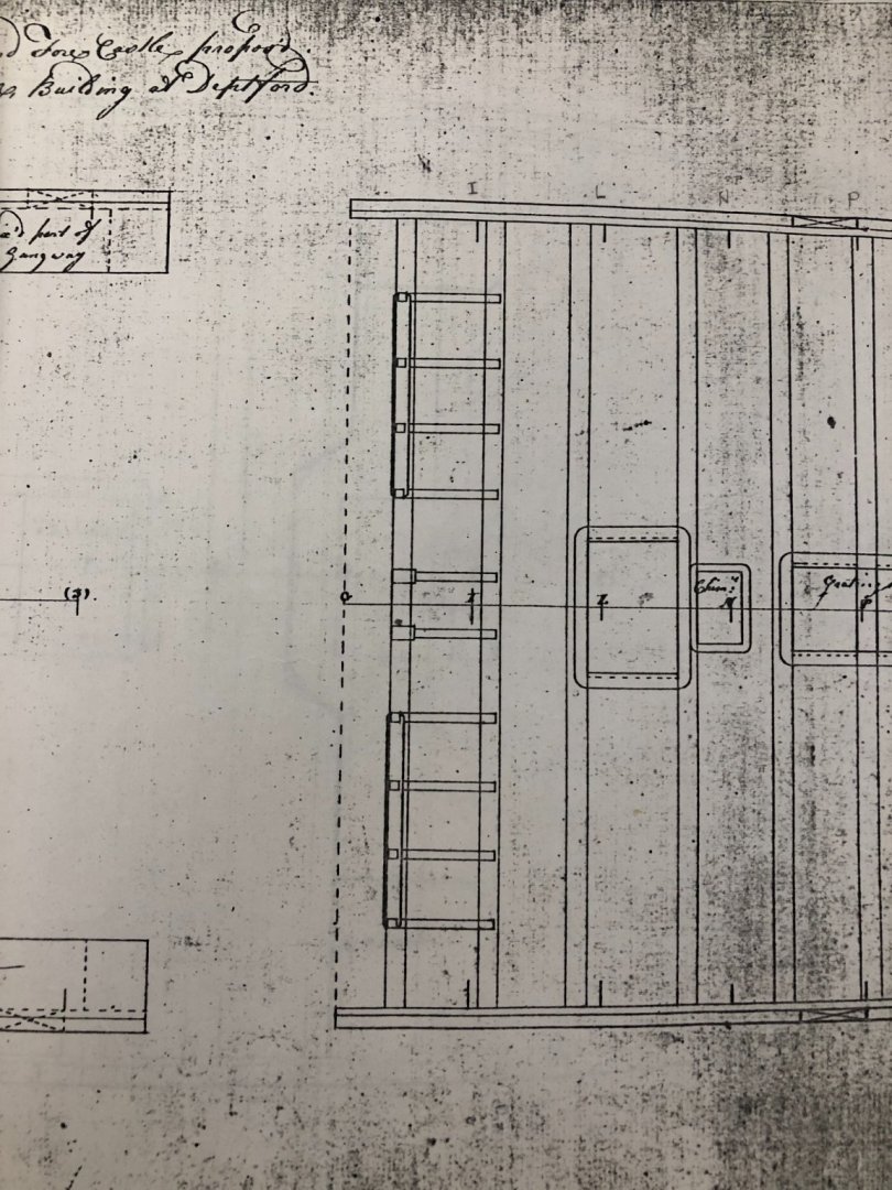
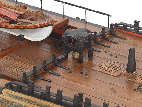
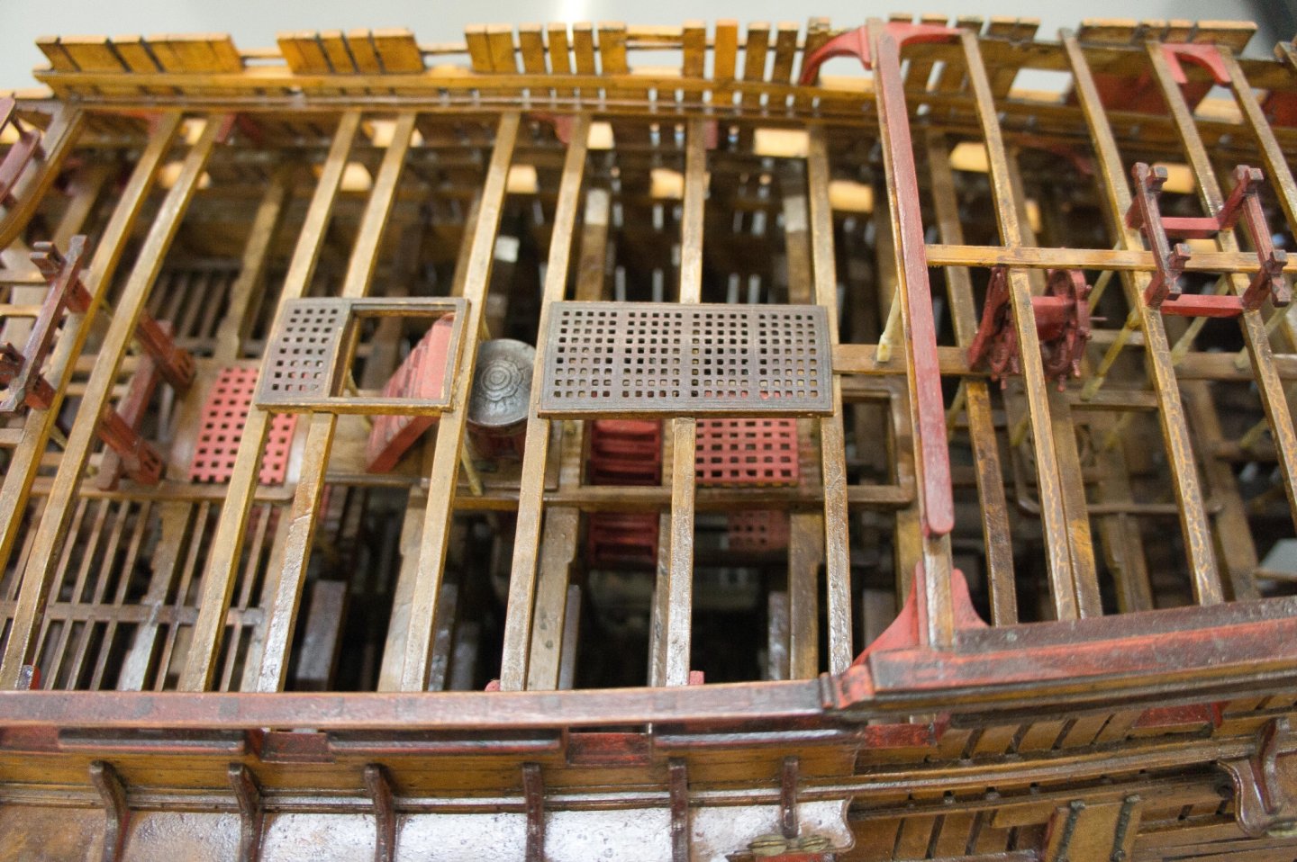
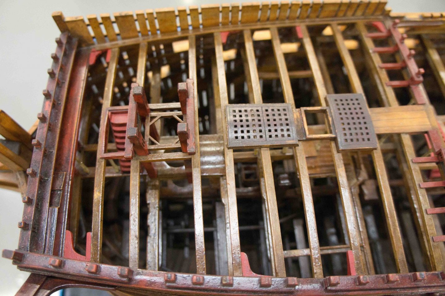
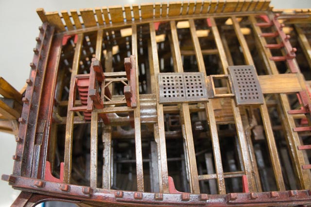
Marc, I was also struck by how the first Bellona model was so heavily aged. It looked like it had centuries of old dust crusted onto it. It must have sat out of a case for a long time, and has not been cleaned for some time. I have also noted some inconsistencies, like the gratings in some places that are grossly overscale, like they were taken from another model. Compare the upper deck and quarterdeck gratings in this image: As they say in the Western United States ranching and horse culture, this model was "rode hard and put away wet".🙂 druxey and Gary, thank you once again for your close observations and exceptionally helpful advice. I have fixed the oval hole drawing, removed the pillar under the cat beam, moved a single carling under the stove to the center, redrawn the pillars under this carling, and drawn in the large posts in the beakhead bulkhead that support the cat beam and frame the opening for the bowsprit. I think as I am getting older, my powers of observation or maybe memory are not as reliable as they used to be. For example, I got it in my head that there were two carlings under the stove, but when I went back to all of my resources, I could not find that anywhere. I made it up. It sure helps to have others more knowledgable than me checking my work! Drawing more detail has shown me a few more areas where sources show different designs, for example, the railing at the aft end of the forecastle. Thomas Slade's original drawing shows knees supporting the uprights: And we see these in the original model, although almost flush with the beams and perhaps covered in some way by the planking if it were installed? These are shown clearly above the planking in Slade's original design for HMS Victory of about the same age: But the knees are gone in the second model of the Bellona, about 20 years later: And then to make life for us poor researchers even more fun, the first Bellona model shows 2 sheaves in each upright, the second Bellona model shows 1 in each upright, and the Victory model does not appear to have any. And I don't really understand how the first Bellona model could have knees and also sheaves, because the knees would be severely cut into. And how could the rigging plan work with either no sheaves, one sheave or two? Tenons into the beam, or knees, that is the question! Best wishes, Mark

-
Hi druxey, I edited the post, replacing that PDF with a screenshot instead. Let me know if this doesn't show up either. Mark
-
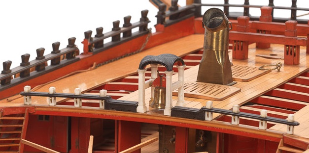
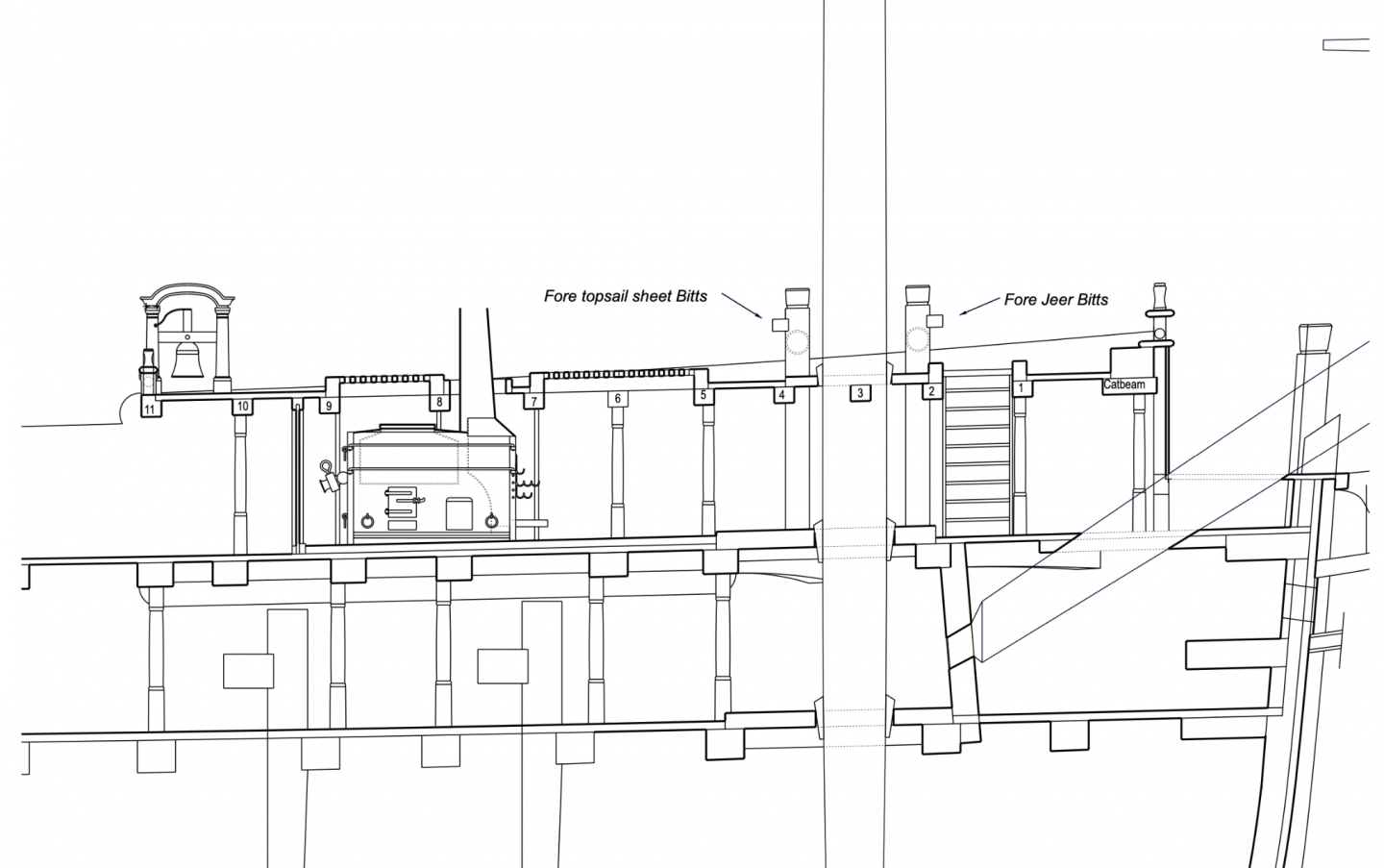
Hi everyone, I have been pretty silent for a while. I had to upgrade my CAD software because the old version would no longer run on the updated operating system. And you know what happens when software is upgraded; no end of issues to resolve. But I finally got everything working, and then kept plugging away at more details. I was mainly concerned to check alignments of things running through several decks, mostly the bitt pins but also the pillars. For details like the belfry, I looked at the second Bellona model, the HMS Victory as build ca. 1760, and the Princess Royal which I recently rediscovered was also designed by the Bellona's designer, Thomas Slade, just a year after the Bellona, as best I can tell. So I am thinking that details I can't figure out elsewhere might reasonably look like what is in the Princess Royal contemporary model. Here is a snapshot of the details I am beginning to pin down. I am also showing here a detail Gary (garyshipwright) first highlighted; how to provide a landing for planking around the bowsprit.
-
Well observed, druxey. I hadn't noticed the change in the bag of the upper rail. I wonder why, in a rebuild, they would make this change for what would be mainly an aesthetic look. Changing tastes? or they found a purpose for the space beneath the platform? In a 74 it is only about 2 feet high in the clear, and of course, split in two by the bowsprit. Mark
-
Gaetan, wardrope, very funny! And a beautiful wheel. You set the highest standard! Mark
-
Beautiful, beautiful work, Gaetan! I like seeing the shipwright assembling the tiller equipment. It really shows just how large these assemblies really are. Where does the tiller rope go after reeving through the block at the center? Is there another block that leads the rope up to the steering wheel? Mark
-
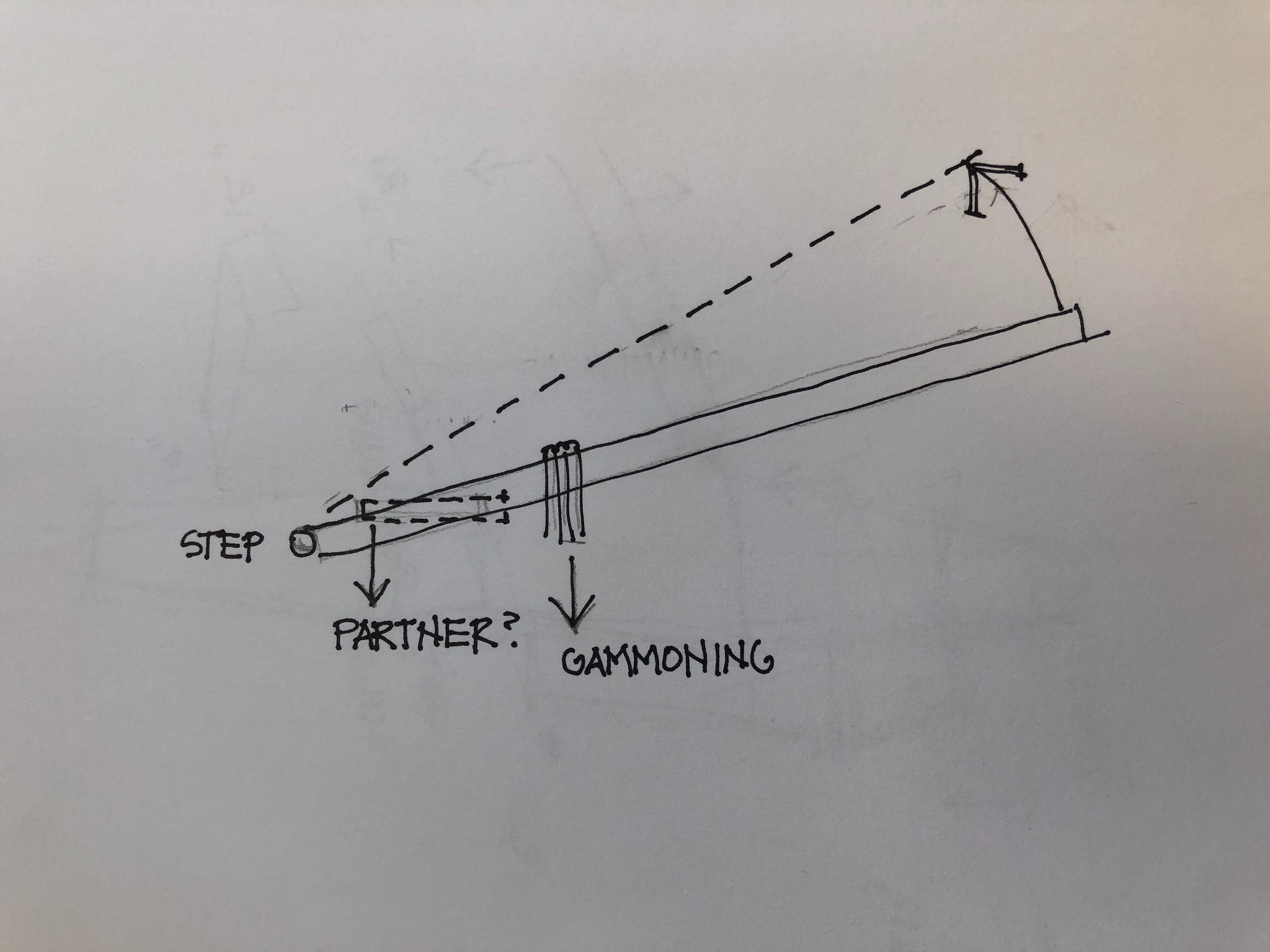
Gary One more thought. In terms of structure, the main issue to address is the upward lift of the bowsprit due to the lines mostly exerting an upward force. If we think of the bowsprit step as a pivot point, then the upward lift has to be counterbalanced by downward forces. The further away from the pivot point, the better, and the gammoning is furthest out and therefore more effective. Partners so close to the pivot point of the step would not be as effective, particularly since it would be the aft part of the partner resisting the upward lift, and this is super close to the step, less effective. In fact, if the gammoning is tight, I don't see how there would be any upward movement of the bowsprit at the location of the partners that the partners would need to resist. The engineers in the group might have a better thought about this... Mark

-
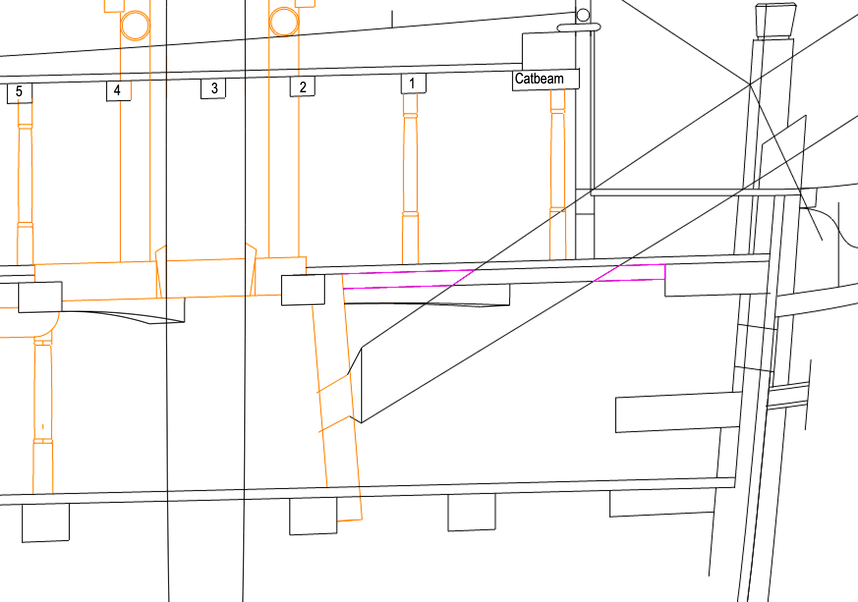
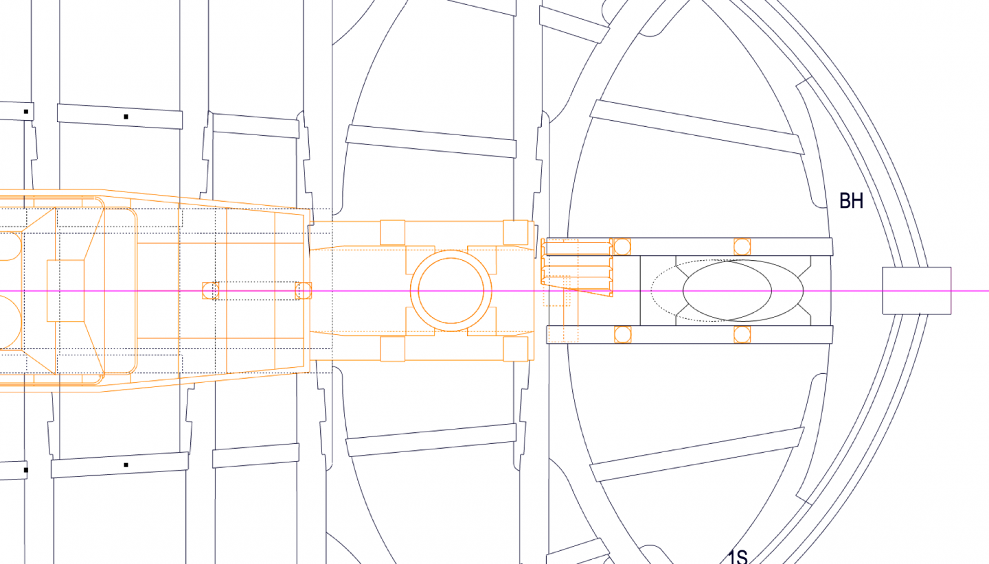
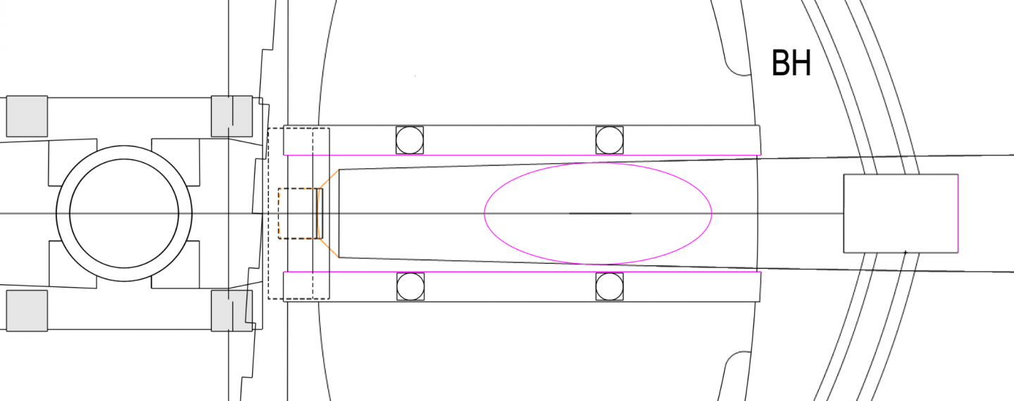
Hi Gary, Many apologies if I am late to the party in helping think about this bowsprit deck framing question. Too many things taking me away from the shop lately... But here are some more thoughts. I have always wondered about those delicate little diagonal pieces in the forecastle partners for the foremast in the first Bellona model. They can't make sense as real partners, so they must be a model-making shorthand for saying "partners go here". Although why they would detail everything else accurately and not this, I have no idea... So if that is the case, then I think druxey is right in saying that the real issue is how to land the planks around the bowsprit, coming in at an angle to the deck. I agree with Alan that this does not have to be structural, because there is already the step, the top of the stem, gammoning and stays holding the bowsprit in place. I drew in purple the areas where a "thicker than planking" but "thinner than a structural step" would be needed to land the planks around the bowsprit. There would not be a need for planking fore of the bowsprit as Siggi pointed out, particularly since it is directly beneath the platform at the beakhead; but aft is definitely a walkable area needing planking. So is this like the thicker baulking around the opening for the rudder at the stern of this deck? the purple highlighted in the cross section is the depth of the carling on either side of the bowsprit. Maybe the baulking could be a little thinner? Best wishes, Mark
-
Exceptionally eautiful work, Karl, as usual for you! I like the way you make a pattern for the hanging knees, using little pieces with a general template. I will use that idea! Mark
-
Hi Gary, I just caught up on your postings. It sure is helpful to see you working on all of the things that I know are are coming next for me! I will look around a little to see if I find anything about where the bowsprit goes through the deck.... It is looking great, including the beakhead bulkhead framing! Mark
-
Hi Alan, Great news! Now you will always have that feeling when you look at one of your details blown up in high resolution photos! Yes, I was also struck by the contrast between the precise rules for sizing blocks relative to rope diameters, only to see in Steel's tables that there is not a close correlation in many cases. They did seem to standardize on some basic block sizes, so as not to have to carry hundreds of different sized replacements. So why did they not say, "for circumferences from x to y, the sheave size is z". Who can I call about this.....😏 Mark
-
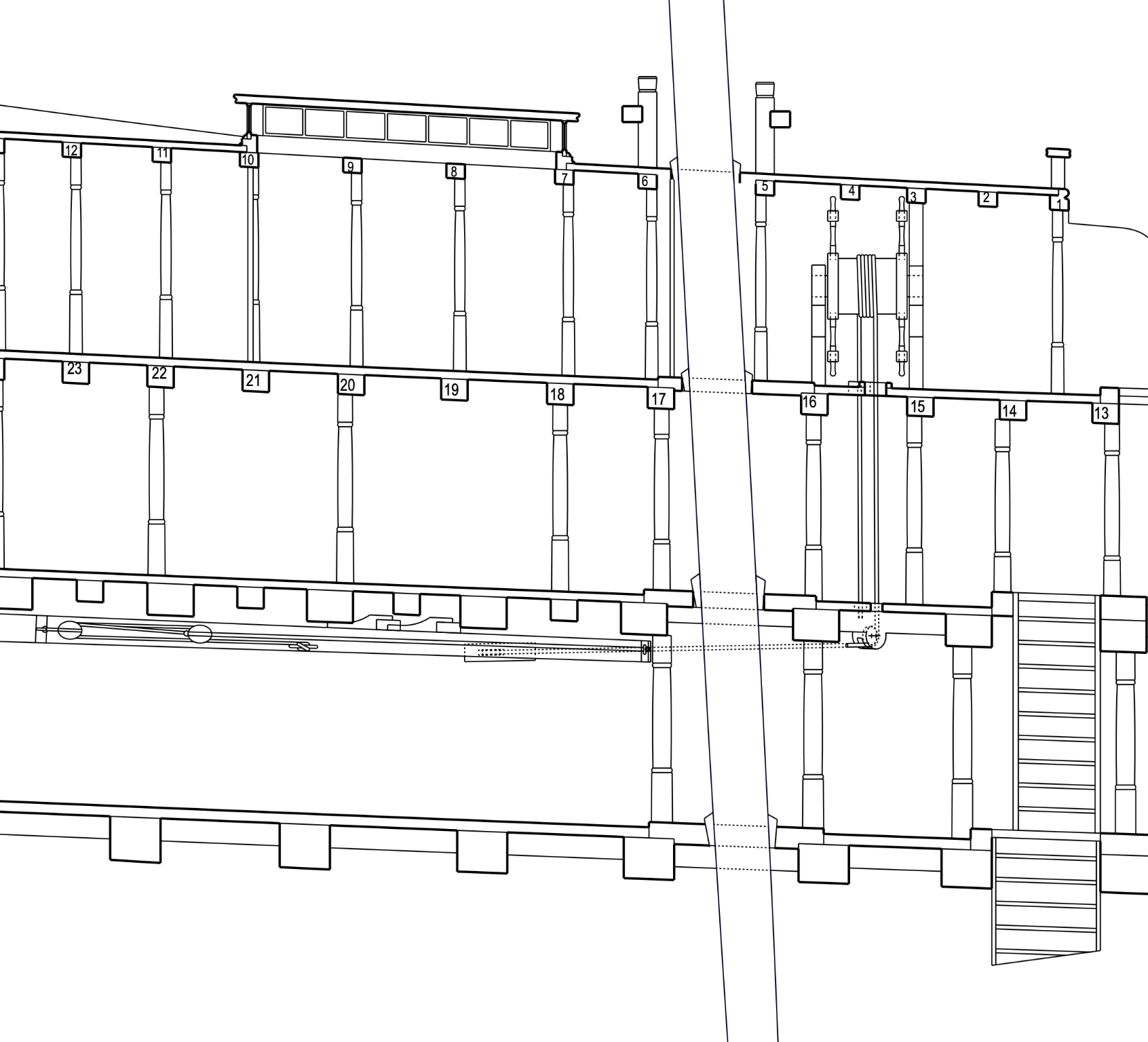
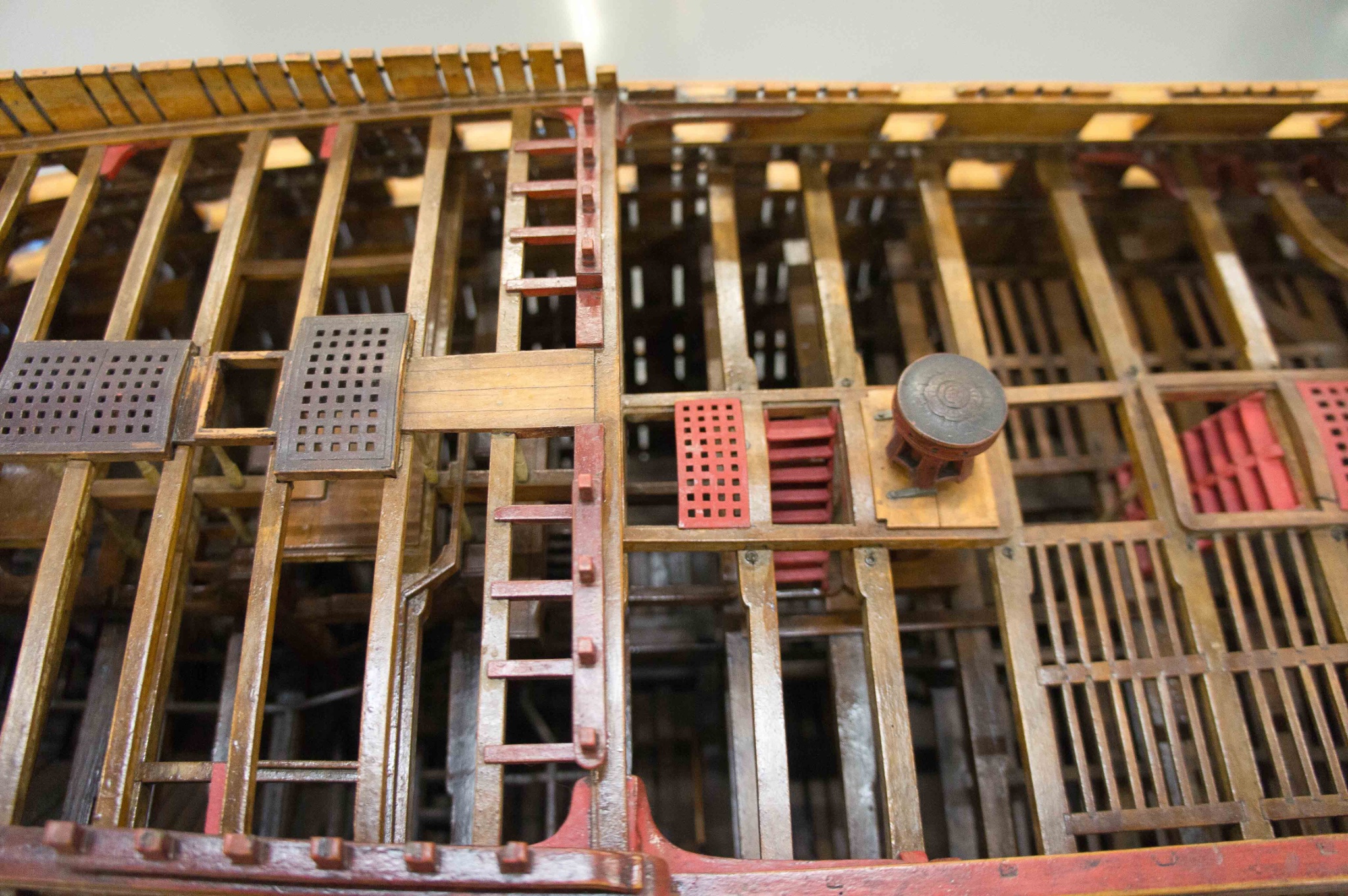
Hi druxey, I see now. I confused its length because of the wheel handle coming down in front. So it looks like it would be shorter than the actual travel of the rope lock to lock, but more than chafing in a hole just a little bigger than the rope. I will use it, because I would reasonably guess the sliding cover as in Victory would have been something later than 1760. More work on the pillars, now on the upper deck reaching to the quarterdeck and forecastle. I am mainly working from what I can see in my photos of the original Bellona model (below), and what seems rational. For example, no pillars beside the aft hatch, and therefore no pillars possible there because the centers do no line up with any beams above. No pillars close to the bitts, because they are providing vertical support at their locations. Except, the model shows pillars under the fore brace bitts on the quarterdeck. Also, iron columns beside the stove. I am not sure about pillars in the wardroom on the upper deck. It looks like there are more in the last photo below, but I can't quite see if it is every beam, and how far astern. I seem to have more beams in the quarterdeck over the wardroom than the model shows, but my beams are taken directly from the original dockyard drawings. 5:00 Mountain time, sun over the yardarm, and time for a scotch to think about it! Mark