SJSoane
-
Posts
1,655 -
Joined
-
Last visited
Content Type
Profiles
Forums
Gallery
Events
Everything posted by SJSoane
-
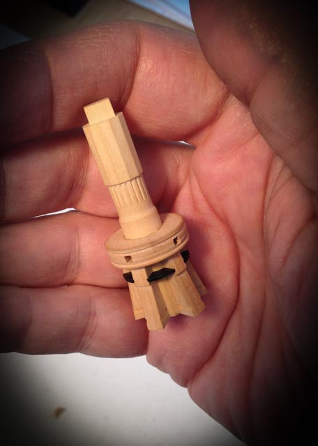
 Thanks, Grant, Mark, Michiel, Robert, Ben, druxey and Karl. This has been a steep learning curve for me. Of all the things I read over the years, and watching other great build logs on this site, I had no idea that the chocks of the capstans were going to be so challenging. They have to fit very precisely into the angles between the whelps, or you can see the mismatch; they are angled at the back to fit against the angles of the drum, which you can also see if it is not right; they are beveled on the sides to fit the birdsmouth rabbets; and they are rounded on the front so that they make a perfect circle around the capstan, which you can see if it is not a perfect circle. They are too thin to clamp in a vise without breaking them with the force of a file, and almost too small to hold in fingertips. I sanded and filed a great deal off my fingertips while working on these. I became obsessive about not letting them slip from my grasp, because there was no way I would ever find them again. I can't wait to work on a big project like the spokes of the helm! ....;-) Best wishes, Mark
 -
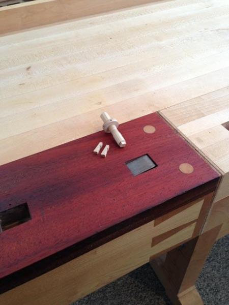
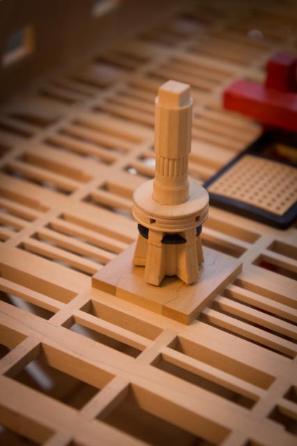
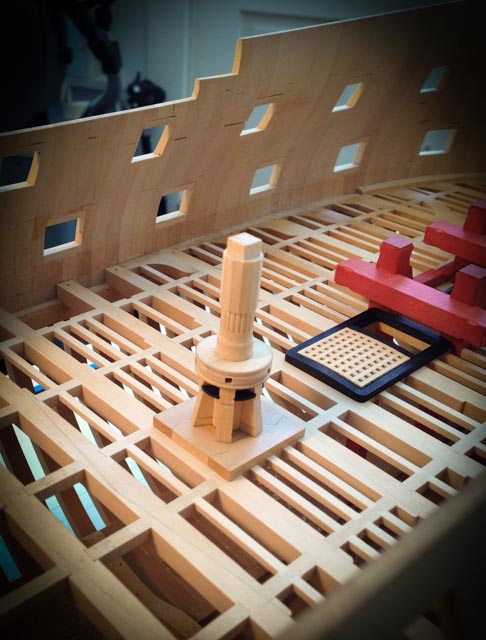
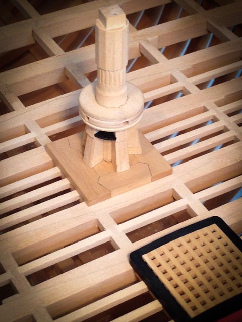
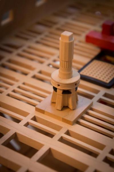
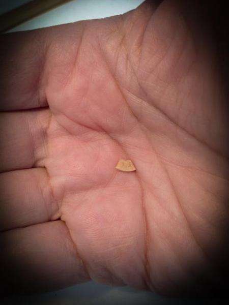
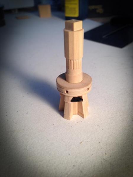
Hi everyone, The top chocks are finally finished, and I went for the black on natural idea. It is starting to look good with the natural gratings and black coamings. I have shown the size of the upper chock in my hand. Challenging. On to the lower ones... Mark


-
Hi Meredith and Ulises, I have spent the last several days creating an inventory of all of the rope I will need for the 3/16" scale Bellona 74. Then I can join you in experimenting with how to create a LH or RH rope of a given diameter, and know how big of an inventory I will need to create of each size. You keep me inspired at the possibilities of Jim's machine. Mark
-
Beautiful! It all looks obvious and straightforward when you view the headwork of a completed model. Your photos show just how exceptionally complex those pieces in the head really are. Great craftsmanship. Mark
- 662 replies
-
- 1
-

-
- bonhomme richard
- frigate
- (and 1 more)
-
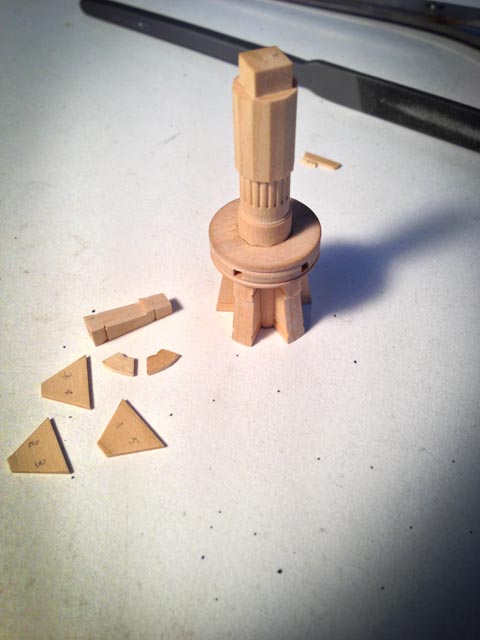
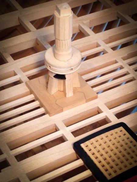
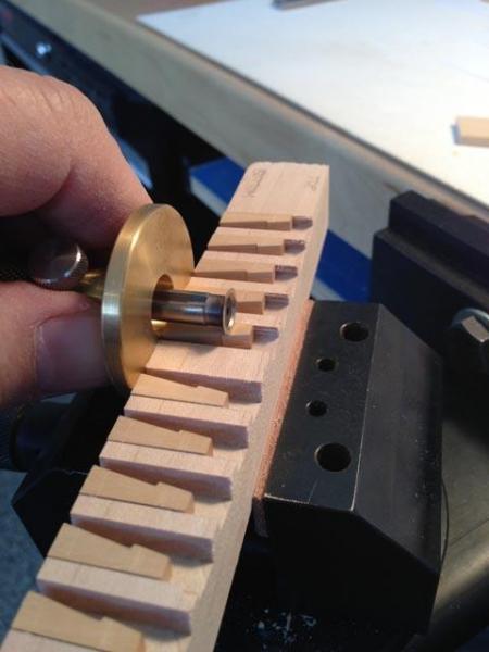
Hi Everyone, I finally got to grips with the chocks for the capstan, which I now realize had been running me into the ground. I tried a half dozen different ways to machine them since they were so small and hard to hold. But in the end, I used a table saw to cut the angles, and then chisels and files to hand fit them into their slots. Smallest pieces I have ever fabricated. I am thinking about color. I had long planned to do a red or black capstan, since so many 18th century models have one or the other. But the other day I saw the color photo of HMS Yarmouth, 1748, in Franklin's Navy Board Ship Models. It has the chocks in black, and the rest of the capstan natural. I tried one in the photo I am showing (the chock is still loose, and not yet tight up against the rabbet on top). I will sleep on it, and then decide once and for all. I have the dilemma Remco was facing about blackening his mast tops, which would hide all of his great detail. I am feeling the same about the capstan. Alex, I am glad I could help with the wood. What is IPMS? It is not too far away, if you think it is worth seeing. And flattening and refinishing my bench made it feel like a brand new tool to play with. Long overdue. I guess I can thank those pesky capstans for pushing me into any other project but a capstan.... Best wishes, Mark

-
Hi Michael, I sent you a PM. Alex, it is South American Boxwood. I bought it years ago from Woodcraft, but they have not been able to supply more for many years. I got a sample from HobbyMill that is every bit as good. You can find them at: http://www.hobbymillusa.com Mine is not as yellow as European Box; but it is a delight to work with. Fine, even grain, holds detail, cuts precisely. Best wishes, Mark
-
So after re-reading Lees and David Antscherl's book on Rigging a 6th rate sloop of war, this is how I see it for now, until someone has a better reading: Strands are twisted left handed (S direction); multiple strands are twisted right handed to form rope (Z direction); and multiple ropes are twisted left handed to form cable (S direction). Most lines are ropes twisted right hand. The largest rigging such as stays, shrouds, and anchor cables, are all cables twisted left hand. Now to make life interesting, most threads that we can buy are already twisted right hand. So to make a standard right hand rope, we need to twist enough threads left hand (Jim's counterclockwise setting) to form left handed strands, three of which are then twisted right hand to form the rope. The number of threads we load onto a supply spool will determine the size of the strands. After the strands are formed, we only load single strands onto the supply spools to form rope. And we only load single ropes to form cables. To calculate how to form a rope of a given diameter, we need to know how big the strands need to be so that three of them make up the desired rope diameter. And to make the strands of the right diameter, we need to know how many threads are needed to make the strand of the desired diameter. The same for calculating a cable. We need to know how big the ropes need to be so that three and sometimes four ropes will twist left handed to form the cable of the desired size. So, let's say a strand is .01 inches in diameter, and three are twisted together to form a rope. Has anyone spotted a standard ratio for this, where for example we could say that the three together will be 1 1/2 or 2 times the diameter of the single strands? or this this variable depending upon the material? And for those of you who then spun ropes into cables, do you see a ratio of the individual ropes sizes to the finished cable size? All for now! Mark
-
Hi Ulises, Dave and Meredith, Yes, Ulises, your comments makes perfect sense. When should we make up a line with many strands per spool, and when should we lay up a line left, then use those to lay up right, and so on? I have an old spreadsheet of all of the lines needed for the Bellona, using James Lees' book on Masting and Rigging. I will try to consolidate this into a list of the actual diameters of lines needed for the ship, with notes of whether they should be cable laid, etc. Then we can see when a certain diameter should be many strands in one rope, or left hand turned into right hand, etc. It will take me a few days; I converted from Microsoft Excel to Apple Numbers a few years ago, and a lot of cleanup is needed. But now I have partners in figuring this out! I love this website. Mark
-
Thanks, druxey, Greg, Grant, Ed and Remco. I think working on those capstans has worn me out temporarily. Each step is only an tiny move forward, and I am so ready to move on. I only need to figure out how to attach the whelps so they are evenly spaced around the drum, and get some chocks in. But it seems a long hill to climb right now.... By the way, the workbench is based on an ancient European design, shown in the Workbench Book by Scott Landis. The noted woodworker Frank Klausz shows in great detail in this book (pp. 48-61) how he built his own example of a workbench his father and grandfather used. It so inspired me 20 years ago that I built one. Only mine was left-hand, and not as well crafted as Frank's. He says something about this that I think applies to ship models as well: "It's not my design--it's a thousand years old. The only credit we can take for this is that we made it and it's nicely done." Ed, I just got the first scratches in my new finish on the bench, and initially thought, what a shame. But then I reminded myself, it is only a workbench! Remco, I haven't tried this yet, but I think a straight board used on this shooting board will not need clamping. Just pushing it against the fence, and holding it down firmly, should keep it in place. We'll see. I may have to put some lever clamps in if this doesn't work. I deliberately did not apply a finish on the jig, so that there would be friction between the board and the top of the jig. A piece of fine sandpaper attached to the top may help if it needs more friction. Mark
-
Meridith, That would be great! i only have a couple of attempts, but I'll pull the information together and post it. Best wishes, Mark
-
At some point, it would be helpful to begin recording how many threads and RH/LH steps one has to go through to create rope of a given diameter, starting with threads of different diameters. Then, when one needs a rope of a certain size, it would be easy to look up how many threads of what thickness, and how many steps are needed to construct it. Is anyone far enough along to have this kind of information? I am looking at the anchor hawsers for the Bellona 74 at 3/16" scale, for example, and wondering how many threads, ropes, etc, will be needed to get to that size. I think it will use my entire supply so far! Mark
-
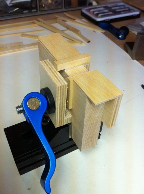
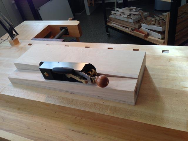
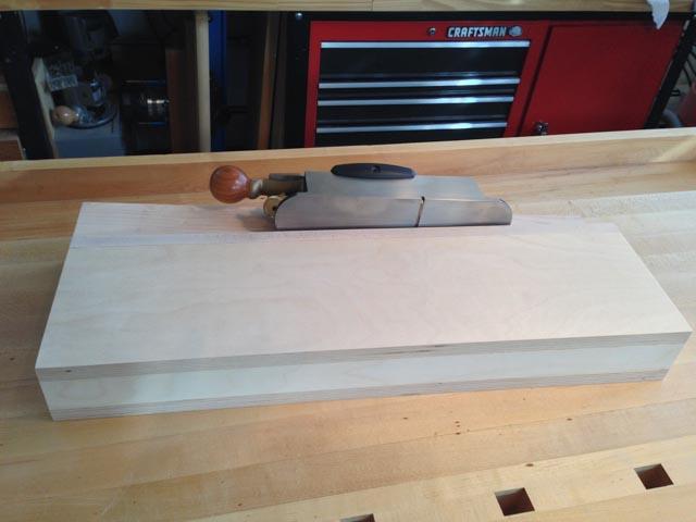
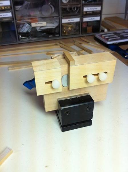
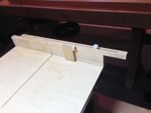
Like Remco reported the other day, I temporarily ran out of energy for the ship. I moved to a larger scale project, and finally built a shooting board for planing exact right angled and straight cuts on the edges of small boards. I found a great design online, which I modified to suit my needs. You can see the original article at: http://www.highlandwoodworking.com/woodnews/2010july/shootingboards.html This is a great design. It runs the plane along a sloping surface, so that the entire width of the plane is used to even out wear. It also provides a shearing cut, which helps with hard wood like boxwood. A shooting board works on the very clever idea that the plane blade in a normal plane does not go all the way to the side of the plane. So when it is run along the fence of the shooting board, the blade cuts into most of the fence, but not the little edge where the blades stops short of the side. This little edge provides a constant surface for guiding the plane. I still have to attach a fence, but that will have to wait for more time in the shop. With a good fence at exactly 90 degrees and a very sharp plane, I could trim the ends of slightly too long carlings, rather than using the disk sander. I'll see how it works. That is a Lie Nielsen plane designed to use with shooting boards. A gem to use. Mark
-
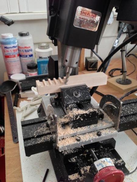
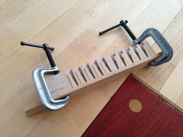
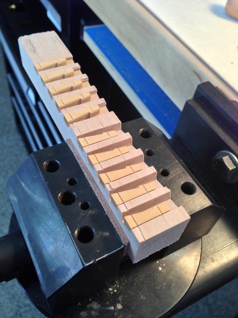
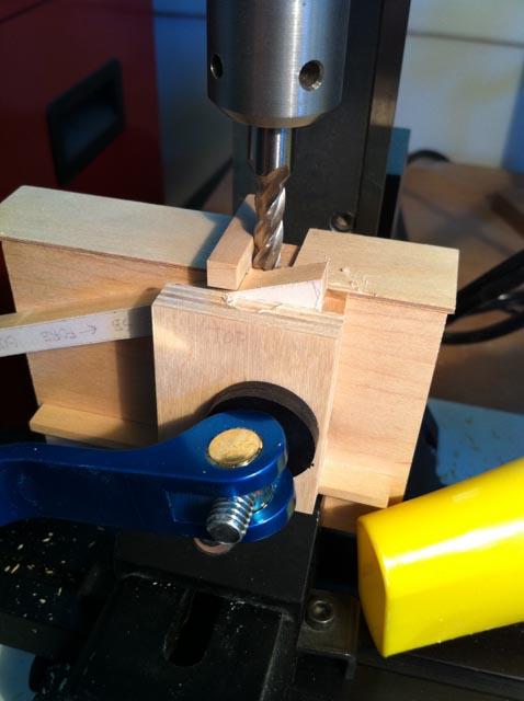
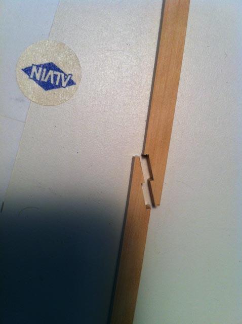
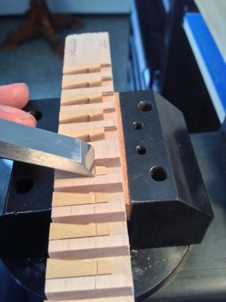
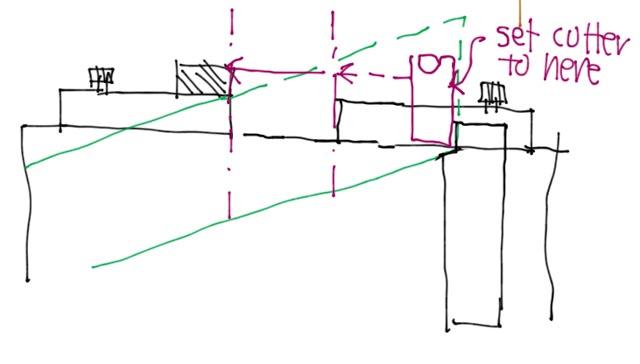
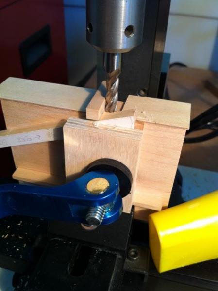
Hi everyone, I got a little further on cutting the birdsmouth rabbets on the whelps for the chocks. Using the little holding jig really helped. I was able to use the scoring marking gauge to keep the joints at the same height, and then a free-handed chisel cut for the birdmouth. By the way, I spot glued the whelps into the jig to hold them in place, then soaked them off with isopropyl alcohol 99%. The spots of glue were really tiny, but they held. Best wishes, Mark

-
Thanks, Ulises, I'll try the jig idea. It is a way better idea than stringing thread around the shop floor! Mark
-
HI everyone, I just received my Byrnes ropewalk, which is every bit as wonderful as his other tools. I have been experimenting today, learning the ropes ;-). I have a question for those of you who are a number of steps ahead of me. How do you load the supply spools with multiple threads, and keep the tension even? I tried laying out two strands of threads across the room, tied the two together at one end, and taped the tied end to the spool. Then I tried to feed the two strands onto the spool as evenly as possible. The lumpiness of the finished rope in places suggests that the tension was not even throughout. Any ideas? Best wishes, Mark
-
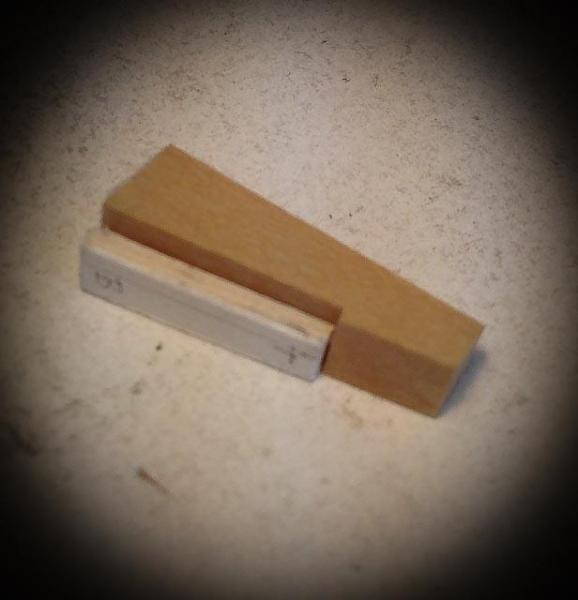
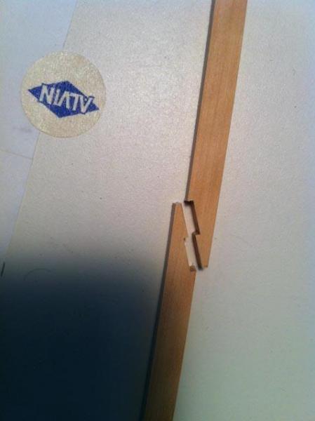
Here is a jig a built a while ago to do hooked scarphs. It allows adjustment for different lengths of scarphs. Mark

-
Gary, I had forgotten the amazing level of detail and craftsmanship in your hold. Nice to see it again! Mark
-
Byrnes table saw accessories
SJSoane replied to Neill's topic in Modeling tools and Workshop Equipment
Turn off the saw. Lower the saw blade below the insert, put in the insert and tighten the screws to firmly hold it down, turn on the saw, and raise the blade through the insert while it is running. -
Byrnes table saw accessories
SJSoane replied to Neill's topic in Modeling tools and Workshop Equipment
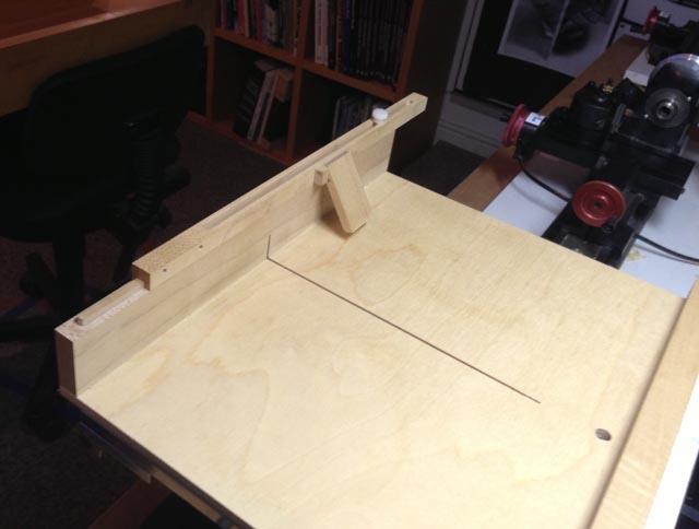
I have discovered that all of the attachments, including the tilting table, eventually are indispensable. I have also shown a few photos of a sliding crosscut table I built, with a sliding stop for repetitive cutting to length (always put a spacer between the sliding stop and the workpiece that you remove right before the cut, to avoid binding the saw). I use this constantly. Mark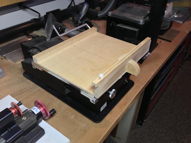
-
Hi Greg, I love to see your work. As crisp as it can get! Mark
-
Gary, This reminds me what a great build the Alfred is. It is fun to see fast-forward presentations! Mark
-
Karl, Beautiful work. It looks like a real ship in the photos. Mark
- 662 replies
-
- 1
-
-
- bonhomme richard
- frigate
- (and 1 more)
-
Hi Ed, That table of contents for Volume 2 looks terrific! Mark
-
Nice, Remco, very nice. Do you have a plan for how to mass-produce the smaller blocks? I have been thinking about that for a long time, and I look forward to your ideas! Mark
-
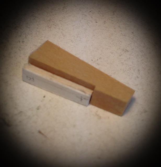
Thanks, Sinan, druxey and Remco. I built that bench many years ago when i was building furniture, which I do no more, and I had a larger shop, which I have no more. So the bench is way, way too big for the space and my needs. I walk around it every time between the Bellona and the model tools, but I can't even think about giving it up. I put my capstan on the tail vise to show the scale... I am showing a little template for marking the angled surfaces on the face of the whelps. The next challenge, which has really slowed me down, is cutting the bird mouth joints on the sides of the whelps for the chocks. They are so small that I managed to cut my own finger with the marking gauge, and I cannot see or feel the score to register the chisel for the cut. And they are angled in two directions, which means that I cannot hold them down on the bench without them squirting out from under the clamp. So I built what my wife called a little "nest" for the whelps, with a two direction angled rabbet in a piece of maple for each one. It keeps them all level in both directions. When I get my energy back, I should be able to score them all at once with a straight edge across the group. And the last photo shows the latest carlings, and the two parts of the main hatch awaiting its coamings and round-up. Never as much progress in a weekend as I always hope for..... Mark